1. Introduction
The trisection of an acute angle (except that of 45˚) has been one of the most intriguing geometric challenges for mathematicians for centuries going back to 250 B.C., during which time it has been classified as one of the three unsolvable problems of Geometry—the other two being the squaring of a circle and the doubling of a cube [1] [2] .
Simply stated and also “proven”, first by Pierre Wanzel in 1837: the trisection of an arbitrary acute angle (except 45°) cannot be achieved using an unmarked straightedge and compass only [3] [4] , or, as stated by Underwood Dudley, author of A Budget of Trisections, “There is no procedure, using only an unmarked straightedge and a compass to construct one-third of an arbitrary angle” [5] . Also, in the same text, Dudley then proceeded to lay out a proof of this statement by showing that a 60° angle cannot be trisected [5] . Yet, there have been countless unsuccessful attempts, until now, by a number of mathematicians to either disprove this assertion or devise a construction that is as close as possible to the exact solution.
The object of this paper is to present a graphical procedure, capable of dividing an arbitrary acute angle into three exactly equal parts, using only an unmarked straightedge and compass.
This procedure, which is an alternate, Method 2, to that presented in earlier articles entitled, “A Procedure for Trisecting an Acute Angle” [6] and “A Key to Solving the Angle Trisection Problem”. [7] is also based on earlier article entitled, “Mechanism Analysis of a Trisector” [8] .
Thus, the approach being presented required (a) designing a working model of a trisector mechanism (see Figure A1), (b) studying the key elements of the mechanism, and (c) applying the fundamental principles of principles of Kinematics [9] , instead of conventional mathematics and plane geometry to solve the trisection problem.
The basis for employing this approach, was the fact that while it was thought that the angle trisection could not be achieved using an unmarked straightedge and compass, yet a mechanism can be built to perform the task perfectly [10] .
Hence, performing a motion analysis on an actual trisector seemed a logical rationale for seeking to obtain a fresh insight into understanding the trisection problem.
To be clear, Kinematics [9] is the study of motion, and the purpose of the trisector model was simply to study and gain an understanding of its motion. Therefore, it is not a violation of the unmarked straightedge and compass rule. For further details on the motion analysis, see reference [9] .
2. Theory
The design and operation of the trisector is based on the well known Archimedes’ construction [2] represented in the diagram below, that illustrates the geometric requirements that must be met in order to arrive at an exact trisection, and the general theorem relating arcs and angles.
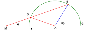
Let ÐECG (or 3ÐӨ) be the required angle to be trisected. With center at C and radius CE describe a semicircle. Given that a line from point E can be drawn to cut the semicircle at S and intersect the extended side GC at some point M such that the distance SM is equal to the radius SC, then from the general theorem relating to arcs and angles,
ÐEMG = 1/2 (ÐECG – ÐSCM) (1)
2ÐEMG + ÐSCM = ÐECG (2)
Since ΔCSM is an isosceles Δ
ÐSCM = ÐEMG = ÐӨ (3)
Therefore 3ÐEMG = ÐECG or 3ÐӨ = ÐECG or ÐEMA = 1/3ÐECG (4)
To Summarize:
Once, segments SM, SC, E’C, and CG are all equal, and ÐSMA = ÐSCA.
Then, EXACT trisection of given angle ÐECG is achieved or ÐEMA = 1/3 ÐECG.
Note also that, except for the given angle (ECG), being an acute angle, there are no other restrictions on the measure of this angle.
Therefore, the measure of ÐECG can be any real number (or arbitrary).
3. Trisector Design and Analysis
The trisector mechanism [6] [7] [8] [9] illustrated in Figure 1(a) is modeled after the Archimedes’ Construction [2] discussed above. This is a compound mechanism [9] consisting of a slider-crank linkage CVF [9] and a sliding-coupler linkage CVE [9] , where both linkages share a common crank CV and a common connecting rod E’F. Also link section VF and cranks CV and CE are all equal in length.
Mechanism operating as a slider-crank [6] [7] [8] [9] (Figure 1(b)):
In this operating mode, as crank CV is rotated in one direction or the other, between the 180˚, and 90˚, positions, the connecting rod E’F undergoes combined motion, where sliding occurs only at the end F, as the rod is constrained to move within the fixed horizontal slot, while both sliding and rotation occur at the other end E’, where the rod moves within the pivoting slot. Meanwhile, the angle that the connection rod E’F makes with the horizontal slot maintains a constant relationship that is 1/3 of the angle formed by link CE and said slot. Or, ÐE’FC = 1/3ÐE’CG.
Mechanism operating as a sliding-coupler [6] [7] [8] [9] (Figures 1(c), and 1(d)).
For this operating mode, we assume link CE’ is held at a fixed angular position (i.e. the angle to be trisected) and the connecting rod E’F is disconnected from the horizontal slider and renamed E’F’. Therefore, as crank CV is rotated in one direction or the other, the mechanism then behaves like a sliding-coupler, where E’F’, acting like a coupler, undergoes sliding and rotation at the pivoting slot end E’ and pure rotation at the free end F’, since F’ is not constrained as before to move within the horizontal slot. In this mode, it can be seen that the path of F’ (see Figure 1(c)) is actually a smooth circular path that intercepts the horizontal path that it would normally describe when constrained within the horizontal slot. This point of interception is a unique point, as it locates the vertex of the required trisection angle (ÐE’MG or ÐE’MA = 1/3ÐE’CG), formed by the connecting rod E’M and the horizontal slot to comply with the Archimedes’ Construction [2] . See Figure 1(d) and note the identical angular relationship between this figure and Archimedes’ Construction [2] shown in Section 2 on THEORY.
4. Procedure
To illustrate the procedure, we will consider the 30˚ and 60˚ angles, both of which represent a typical acute angle that has been “proven” to be not trisectable, and the 45˚ angle which is known to be trisectable, for benchmarking. Then, let it be required to develop a construction for dividing each of these angles into three exactly parts, using an unmarked straightedge and compass only.
The construction layouts for the 30˚, 45˚, and 60˚ cases are given in Figures 2-4.
STEPS
1. Using CG as the base, erect a perpendicular CC’ at C.
2. With center at C and radius CE’, describe an arc to cut CC’ at a point E.
3. Using CE as the base, form an equilateral triangle CEV, where V is the vertex.
4. Extend segment EV to meet GC (extended) at a point F.
5. Join F to E’ with segment FE’.
6. With CV as the radius and C the center, describe an arc from V to cut FE’ at a point V’ and FG at a point A.
7. With FV as the radius and center at F, describe an arc from V to cut segment FE’ at W.
8. Extend segment E’F to a point F’ by a distance equal to segment V’W.
9. Join V to A with segment VA.
10. At F’, erect a perpendicular ray, F’Y, to base line FG.
11. From F’, draw a ray F’X parallel to segment AV.
12. Bisect the angle ÐXF’Y with bisector F’Z cutting baseline FG at a point P.
13. Join E’ to P, cutting arc AV at a point R.
14. Join R to C with segment RC.
15. With center at R and radius equal to RC, locate a point N in segment PE’.
16. Join N to F’ with a segment NF’.
17. Bisect NF’ with the bisector meeting line E’C (extended) at a point O.
18. With center at O and radius OF’, describe an arc to cut the baseline FG at a point M.
19. Join E’ to M with segment E’M, cutting AV at a point S, to form the required trisection angle ÐE’MA.
20. Join S to C with a segment SC to complete the construction, which makes segment SM equal to segment SC.
21. Measure angle ÐE’MA. This angle, (measured to the nearest hundred thousandths, with the aid of The Geometer’s Sketch Pad) [11] , yields for the 30˚ case, 10.00000˚: for the 45˚ case, 15.00000˚: and for the 60˚ case, 20.00000˚.
Note that Steps 15 to 21 of this procedure are best described with the aid of the schematic in Figure A2, where the relationships among points P, N, M, and F’ are more clearly shown.
NOTE
It should be noted that The Geometer’s Sketchpad [11] software was employed not only for its precision and accuracy in terms of measurements, but mainly for its strict adherence to the unmarked straightedge and compass rule, where the constructions are built with strict adherence to the unmarked straightedge and compass rule.
Also note that the only role the trisector mechanism played in the development of the procedure was to enable one to observe its operation and, based on its unique motion, perform the appropriate kinematic/displacement analysis that produced the results obtained.
![]() (a)
(a)![]() (b)
(b)
Figure 2. (a) Composite Construction Showing Trisection of 30˚ Angle Yielding ÐE’MA = 10.00000˚; (b) Resultant Angles for 30 × 10 Trisection.
![]() (a)
(a)![]() (b)
(b)
Figure 3. (a) Composite Construction Showing Trisection of 45˚ Angle Yielding E’MA = 15.00000˚; (b) Resultant Angles for 45 × 15 Trisection.
![]() (a)
(a)![]() (b)
(b)
Figure 4. (a) Composite Construction Showing Trisection of 60˚ Angle Yielding ÐE’MA = 20.00000˚; (b) Resultant Angles for 60 × 20 Trisection.
5. Proof
Referring to Figures 2(b), 3(b), and 4(b) above, and applying the general theorem relating to arcs and angles (see Section 2 on THEORY of this paper), we get
ÐE’MG = ½(ÐE’CG – ÐSCM) or ÐE’MA = ½(ÐE’CG – ÐSCM)
2ÐE’MA = ÐE’CG – ÐSCM
2ÐE’MA + ÐSCM = ÐE’CG
Since
ÐSCM = ÐE’MA
Then
3ÐE’MA = ÐE’CG
Therefore,
for the 30˚ trisection ÐE’MA = 1/3ÐE’CG = 1/3(30°) = 10.00000˚ (QED)
for the 60˚ trisection ÐE’MA = 1/3ÐE’CG = 1/3(45°) = 15.00000˚ (QED)
for the 60˚ trisection ÐE’MA = 1/3ÐE’CG = 1/3(60°) = 20.00000˚ (QED)
To summarize:
for ÐE’CG = ɵ … ÐE’MA = 1/3Ðɵ
Note that these numerical results obtained by The Geometer’s Sketch Pad [11] .
Represent the highest level of accuracy and precision (e.g. five decimal places) attainable by this software.
6. Summary
A comprehensive graphical procedure for trisecting an arbitrary acute angle, using an unmarked straightedge and compass only, has been presented.as an alternate (Method 2) to earlier published article entitled, “A Procedure For Trisecting An As Acute Angle” [6] .
The procedure, when applied to the 30˚ and 60˚ angles that have been ‘proven’ to be not trisectable as well as the 45˚ benchmark angle that is known to be trisectable, each produced a construction having an identical angular relationship with Archimedes’ Construction [2] as in Section 2 on THEORY of this paper, where the required trisection angle has been found to be one-third of their respective angles That is;
ÐE’MA =1/3 ÐE’CG) … Or, for ÐE’CG = ɵ Then ÐE’MA = 1/3Ðɵ
For example, the trisection angle for the 30˚, 45˚ and 60˚ angles were 10.00000˚, 15.00000˚, and 20.00000˚, respectively, as shown in Figures 2(b), 3(b) and 4(b) and Section 5 on PROOF in this paper. Therefore, based on said identical angular relationship and the numerical results (i.e. to five decimal places), which represent the highest degree of accuracy and precision attainable by The Geometer’s Sketch Pad software, [11] , one can only conclude that the geometric requirements for arriving at an exact trisection for both the 30˚ and 60˚ angles (that have been “proven” to be not-trisectable) and the benchmark 45˚ angle (that is known to be trisectable) have been met.
Furthermore, the construction, by demonstrating its capability of trisecting both the known trisectable angle (i.e. 45˚ angle) and lhe “proven” non-trisectable angles (i.e. 30˚ and 60˚ angles), it also demonstrated its validity for trisecting any arbitrary acute angle. Therefore, one can only conclude that the long sought solution to the age-old Angle Trisection Problem has been finally accomplished, despite the theoretical proofs to the contrary by Wantzel, Dudley, and others [3] [4] [12] [13] [14] [15] [16] .
Note that, as stated in the reference articles [6] [7] [8] , the use of a trisector model [A1], was only to study and gain an understanding of the motion of key elements. Therefore, it is not a violation of the unmarked straightedge and compass rule.
Appendix
![]()
Figure A2. Schematic Showing Relationships of M, P, N, and F’.