The Influence of the Model Fractal Parameters on the Electromagnetic Response in Environment with Cylindrical Layers ()
1. Introduction
The induced polarization effect has an electrochemical origin and is usually associated with geological and biological environments [1] [2] [3] . As a consequence of this effect, electrical resistivity values in these environments are complex and frequency-dependent.
In geophysics, the induced polarization method uses fact that the constituent parameters of rocks (conductivity and permittivity) are frequency-dependent to carry out prospecting activities. This method was originally applied to the prospecting of disseminated ores, and has gradually evolved over the years, currently being used in mineral discrimination [4] and environmental studies [5] and [6] .
The quantitative interpretation of field induced polarization data is a difficult task due to the fractal nature of geological environments and the inductive coupling caused by electromagnetic interactions between the environment and the electrode arrays used for current injection and potential measurements. The interpretation of these kinds of data requires a physical model to explain the behavior of a polarizable environment in an ample frequency range.
Several relaxation models have been proposed to describe the electrical polarization of rocks, in the works of Debye [7] , Cole-Cole [8] , Davidson and Cole [9] and Dias [10] , each taking into account a certain specific characteristic for a given frequency range, limited to 102 Hz. Relaxation models demonstrate the general behavior of the amplitude spectrum and the complex resistivity phase (conductivity) at different frequencies for different types of materials. The most widely used model is the Cole-Cole model, which does not, however, consider the fractal nature of the environment.
Rocha [11] developed a model that considers the fractal effects of porous surfaces and includes rock volume response, namely the fractal model for complex resistivity. This model accounts for the electrical properties of rocks at a higher frequency range than traditional models. The introduction of the roughness factor in this model allows for the investigation of rock texture, which is very important when attempting to describe the electrical behavior of rocks. This means that parameters representing the fractal geometry of the environment exist, which may be, in turn, related to rock texture. With this, it is possible to obtain important and accurate geological information of the subsurface from electrical data obtained on the terrain surface.
Rocha [11] and Rocha & Habshy [3] determined the response of a terrain presenting three horizontal layers, with the second layer polarizable with its intrinsic properties given by the fractal model for complex resistivity of [11] and analyzed the induced polarization response. These authors observed that the parameters related to the fractal geometry of the model dominate the phase response of the apparent complex resistivity at low frequencies, and also found that the fractal exponent does not depend on the electrical properties of the fluid filling the rock cavities.
The fact that the fractal exponent is independent from the electrical resistivity of the percolating solutions avoids any influence of the invasion zone in the electric profiling of wells. Thus, it is interesting to investigate the response of a polarizable medium in well environments by applying the fractal model for complex resistivity.
Farias et al. [12] [13] simulated the fractal model for complex resistivity as being an intrinsic electrical property of horizontal environments with superficial and volumetric formations (2-D and 3-D geological models), with applications for both contaminated and non-contaminated environments. The results demonstrated that anomalies are well-detected and observable by images of the parameter distribution of the fractal model, being an alternative in the detection of anomalies in the geologic environment, such as in the study of environmental contamination. The fractal complex resistivity model, however, has not yet been applied as an intrinsic electrical property in the analysis of the polarization response of cylindrical environments.
The main aim of electrical well profiling is to estimate the electrical resistivity of the geological formation where the well is inserted. However, the response of the resistivity profiling is influenced by the resistivity of the formation itself, as well as by the invaded zone, which is generated during the drilling process. Therefore, the effects of this invaded area should be avoided.
In the present study, the fractal model for complex resistivity [11] is employed as an intrinsic electrical property of an environment with cylindrical layers (the well, invaded zone and formation) to evaluate the influence of the parameters of the fractal model in the induced polarization response in this geological geometry. The model parameters represent the fractal geometry of the environment which, as presented previously, can be related to the texture of the rocks in the analyzed environment.
2. The Fractal Model
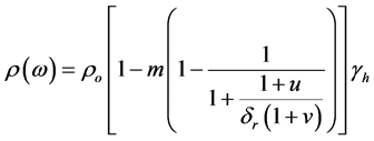
Representing the time dependence of the electric field as e−iωt, the expression proposed by [4] for the complex resistivity  is:
is:
 (1)
(1)
where  is the DC resistivity of the material; m is the chargeability defined by [14] ; δr is the parameter that relates the resistivity of the conductive grains blocking the pores of the geologic environment to the DC resistivity of the rock matrix;
 ;
; ;
; ; τ is the relaxation time constant related to the double-layer oscillations; τo is the relaxation time constant associated with the material as a whole; τf is the time of fractal relaxation, related to the time involved in the charge and energy transfer in the rough interfaces; and η is the parameter directly related to the fractal geometry of the environment, determined by the type and distribution of the mineral that causes the polarization at low frequencies.
Some typical values of the fractal model parameters for complex resistivity cited by [11] , are: ;
; ;
; ;
; ;
; ;
;  and
and .
.
3. Induced Polarization Response in a Stratified Cylindrical Environment
Normally a four-electrode configuration is used to measure the complex resistivity of a geological environment. An electric current is introduced into the environment via an electrode pair (A and B) and the voltage is measured by the other electrode pair (M and N). Figure 1 illustrates the four-electrode configuration used in the present study to determine the apparent resistivity on an environment presenting cylindrical layers.
![]()
Figure 1. Illustration of the four-electrode configuration applied to a stratified cylindrical environment.
To calculate the potential measured by the receiver electrode pair, the electromagnetic problem for a four-electrode configuration must be solved. From Maxwell equations and assuming a time dependence of the  type, we have:
 (2)
(2)
 (3)
(3)
where  is the current density due to the source; ε is the effective dielectric constant and μ is the permeability of the environment and is approximated by the permeability of vacuum. Combining the conductivity
 ![]() and displacement factor
and displacement factor![]() , the current density can be denoted as:
, the current density can be denoted as:
![]() (4)
(4)
and (3) can be denoted as:
![]() (5)
(5)
When applying the divergence operator to (2) and (5), the following equations are obtained:
![]() (6)
(6)
![]() (7)
(7)
where the left side of (7) is a result of the charge accumulation caused by the injected current. When observing (6), the Maxwell equations can be displayed in terms of a vector potential A and scalar potential ![]()
![]() (8)
(8)
![]() (9)
(9)
observing (4), (5), (8) and (9), and considering the condition
![]() (10)
(10)
where ![]() is the complex conductivity. Thus, the wave equations below are obtained:
is the complex conductivity. Thus, the wave equations below are obtained:
![]() (11)
(11)
![]() (12)
(12)
with![]() . Specifying the current density in cylindrical coordinates, with
. Specifying the current density in cylindrical coordinates, with
![]() (13)
(13)
where u is a Heaviside function, I is the current intensity, z1 and z2 are the positions of the current electrodes (A e B) and ez is the unit vector in the z direction.
Considering (8), (9) and (10) and the fact that the vector potential is of the (0,0,Az) form, the following equations are obtained:
![]() (14)
(14)
![]() (15)
(15)
With ![]() being the solution for (11) in the internal region of the well, then
being the solution for (11) in the internal region of the well, then
![]() (16)
(16)
is valid for![]() , where a is the well radius. If
, where a is the well radius. If ![]() is the solution to (11) in the invaded zone, then
is the solution to (11) in the invaded zone, then
![]() (17)
(17)
is valid for![]() , where b is the radius of the invaded zone. In the same manner, regarding the formation, with a solution
, where b is the radius of the invaded zone. In the same manner, regarding the formation, with a solution![]() , the following equation is obtained:
, the following equation is obtained:
![]() (18)
(18)
for![]() . The tangential components of
. The tangential components of ![]() and
and ![]() are continuous in the interfaces, or
are continuous in the interfaces, or
![]()
and
![]()
thus, by using (14) and (15) the boundary conditions to solve (16), (17) and (18) are obtained.
![]() (19)
(19)
![]() (20)
(20)
![]() (21)
(21)
![]() (22)
(22)
In order to solve Equations (16), (17) and (18) subject to the boundary Equations (19), (20), (21) and (22), it is convenient to introduce the Green ![]() equation, that satisfies the following equations:
equation, that satisfies the following equations:
![]() (23)
(23)
![]() (24)
(24)
![]() (25)
(25)
subject to the boundary conditions below:
![]() (26)
(26)
![]() (27)
(27)
![]() (28)
(28)
![]() (29)
(29)
The solutions to Equations (23), (24) and (25) are given by:
![]() (30)
(30)
Since ![]() is regular in
is regular in![]() , then
, then![]() , thus:
, thus:
![]() (31)
(31)
Using the identity (15) [15] :
![]()
in Equation (31), the following equation is obtained:
![]() (32)
(32)
valid for![]() ;
;
![]() (33)
(33)
valid for![]() ; and
; and
![]() (34)
(34)
in![]() , where
, where ![]() and
and ![]() are modified Bessel functions of order zero of the first and second species, respectively, and
are modified Bessel functions of order zero of the first and second species, respectively, and ![]() and R are given by:
and R are given by:
![]() .
.
The vector potential function ![]() is determined by the integral of the Green function
is determined by the integral of the Green function![]() :
:
![]() (35)
(35)
Imposing boundary conditions (26)-(29) in Equations (32), (33) and (34), functions B, C, D and E are determined. In this way, the following system of equation is obtained:
![]()
to calculate the induced potential difference measured by electrodes M and N (Figure 1). Thus only the vector potential ![]() must be obtained, which is associated with the function
must be obtained, which is associated with the function![]() . Solving the above system, the following equations are obtained:
. Solving the above system, the following equations are obtained:
![]() (36)
(36)
![]()
When combining Equations (32) and (35), ![]() can be written as:
can be written as:
![]() (37)
(37)
With ![]() given by Equation (36). The potential difference measured by electrodes M and N is given by the line integral:
given by Equation (36). The potential difference measured by electrodes M and N is given by the line integral:
![]()
with![]() , so
, so
![]()
thus,
![]() (38)
(38)
The potential ![]() is calculated as follows:
is calculated as follows:
![]()
where ![]() is the radial position of the electrodes in the well and
is the radial position of the electrodes in the well and ![]() and
and ![]() are the vertical positions of the potential electrodes. The integral of Equation (38) is solved by quadrature technique [16] or by digital filters [17] .
are the vertical positions of the potential electrodes. The integral of Equation (38) is solved by quadrature technique [16] or by digital filters [17] .
A similar result was found by [18] in the study of the anisotropy effect on resistivity measurements in wells and by [19] in the study of a dynamic model for resistivity and induced polarization data in wells.
4. Results
The induced polarization responses of the two geological two situations were obtained by applying Equation (38): 1) the environment presenting two cylindrical layers (the well and the formation); 2) the environment presenting three cylindrical layers (the well, the invaded zone and the formation). The resistivity of the mud for the two geometries was of 1 Ω・m when disregarding the polarization effect. The distances between the electrodes, in meters, were of 0.41, 6.1, 20.9 and 26.59 for AM, NA, BN and BM, respectively. The default value for the well radius was of 10 cm .
In order to analyze the influence of parameters η, m, δr, τ and τf of the fractal model, the simulations were carried out for three different values for each of these parameters, and when variations in a certain parameter occurred the others assumed the typical values described above.
4.1. Environment Presenting Two Layers
Figure 2 displays the induced polarization response for a well with only two cylindrical layers (mud and formation). The following values were used: 0.25, 0.5 and 0.75 for the fractal exponent η; 0.25, 0.5 and 0.75 for chargeability; 0.1, 1 and 10 for parameter δr; 10−9 s, 10−6 s and 10−3 s 3 for the time constant τ and 10−4 s, 10−3 s and 10−2 for the fractal time constant τf.
It is observed from Figure 2 that the fractal model for complex resistivity can be used in a wide frequency range at environment with cylindrical layers. As in the case of horizontal layers [11] , the fractal parameters η, δr e τf, particularly the fractal exponent η dominates the phase angle response of the apparent complex resistivity, mainly at low frequency. According to [2] [11] , this feature is very important because at low frequency the parameters carry information about the roughness of the pores of rocks. Thus, it becomes possible to investigate, from
data of induced polarization in the frequency domain in the well, the transport properties of the geological environment.
4.2. Environment Presenting Three Layers
Three thicknesses of the invaded zone were considered when analyzing the induced polarization response in an environment with three cylindrical layers (mud, invaded zone and formation): one, two and five times the radius of the well. The DC resistivity of the invaded area was presumed equal to 10 Ω・m. Figures 3-7 shows the response of the induced polarization when varying η, m, δr, τ and τf, respectively:
The amplitude response of the apparent complex resistivity was affected by the variation of the invaded zone. However, the phase angle response was only slightly affected. This is similar to the results observed by [2] [3] , which demon-
![]()
![]() (a) (b)
(a) (b)![]() (c)
(c)
Figure 3. Amplitude and phase angle of the complex apparent resistivity in a well presenting mud, an invaded zone and formation. The invaded zone and formation are polarizable, and the intrinsic electrical properties are given by the fractal model when varying the parameter η. The radii of the invaded zone were (a) the same; (b) twice and (c) five times the well radius.
![]()
![]() (a) (b)
(a) (b)![]() (c)
(c)
Figure 4. Amplitude and phase angle of the complex apparent resistivity in a well presenting mud, an invaded zone and formation. The invaded zone and formation are polarizable, and the intrinsic electrical properties are given by the fractal model when varying the parameter m (chargeability). The radii of the invaded zone were (a) the same; (b) twice and (c) five times the well radius.
strates the fractal nature of the complex resistivity, since the scale variation in the measurements did not change the phase angle response of the cylindrical environment. In addition, the fractal exponent parameter η, which dominates the response phase, is not dependent on the electrical properties of the fluids filling the empty spaces of the rocks present in the environment, depending only on their mineralogical composition. Thus, the influence of the invaded zone is attenuated in the phase response.
5. Conclusion
The induced polarization response of a cylindrical stratified environment was obtained and the fractal model for complex resistivity was applied as an intrinsic electrical property of a polarizable environment presenting cylindrical layers. The influence of the model parameters on the induced polarization response was
![]()
![]() (a) (b)
(a) (b)![]() (c)
(c)
Figure 5. Amplitude and phase angle of the complex apparent resistivity in a well presenting mud, an invaded zone and formation. The invaded zone and formation are polarizable, and the intrinsic electrical properties are given by the fractal model when varying the parameter δr. The radii of the invaded zone were (a) the same; (b) twice and (c) five times the well radius.
![]()
![]() (a) (b)
(a) (b)![]() (c)
(c)
Figure 6. Amplitude and phase angle of the complex apparent resistivity in a well presenting mud, an invaded zone and formation. The invaded zone and formation are polarizable, and the intrinsic electrical properties are given by the fractal model when varying the time constant parameter τ. The radii of the invaded zone were (a) the same; (b) twice and (c) five times the well radius.
![]()
![]() (a) (b)
(a) (b)![]() (c)
(c)
Figure 7. Amplitude and phase angle of the complex apparent resistivity in a well presenting mud, an invaded zone and formation. The invaded zone and formation are polarizable, and the intrinsic electrical properties are given by the fractal model when varying the fractal time constant parameter τf. The radii of the invaded zone were (a) the same; (b) twice and (c) five times the well radius.
investigated. The results demonstrate that, as in the case of an environment presenting horizontal layers, the parameters of the fractal model dominate the response phase of the complex apparent resistivity of the environment at low frequencies, with particular emphasis on the fractal exponent parameter![]() , the parameter relating the resistivity of the conductive grains that block the pores of the geological environment to the value of the DC resistivity of the rock matrix
, the parameter relating the resistivity of the conductive grains that block the pores of the geological environment to the value of the DC resistivity of the rock matrix ![]() and the time parameter of fractal relaxation
and the time parameter of fractal relaxation![]() . Since the induced polarization parameters at low frequencies carry information regarding the roughness of the rock pores, this result becomes important when interpreting petrophysical data. Furthermore, as the fractal exponent depends only on the mineralogical composition and the fractal geometry of the environment, the effects of the invaded zone in the phase response are attenuated. Additionally, the induced polarization data makes it possible to determine the characteristics of the environment without noticeable electromagnetic coupling effects at frequencies lower than 104 Hz.
. Since the induced polarization parameters at low frequencies carry information regarding the roughness of the rock pores, this result becomes important when interpreting petrophysical data. Furthermore, as the fractal exponent depends only on the mineralogical composition and the fractal geometry of the environment, the effects of the invaded zone in the phase response are attenuated. Additionally, the induced polarization data makes it possible to determine the characteristics of the environment without noticeable electromagnetic coupling effects at frequencies lower than 104 Hz.