Analysis of Input Impedance of Asymmetrically Loaded Annular Ring Antenna ()
1. Introduction
Shorting posts in microstrip antennas have recently come into use in order to take the advantage of different properties such as dual frequency, tenability and compactness [1-3]. Different geometries such as triangular and square patch microstrip antennas have been studied for dual band operation and to enhance bandwidth [4-6].
Depending upon the applications a shorting pin may be located at the edge or at the centreline of the patch. The loading can be called as symmetric and asymmetric based on the location of the posts. The asymmetric and symmetric loadings are described in [7-9]. The analysis [8,10] shows that the resonant frequency does not depend upon the angular variation. In this paper the resonant frequency analysis of asymmetric loading of the annular ring antenna is further extended to find out the input impedance and radiation characteristics. The numerical modelling is done and the numerical results are compared to simulated results. For simulation IE3D software is used which is based on Method of Moments.
2. Theory
The analysis is based on cavity model where it is assumed that the substrate is electrically thin . The analysis is done when the ring antenna is loaded asymmetrically via shorting pins. The basic ring geometry with asymmetric loaded shorting post is shown in Figure 1. When the pins are located asymmetrically, it means the shorting posts are not equispaced on the annular ring antenna. The annular ring of inner radius a and outer radius b is loaded with a passive conducting posts of radius
  at any angular locations on the circumference of a concentric circle of radius ‘c’ where
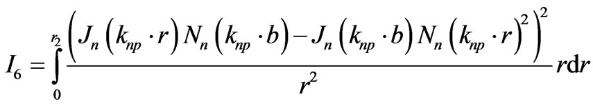
 . The annular ring will be divided into two regions. The field equations for the analysis are given by equations [8]. The expression of input impedance is given by [11].
 (1)
(1)

Figure 1. Geometry of asymmetrically loaded annular ring antenna.
The probe can be located in any of the two regions which are formed due to the location of posts at point c and the boundary conditions at two regions are given.
Probe in region I

 (2)
(2)
2) Probe in region II

 (3)
(3)
where Z0 is the impedance per unit length of the shorting post and is given in [12]. We consider that the probe is located in region I. For eigen-modes denoted by n = 0 or when , the asymmetric modes designated by
  are not generated. The resonant frequency of asymmetric loaded antenna is described in [5], the equation is given by
 (4)
(4)
Solving various equations

where  is a constant and is calculated from equation gives a relation where
  and
and  are defined later in the paper.

In order to evaluate the constant , the normalization condition [13] is used.
 (5)
(5)
Since the entire volume is split into two regions, the normalization condition for the problem under consideration assumes the form
 (6)
(6)
Substituting various values the normalisation constant is obtained.

In the above equation
The different parameters appearing in expression for input impedance (1) assumes the following form
 (7)
(7)

 (8)
(8)
From this
 (9)
(9)
where surface resistance Zs is given as

 and
and

The various constants appearing in Equation (1) is calculated by using the below given equations.
 (10)
(10)
The expression of A corresponds to the copper loss in the microstrip. Due the presence of metallic post an additional component of power loss in the post needs to be added to the conventional copper loss component. Ppost corresponds to the power lost in the conducting post and is given as
 (11)
(11)
In the above expression Z0 is of the form  and
and where
where
 (12)
(12)
The equations of excitation in two different regions of annular ring antenna are given in [14,15]. Using these formulations and using various constants the expressions for input impedance are calculated.
Excitation Probe in Region I
 (13)
(13)
Excitation Probe in Region II
Therefore
 (14)
(14)
Equations (13) and (14) give the input impedance of loaded annular microstrip patch antenna for different probe locations.
3. Results
The posts are loaded asymmetrically on the annular ring antenna. The antenna is fed at region I. For analysis of resonator, the dimensions chosen are a = 30 mm, b = 60 mm, c = 50 mm, h = 1.59 mm, P =1and 2,  r0= 35 mm (feed location), ∆ = 1 mm. The posts are loaded asymmetrically and the resonant frequency is independent on the angular location of posts. Figure 2 and Figure 3 show the variation of input impedance for first dominant mode with frequency. The graph clearly shows that the numerical and simulated results are in agreement and the error in prediction is 2%-3%. Figure 4 shows the variation of return loss with frequency. Here again the results match with each other and it shows that the 10 dB bandwidth is increased when the annular ring antenna is loaded. The method generated is quite simple and accurate to determine the input impedance of asymmetric loaded annular ring antenna. In Table 1, some more parameters like quality factor and efficiency are numeri-

Figure 2. Comparison of present theory with simulated data: Input Impedance with frequency (a = 30 mm, b = 60 mm, c = 50 mm, h = 1.59 mm and P = 1).
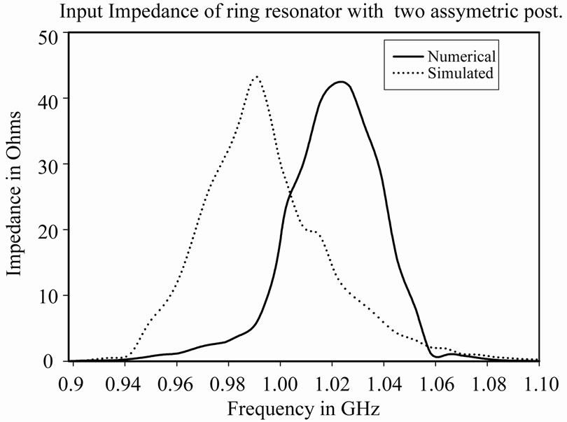
Figure 3. Comparison of present theory with simulated data data: Input Impedance with frequency (a = 30 mm, b = 60 mm, c = 50 mm, h = 1.59 mm and P = 2).
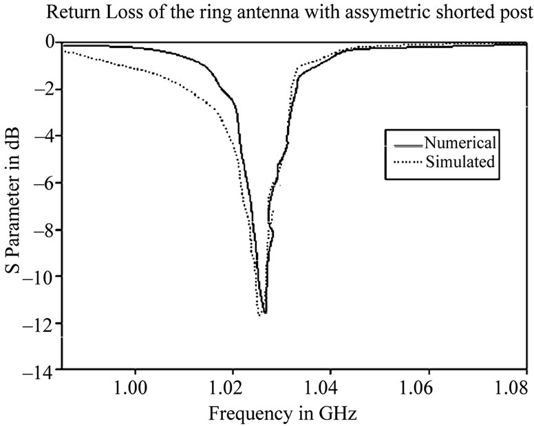
Figure 4. Comparison of present theory with simulated data: Return Loss with frequency (a = 30 mm, b = 60 mm, c = 50 mm, h = 1.59 mm and P = 1).
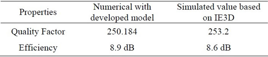
Table 1. Comparison of the numerical and simulated properties of the asymmetric loaded antenna.
cally calculated using the developed model. The model is justified by the comparing the values obtained by present model with the existing standard software results. The shorting posts are one of the methods to enhance the bandwidth of microstrip antennas. The method can be further used to design broadband microstrip antennas using stubs and varactor diodes. The geometry can be further improved by making array of these antennas.