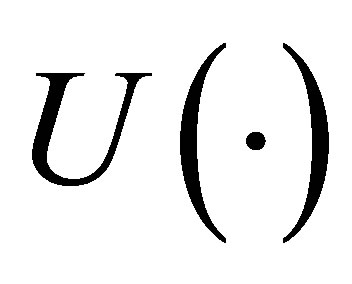
Dynamics and Synchronization of Memristor-Based Fractional-Order System ()
1. Introduction
Since professor Chua predicted the fourth basic element “memristor” [1], it took until 2008 for the element to be demonstrated its existence [2]. A memristor device in nanotechnology based on TiO2 thin film was implemented in Hewlett-Packard (HP) labs, followed by several other materials and methods [3-5]. And this kind of device may be expected to reform the future computers by using it in place of random access memory (RAM). After this landmark work [2], the increasing researches in this topic from many perspectives such as the nonlinear dynamics and chaotic circuit based on memristor, delayed switching in memristor and memristive systems, memristive neural networks are emerged in [6-10]. However, only a few papers involving the memrisor-based fractional order system have been reported so far, and the research on synchronization of fractional order memristive system is even less. For example, a fractional order Chua’s circuit with a memristor and a negative conductance have been studied in [11], and the synchronization based on memristor but limited to integer-order system has been investigated in [12] due to its potential applications in secure communication. In this paper a new memristor-based fractional order system is investigated. Furthermore, it clearly shows the detailed variation of the memristor’s impedance as time goes. Most importantly, the synchronization of memristor-based fractional order systems is achieved between two systems with different nonlinear dynamic properties originally.
The rest of the paper is organized as follows: in Section 2, a memristor-based fractional order system model is depicted. In Section 3, some illustrative examples and numerical simulation results are presented. Finally, the conclusion is drawn in Section 4.
2. Model
Memristor is a nonlinear element. It shows the v-i relationship following Ohm’s law, and the equivalent resistance in HP memristor [10] is depicted by:
 . (1)
. (1)
where  denotes the internal state variable (the width of doped area in the memristor), and
  denotes the whole thickness of the memristor,
  is the equivalent resistance of the memristor with respect to the internal variable.
In Figure 1, the model is derived from the topology of modified Chua’s circuit, where  denotes the conductance of a negative resistor, and
  is a positive linear resistor.
The dynamic in the circuit of Figure 1 is expressed by

Figure 1. Schematic of a memristor-based circuit.
the following state equation as Equation (2):
 (2)
(2)
where R1(H1), R2(H2) denote the equivalent resistances of memristors M1, M2, respectively. And ,
,  are the window functions. There are different definitions about the window functions, such as the Strukov and collegues’ method [2], the Joglekar and Wolf’s method [13] and the Biolek and colleagues’ method [14]. We take the third one in this paper [14] (see Equation (3)).
 (3)
(3)
where  is a step function.
This paper aims at studying the memristor-based fractional order system. By one of the famous definitions of fractional order differential equations—Riemann Liouville (RL) definition [15], the fractional operater is described as Equation (4):
 , (4)
, (4)
Then Equation (2) based on Figure 1 should be extended to the situation of fractional order system.
Let

the memristor-based fractional order system is transformed into a dimensionless form (5):
 (5)
(5)
where the internal state variables h1, h2 of the memristor are still postulated as integer order differential equations.
3. Numerical Simulations
In this section, by using the approximation of fractional operator [16], we work out the solution of the fractional order differential Equation (5) in MATLAB. Figure 2 shows the chaotic dynamic characteristics of the system, where Figure 2(a)" target="_self">Figure 2(a) denotes the three-dimensional (3D) phase trace in x1-x2-x3 space of the fractional order system, Figure 2(b)" target="_self">Figure 2(b) denotes the 2D phase plots of the state variable x3 vs. x2, Figure 2(c) denotes the time evolution curve of state variable x1, Figure 2(d)" target="_self">Figure 2(d) is the phase plot of the state variable x1 vs. h1. We take the common values for some parameters in all the following simulations: the initial condition  and the initial position of the boundary of memristors
 , the fractional order a = 0.9, RON = 100, mv = 10−10, g = −0.0019.
In Figure 2, the other parameters are: C1 = 0.02, C2 = 0.01, L = 1800, r = 1425, ROFF = 15,000.

Figure 2. The strange attractor and time evolution of fractional order memristor-based system (5).
Figure 3 shows the phase trajectories of the memristor-based fractional order system in the various parameters C1, C2, L, ROFF. And in Figures 3(a)-(d), all the phase trajectories show the periodic dynamic properties of the system.