Run-Up Flow of a Maxwell Fluid through a Parallel Plate Channel ()
1. Introduction
In some technological problems related to petroleum industry, Lubrication technology etc., the fluid flow experiences phenomenon viz. run-up which arises due to sudden withdrawal of the pressure gradient causing the flow while its boundaries instantaneously move from rest. Under this phenomenon, steady flow in the unperturbed state gains unsteadiness later. Many research workers have paid attention to the study of Maxwell fluids. In lubrication theory and in many physical situations where we come across slip flows, there arises a class of problems referred to as “run-up and spin-up flows”. The growing importance of the use of non-Newtonian fluids in modern technology and industries has led various researchers to attempt diverse flow problems related to several non-Newtonian fluids. One such fluid that has attracted the attention of research workers in fluid mechanics during the last four decades is the Maxwell fluid. This theory has several industrial and scientific applications as well, which comprise pumping fluids such as synthetic fluids, polymer thickened oils, liquid crystal, animal blood, synovial fluid present in synovial joints and the theory of lubrication (Naduvinamani et al. [1-5], Lin and Hung [6]). Kazakia and Rivlin [7] initiated the study of these flows and later Rivlin [8-10] elaborately studied the run-up and spin-up flows of visco-elastic fluids between rigid parallel plates and in circular geometries. Ramacharyulu and Raju [11] investigated the runup flow of a viscous incompressible fluid in a long circular cylinder of porous material. Ramakrishna [12] discussed the run-up and spin-up flows related to a dusty viscous fluid. Later, M. Devakar and T. K. V. Iyengar [14] examined the run-up flow of an incompressible couple stress fluid between two infinite rigid parallel plates. The flow was assumed to be initially induced by a constant pressure gradient between two infinite rigid parallel plates. After the steady state was attained, the pressure gradient was suddenly withdrawn and the parallel plates were set to move instantaneously with different velocities in the direction of the applied pressure gradient. The time dependence of the resultant flow was investigated. Sugunamma et al. [15] analyzed the start-up flow of an incompressible visco-elastic Rivlin-Ericksen fluid. The initial flow is assumed due to the movement of boundaries. At an instant of time t, the boundaries are suddenly brought to rest and the flow is maintained due to a prescribed pressure gradient. Veera Krishna et al. [16] discussed the hall current effects on unsteady MHD flow of rotating Maxwell fluid through a porous medium in a parallel plate channel. Raji Reddy and Sambasiva Rao [17] analyzed run-up flow of viscous incompressible fluid through a rectangular pipe, a pipe of equilateral triangular cross section, parallel plate channel and a cylinder. They solved them by using ADI numerical technique. Basha [18] extended the analysis of the same by considering visco-elastic Rivlin-Ericksen fluid between parallel plates subjected to a constant suction. Malleswari [19] discussed run-up flow of Rivlin-Ericksen fluid with porous lining. With the recent researches in non-Newtonian fluid flows cited earlier, we consider the flow of an incompressible Maxwell fluid between two parallel plates, initially induced by a constant pressure gradient. The pressure gradient is suddenly withdrawn while the plates are impulsively started simultaneously. The up-flow is referred to as run-up flow. In this present paper, we are studying this flow of a Maxwell fluid.
2. Formulation and Solution of the Problem
Consider the flow of an incompressible Maxwell fluid between two infinite rigid parallel plates y = 0 and y = h along the direction of x-axis (Figure 1). Since the flow is along the x-direction, we take the velocity  , which satisfies the continuity equation.
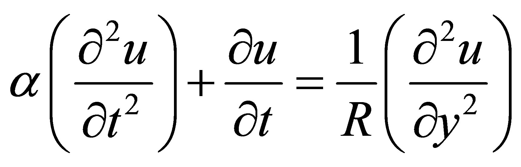
We consider a Cartesian system  so that the fluid flow takes place within boundary plates y = 0 and y = h. The linear momentum equation governing the flow u(y, t) is given by
 (1)
(1)
where  the density, p is the pressure,
  is the coefficient of viscosity and
  is the relaxation time. The boundary conditions are
 (2)
(2)
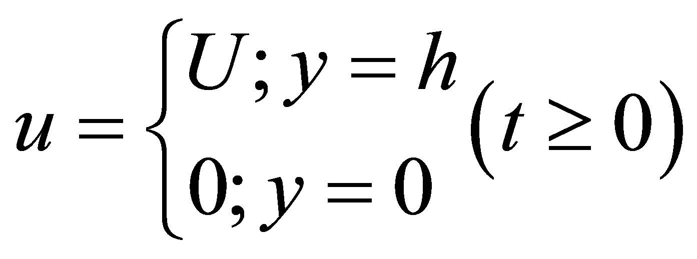
We consider the run-up flow of the Maxwell’s fluid through the parallel plate channel. Initially the flow due to a prescribed pressure gradient with boundaries at rest and at the time t > 0, the pressure gradient is withdrawn and the upper plate moves with a uniform velocity while the lower plate continues to be at rest. The equation gov-
erning the initial flow is
 (3)
(3)
The corresponding boundary conditions are
 (4)
(4)
We introduce the non-dimensional variables

Using non-dimensional variables, the governing equation are (dropping the asterisk)
 (5)
(5)
 (6)
(6)
where, 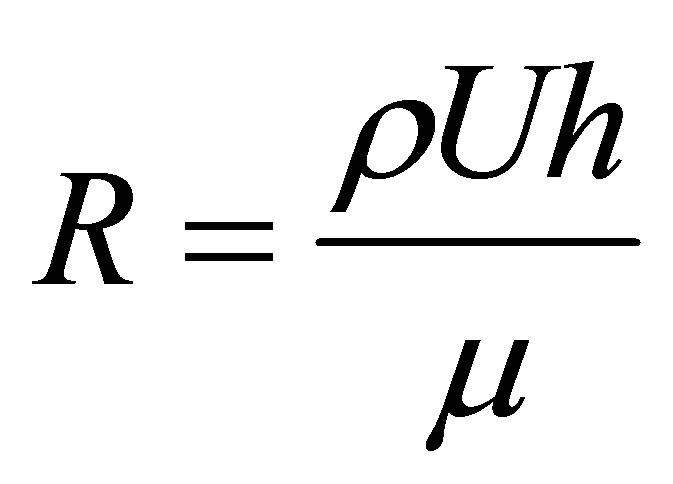 is the Reynolds’s number,
 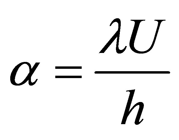 is the Maxwell’s fluid parameter,
  is the constant of pressure gradient. Using the boundary conditions (4), the Equation (6) reduces to
 (7)
(7)
Applying the Laplace transform to the Equation (5) and using the Equation (7), we get
 (8)
(8)
Now the transformed boundary conditions are
 (9)
(9)
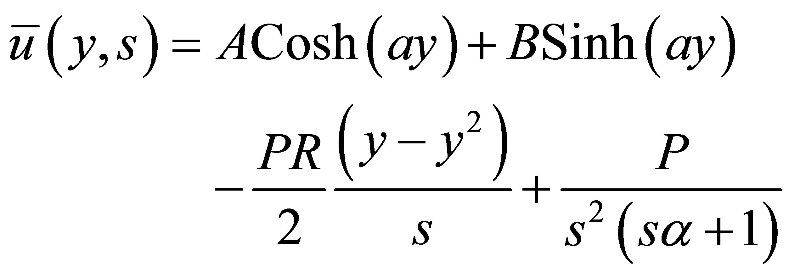
On solving Equations (8) using (9); we get
 (10)
(10)
On taking the inverse Laplace transform [13] for the Equation (10); we get
 (11)
(11)
The shear stresses on the upper plate and the lower plate are given by
 (12)
(12)
and
 (13)
(13)
The mass flux Q is given by
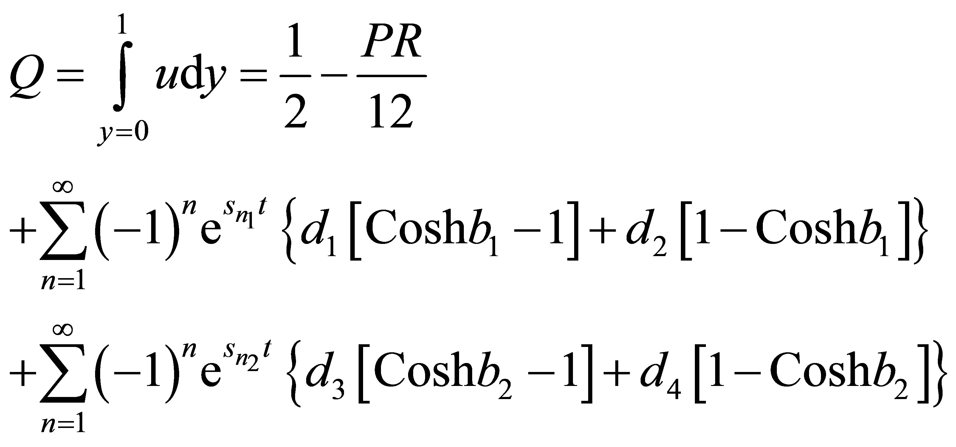 (14)
(14)
3. Results and Discussion
The flow governed by the non-dimensional parameters R the Reynolds number,  the Maxwell fluid parameter. The velocity, the shear stresses on the plates and discharge between the plates are evaluated analytically and computationally discussed for different variations in the governing parameters R and
 . It is interesting to note that the behavior of the flow very much depends on the pressure gradient, in accordance with the run-up flow, the initial steady flow is due to the prescribed pressure gradient, while the perturbed flow is due to the sudden movement of the boundary in absence of the pressure gradient. The flow in direction of the movement of the boundary may be considered as actual flow, where as the flow caused by the pressure gradient assumed to be against the direction of the boundary movement as the reversal flow. Figures 2-9 represent the behaviour of the velocity component u for variations in low and high Reynolds number with Maxwell fluid parameter and for various values of time t. Tables 1-3 show stresses on both boundaries and mass flux.
Figure 2 and 3 depict the variation of the velocity u slightly increases for increase in low Reynolds number R while it experience enhancement with increase in high
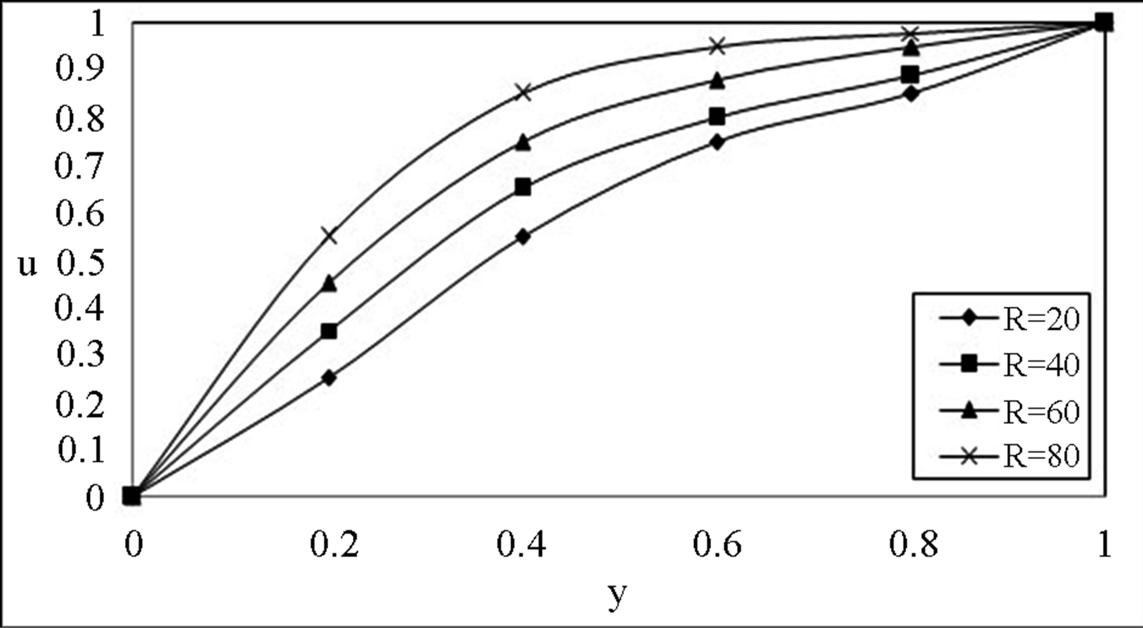
Figure 2. The velocity profile for u on low Reynolds number R with .
.
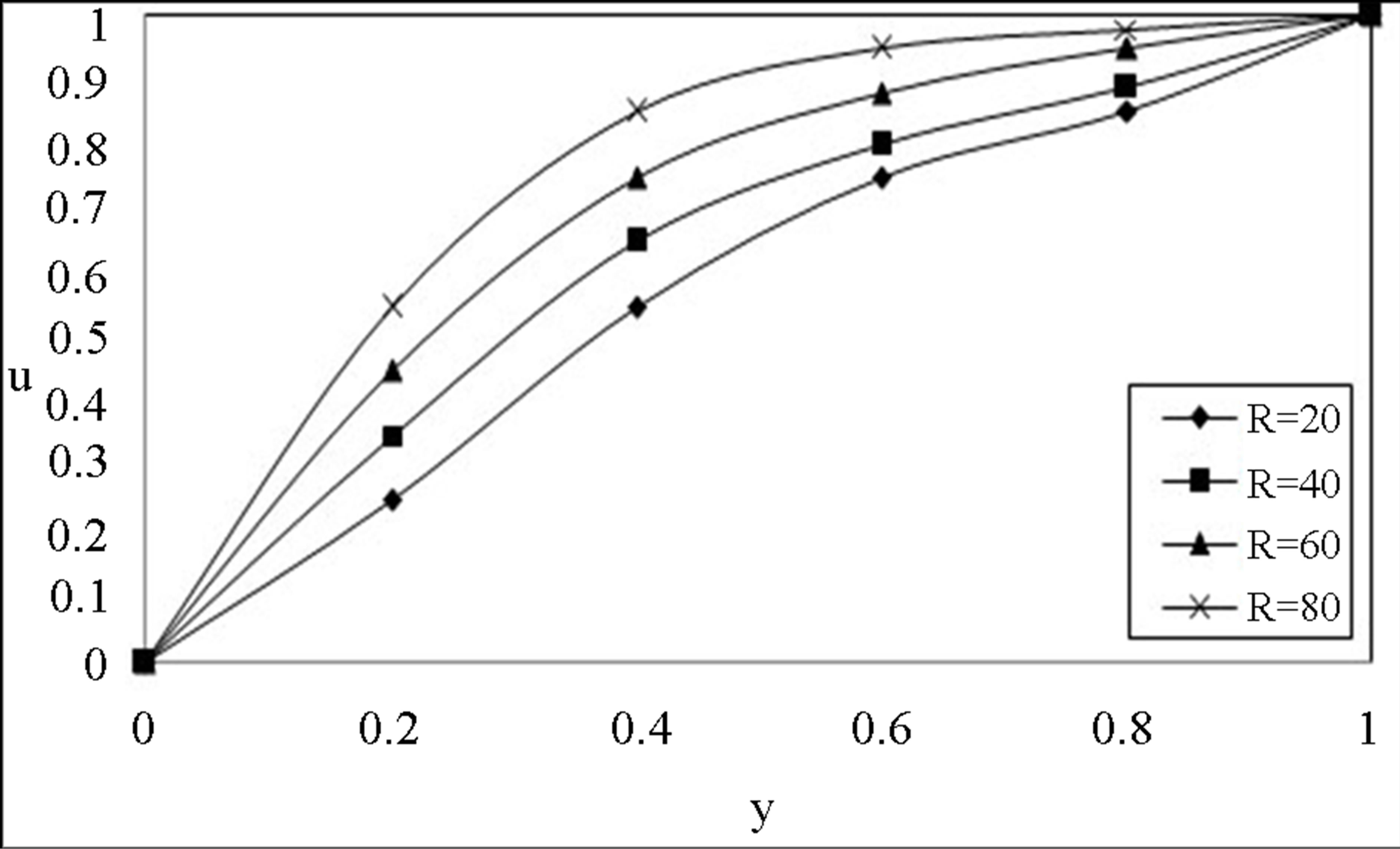
Figure 3. The velocity profile for u on high Reynolds number R with .
.

Figure 4. The velocity profile for u on the Maxwell fluid parameter  with low Reynolds number R = 20, P = 1,

Figure 5. The velocity profile for u on the Maxwell fluid parameter  with high Reynolds number R = 20, P = 1,

Figure 6. Time development of the velocity component u for  with low Reynolds number R = 20, P = 1.

Figure 7. Time development of the velocity component u for  with high Reynolds number
 .
.
Reynolds number being the other parameter fixed. The velocity profiles (4 and 5) for u on the Maxwell fluid parameter  with low and high Reynolds number R = 20 and R = 1000 respectively. The similar behaviour is observed as earlier mentioned. We notice that the Maxwell fluid parameter with the Reynolds number affects the flow in the entire region. An interesting phenomenon is observed in Figures 6 and 7, the magnitude of the velocity enhances with increase in time while fixing R and
 . Figures 8 and 9 indicates that for a fixed t, R and

Figure 8. The velocity profile for u with pressure gradient P on low Reynolds number  with
with .
.

Figure 9. The velocity profile for u with pressure gradient P on low Reynolds number  with
with .
.

Table 1. The shear stresses on the upper plate.
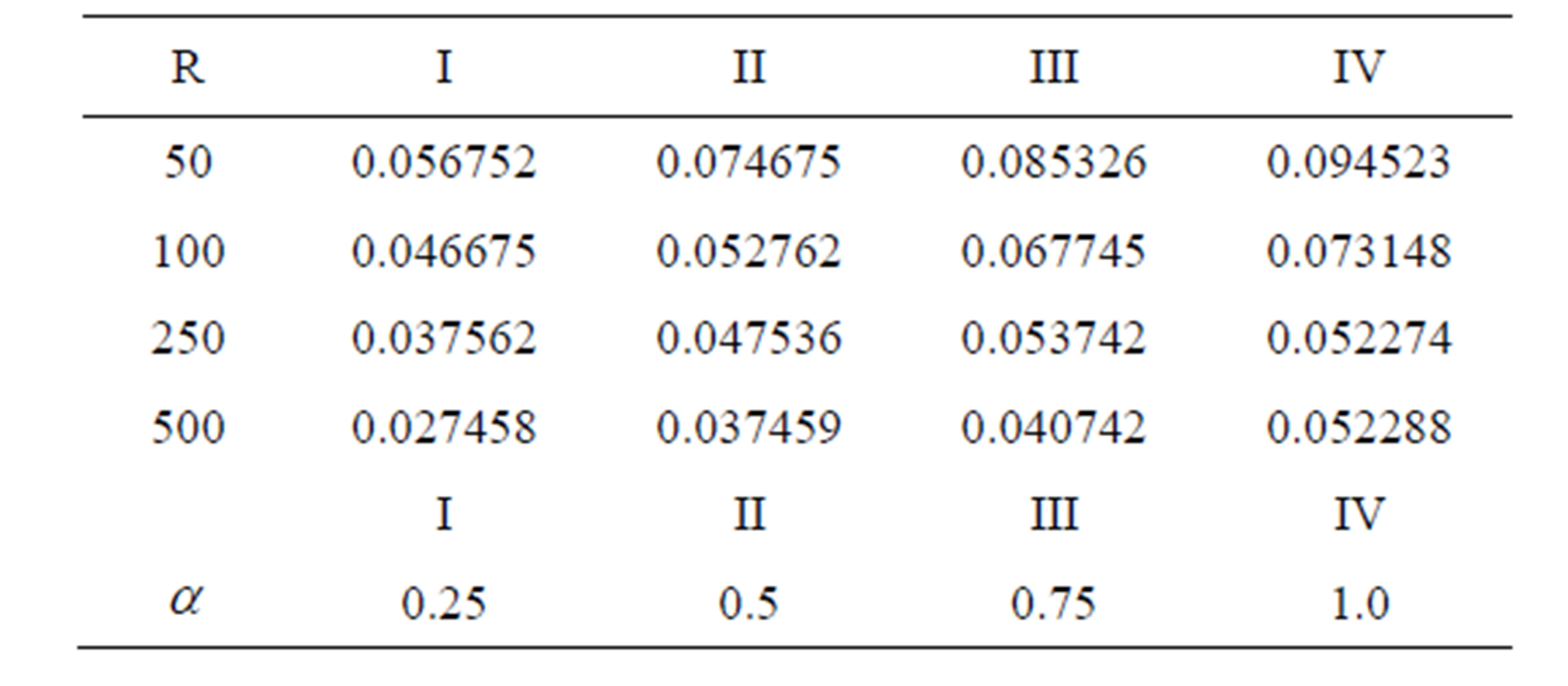
Table 2. The shear stresses on the lower plate.
 , as P increases the velocity decreases for any y. This is in accordance with the fact that an increase in P implies a decrease in pressure which naturally results in a decrease of velocity.
The magnitude of the stresses on upper and lower plates enhance with increasing in , and reduces in

Table 3. The Discharge between the plates.
lower plate increases in upper plate with increasing R (Tables 1 and 2). The discharge between the plates enhances with increase in both R and  (Table 3).
4. Conclusion
The run-up flow of an incompressible Maxwell fluid between two infinite parallel plates is studied using Laplace transform technique. Analytical expressions for the fluid velocity field are obtained in Laplace transform domain. The magnitude of the velocity enhances with the increasing in both R and  and reduces with the increasing in P. The stresses on upper and lower plates enhance with the increasing in
 , reduce in lower plate and increase in upper plate with increasing R. The discharge between the plates enhances with the increasing in both R and
 .
.
5. Acknowledgements
The authors are thankful to Prof. R. Siva Prasad, Department of Mathematics, Sri Krishnadevaraya University, Anantapur, Andhra pradesh, India, and AJCM Journal for the support to develop this document.
Appendix


 ,
,