Decoupling Control Research on Test System of Hydraulic Drive Unit of Quadruped Robot Based on Diagonal Matrix Method ()
1. Introduction
Hydraulic quadruped bionic robot is a walking machinery with the high power weight ratio, fast response and good dynamic performance, which uses the valve controlling hydraulic cylinder system as its drive unit. The overall performance of the quadruped bionic robot is determined by the performance of its hydraulic driving unit. Therefore, it is necessary to test the performance of the hydraulic driving unit which was designed for the quadruped bionic robot [1-5]. A dedicated test system for the hydraulic drive unit of the quadruped bionic robot was built in this paper. The system consists of the subsystem of the hydraulic drive unit and the subsystem of the load simulation unit. The piston rod of the hydraulic cylinders of the two subsystems is rigidly connected. When the input signal of one part makes a sudden change, its output will influence the other part as a load interference and the surplus force is produced. The presence of surplus force seriously affects the precision and dynamic quality of the load simulation. In order to improve the control performance of the test system, it is necessary to eliminate or suppress the mutual interference between the two subsystems [6-12].
In this paper, according to the characteristics of hydraulic drive unit test system, a decoupling control strategy based on the diagonal matrix method was used to control the double inputs and double outputs electrohydraulic servo system [13,14].
2. Composition and Mathematical Model of Test System
2.1. Composition of Test System
Test system is shown in Figure 1. The left part is the hydraulic drive unit which is a position control subsystem, the other part is the load simulation unit which is a force control subsystem. The two parts are rigidly connected together by the force sensor.
2.2. Mathematical Model of Test System
Making the following assumptions to the test system:
1) The oil is incompressible; 2) The oil supply pressure of the servo valve is constant; 3) The oil temperature has no effect on the system performance; 4) Regarding the servo valve as a second-order shock link. Considering the three basic equations of the valve controlling cylinder

Figure 1. Composition diagram of test system.
system: the flow equation of servo valve, the continuity equation of the valve controlling cylinder and the force balance equation of the piston, the open-loop transfer functions of the hydraulic drive unit and the load simulation unit are obtained.
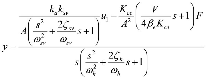 (1)
(1)
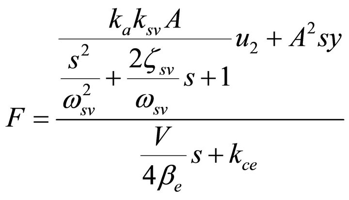 (2)
(2)
In this paper, the subsystem of the hydraulic drive unit and the subsystem of the load simulation unit use two identical systems with servo valve controlling symmetrical cylinder. The parameters of two subsystems are same. They are shown in Table 1.
According to Formulae (1) and (2), the block diagram of test system is obtained. It is shown in Figure 2.
The top half of Figure 2 is the hydraulic drive unit, the other half is the load simulation unit.
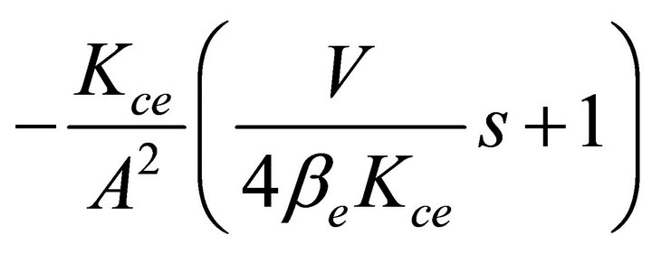 and
and  are coupling loops.
3. Decoupling Control Strategy of Test System
3.1. Research on the Decoupling Theory
The test system of hydraulic drive unit is a double inputs and double outputs coupled system. It belongs to V standard coupled system which was proposed by Mesarovic. The output of each object is influenced not only by the input of its own channel, but also by the other output through the middle channel. In order to eliminate the mutual effect of the position control channel and the force control channel, diagonal matrix method, which was proposed and developed by Boksenbom, is used to achieve the decoupling control in this paper. The algo-
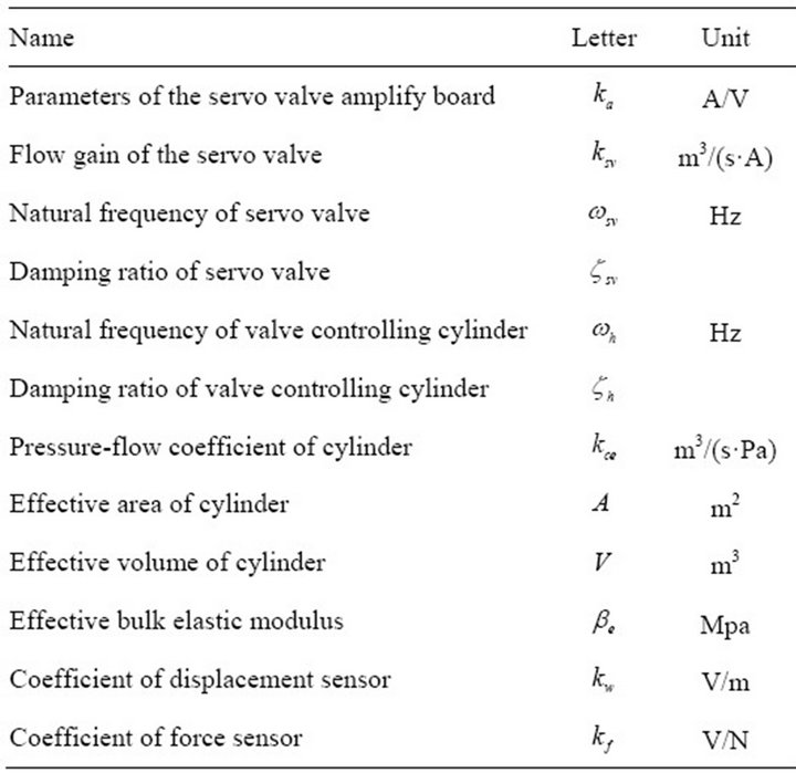
Table 1. Parameters of test system.
rithm of this method is concise, easy to implement and suited for the linear time-invariant systems [15-18].
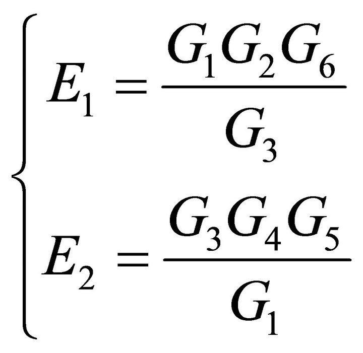
The schematic diagram of decoupling control based on diagonal matrix method is shown in Figure 3. G1 is the transfer function of servo valve of the position channel and G3 is the transfer function of servo valve of the Force channel. G2 is the transfer function of servo cylinder in the Position channel and G4 is the transfer function of servo cylinder the force channel. G5 is the coupling function of the Position channel and G6 is the coupling function of the Force channel. E1 is the decoupling transfer function from displacement channel to the Force channel. E2 is the decoupling transfer function from force channel to the position channel.
The transfer function of the decoupling link is obtained:
 (3)
(3)
Combined with the transfer function of the test system, the transfer function of test system with decoupling link which is shown in Figure 4 is obtained.
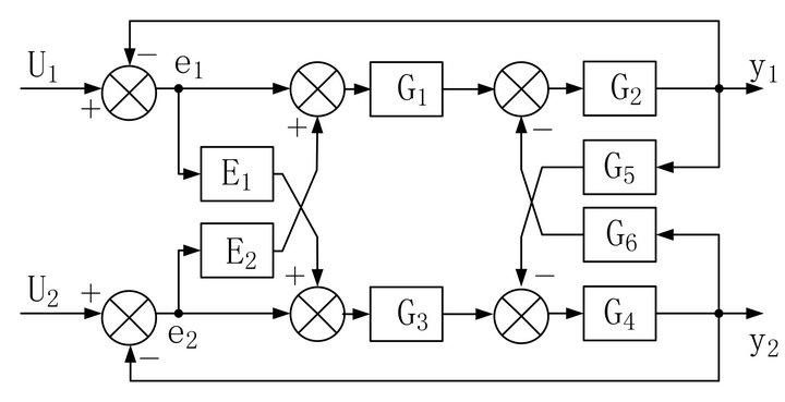
Figure 3. The schematic diagram of decoupling control.

Figure 4. Transfer function of test system with decoupling link.
3.2. Research on the Decoupling Simulation
In this paper, take below situation as the research object. The output power of the force control system is constant, the output displacement of the position control system is changed. By comparing the influence degree of position fluctuation to force control, the availability of the decoupling control is validated.
At first, the AMESimÒ simulation model of test system is built, which is shown in Figure 5. The simulation parameters are shown in Table 2. Set the initial force of the force control system as 7 kN. Start the simulation at 0.5 s with a step displacement signal as the input of the position control system. The simulation results found that when the PID parameters of the position control system are P = 1, I = 0, D = 0 and the PID parameters of the force control system are P = 7 × 10⁻⁷, I = 1 × 10⁻⁴, D =
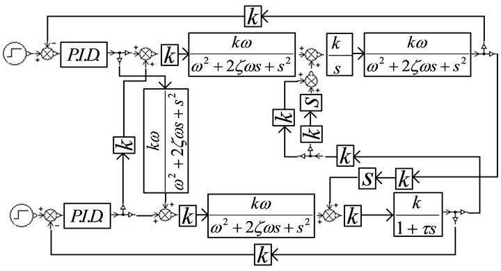
Figure 5. AMESimÒ simulation model of test system.
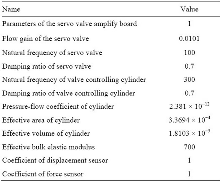
Table 2. Parameters of AMESimÒ simulation model.
0, the control effects of the position control system and the force control system are good. The simulation result is shown in Figure 6.
It can be seen in Figure 6 that the force fluctuation of the force control system is drastic before taking the decoupling control strategy. Its peak reaches 18 kN and it is 2.57 times as much as the given force. The output force increases to the maximum and then decreases and tends to be stable finally. The adjustment time is about 0.2 s. It can be seen that the position fluctuation has influenced the force control system. After taking the decoupling control strategy, the force fluctuation decreases. Its peak reaches 9 kN and it is 1.29 times as much as the given force. The adjustment time reduces to 0.05 s. The output force decreases at first and then increases. The influence of position fluctuation to force control decreases with the decoupling control strategy. But the effect is not ideal enough.
3.3. The Optimization of Decoupling Control
3.3.1. Analysis of the Fluctuation of the Output Force
The essence of diagonal decoupling is adding a compensation link in the system to counteract the effects of in-
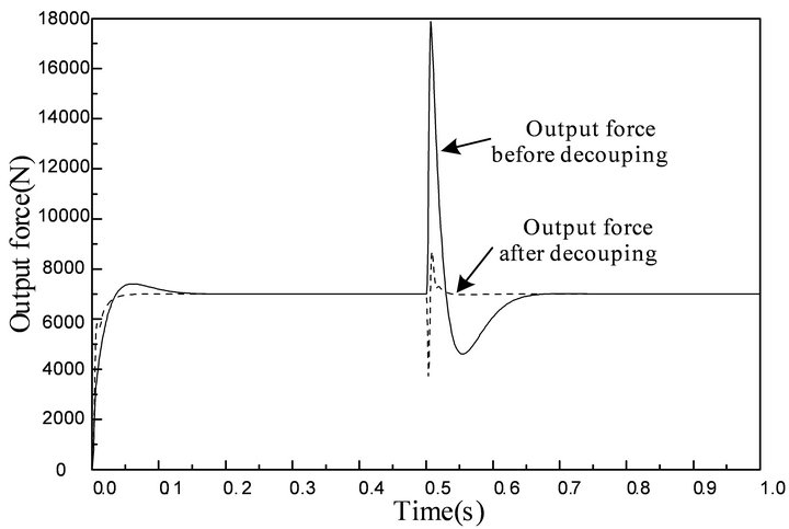
Figure 6. The influence of position fluctuation to force control.
terference loop. The output force of the force channel is controlled by its input, and it is also influenced by the interference channel. It is necessary to add a compensating link to counteract its influence. Diagonal matrix method has been applied to obtain the transfer function from the input of the position channel to force channel which named E1. The block diagram from u1 to F is shown in Figure 7.
3.3.2. The Analysis of the Simulation
The AMESimÒ simulation model of output force from position channel to force channel was built as shown in Figure 8. Start the simulation with step signal valued 25 mm as its input. The simulation result is shown in Figure 9.
It can be seen in Figure 9 that the output force of interference channel is equal to the output force of the compensation channel in the opposite direction. The decoupling link is able to counteract the influence of position fluctuation to force control. But the actual output force fluctuates at the moment of adding the step signal. This is the reason why the decoupling effect is not ideal in the Figure 6. The reason is that the response speed of compensation channel is faster than that of the interference channel.
It can be seen in Figure 7 that the integral element and differentiation element in the interference channel make its response slow. While there is no integral element and differentiation element in the compensation channel. So the integral element and differentiation element in the decoupling link are added and the AMESimÒ simulation model is built as shown in the Figure 10. The simulation result is shown in Figure 11.
It can be seen in Figure 11 that adding the integral element and differentiation element in the decoupling link keeps the response of the interference channel synchronizing with the response of the compensation channel and solves the problem that the output force fluctuates.

Figure 7. The block diagram from u1 to F.
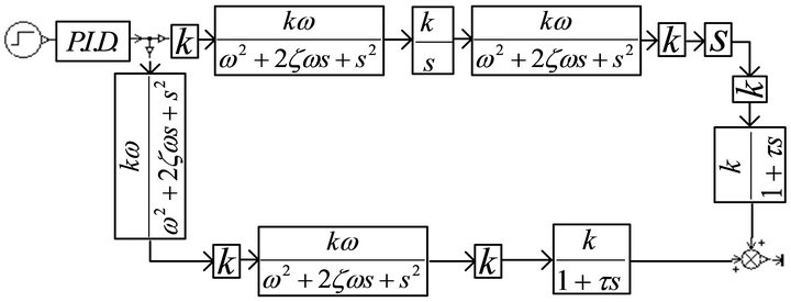
Figure 8. AMESimÒ simulation model of output force from position channel to force channel.

Figure 9. The figure of output force from position channel to force channel.
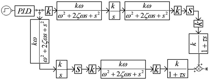
Figure 10. AMESimÒ simulation model of output force from position channel to force channel.
Based on the conclusion above, the integral element and differentiation element are added in the test system. The simulation result is shown in Figure 12.
The simulation result shows that position fluctuation has no effect on force control. The decoupling effect is very good.
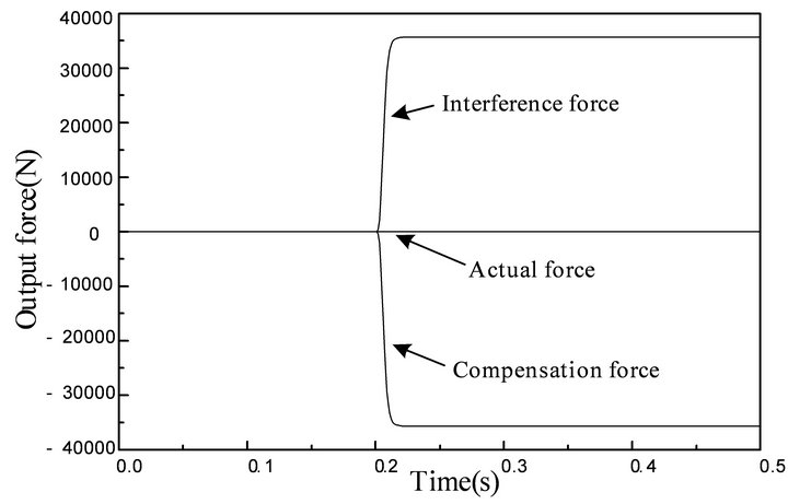
Figure 11. The figure of output force from position channel to force channel.
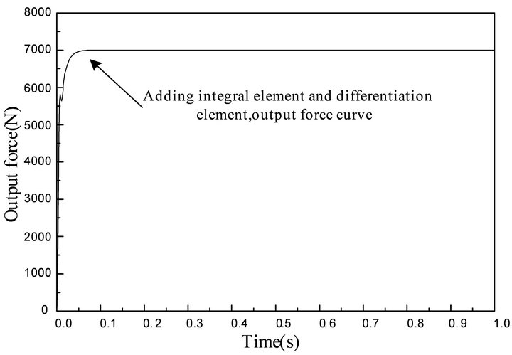
Figure 12. The influence of position fluctuation to force control with decoupling link.
3.3.3. Frequency Response of the Test System
The frequency domain diagram of closed loop from position channel to force channel is shown in Figure 13.
It can be seen in Figure 13 that the gain from input displacement to output force is as high as 120 dB. It shows that the position fluctuation has a great influence on force control. The gain of low-frequency period declines with the decoupling control while the gain of high frequency period is still high with the decoupling control. The fluctuation still existes while the influence of position fluctuation to force control decreases. Adding the
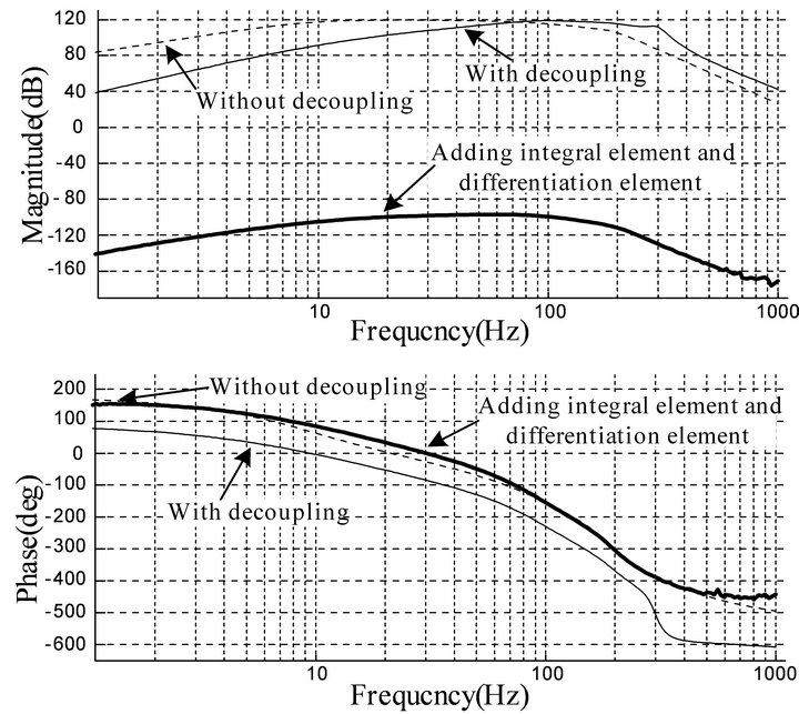
Figure 13. Frequency domain diagram of closed loop from position channel to force channel.
integral element and differentiation element in the decoupling link makes the gain from input displacement to output force under 0 dB. The influence of position fluctuation to force control is eliminated. Above results are the same with results obtained from time domain analysis.
4. Conclusions
The mathematical model of hydraulic driving unit of quadruped bionic robot was built in this paper. Simulation analysis of decoupling control strategy was done and the conclusions are reached as follows:
1) The diagonal matrix method can effectively eliminate the mutual interference between the position control and the force control.
2) The diagonal matrix method cannot completely eliminate the mutual interference between the channels. In order to get better decoupling effect, it is necessary to add the integral element and differentiation element in the compensation link to keep symmetrical and equal with the interference link.
NOTES