Triple Notched Band Characteristics UWB Antenna Using C-Shaped Slots and Slot-Type Capacitively-Loaded Loop (CLL) ()
1. Introduction
Ultra-wideband (UWB) communication systems have become one of the most fascinating wireless topic since the commercial uses of frequency band from 3.1 GHz to 10.6 GHz, was approved by Federal Communications Commission (FCC) in 2002 [1].
However, to satisfy the increasing demand for wireless communication, various ultra-wideband antennas have been studied [2]. But the frequency range for UWB systems will cause interference to the existing wireless communication systems, such as world interoperability for microwave access (WiMAX) service from 3.3 to 3.6 GHz; WLAN in USA (5.15 - 5.35 GHz, 5.725 - 5.825 GHz) and HIPERLAN/2 in Europe (5.15 - 5.35 GHz, 5.47 - 5.725 GHz) [3] and satellite service bands as the International Telecommunication Union (ITU) 8 GHz band and the Satellite Digital Multimedia Broadcasting (S-DMB) band 2.63 - 2.655 GHz [4]. Therefore the UWB antennas with a band-notched characteristic are required. To satisfy such requirement various ultrawideband antennas with notched band have been studied
[5-17]. To introduce such a band-notched function, several methods have been proposed, including embedding a slot of different shapes in the radiating patch, or in the ground plane, using parasitic patches, embedding a slit in the feeding strip, or etching split ring resonator (SRR) coupled to the feed-line [9], or the CSRR (the negative image of SRR) structure [18]. However, the challenge in the band rejection function design is to provide satisfactory skirt characteristics, a sufficient rejection bandwidth and the ability to controlling bandwidth of the notched band.
In this paper, we propose a novel way to design a triple notched band UWB antenna. The four corners truncated in the patch and the partial ground plane with a rectangular slit are used to obtain ultra wideband operating for UWB applications and to increase the operating bandwidth. In order to realize the triple band notch characteristics, two C-shaped slots are embedded in the radiating patch to achieve the twos first rejected bands, and a slot-type capacitively-loaded loop (CLL) to achieve the last notched band.
The simulation is performed using the commercially available simulation software Ansoft High Frequency Structure Simulator (HFSS). The details of the proposed antenna are presented and the simulation of the VSWR and radiation patterns of antenna are also presented and examined.
2. Antenna Design
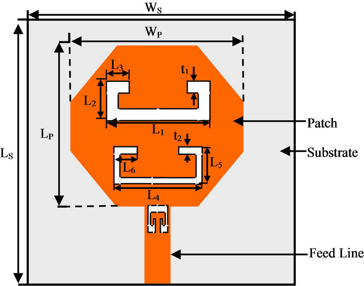
The geometry of the proposed tri-notched bands UWB antenna is shown in Figure 1. This antenna is composed of a square radiating patch with four truncated corners, and a partial ground plane with rectangular slot. The antenna, which has compact dimensions of 20 × 20 mm2, is printed in the front of FR4 epoxy substrate. Its thickness, relative permittivity, and loss tangent are respectively equal to 1.6, 4.4 and 0.02 mm. The microstrip feed line width, is fixed at 3 mm to achieve 50 Ω Characteristics impedance.
The truncated corners dimensions are 8 × 5 mm2. The ground plane dimensions are chosen to be 30 × 11.5 mm2 in this study. The antenna is fed by a 50 microstrip line printed on the partial ground plane.
The first notched band characteristics 3.18 - 3.59 GHz is obtained in this structure, by inserting a C-shaped slot into the radiating antenna patch. The C-shaped slot has total length 34.3 mm and is close to about 0.4λ at the center frequency of the desired notched frequency band (the center frequency of the desired notched frequency band is 3.5 GHz).
The second notched band characteristics 4.70 - 5.88 GHz is obtained, by embedding another C-shaped slot into the patch. The length of this C-shaped slot is chosen to be 21.8 mm which is about 0.4λ at the center frequency of the notched frequency band (the center frequency is 5 GHz).
For the third notched band of 9.54 - 12.22 GHz, a slot type capacitively-loaded loop (CLLs) is introduced in the radiating patch. This slot has a total length of 11.3 mm with 0.4λ at the center frequency of the notched band (10.8 GHz).
The bandwidth and the central frequency of the notched bands can be adjusted easily by proper selection of the parameters of C-shaped slot and slot type capacitively-loaded loop (CLLs).
The electromagnetic software high frequency structure simulation Ansoft HFSS is employed to perform the design and optimization of the proposed.
The final parameters of the antenna are: WS = 30 mm, LS = 35 mm, WP = 20 mm, LP = 20 mm, and LG = 11.5 mm. The dimensions of the C-shaped slots are: L1 = 11.8 mm; L2 = 7 mm, L3 = 4.25 mm, L4 = 9.5 mm, L5 = 3 mm L6 = 3.15 mm, t1 = 1mm, t2 = 0.5mm and the dimensions of the CLLs are: L7 = 2.5 mm, L8 = 2.4 mm, L9 = 1 mm, L10 = 1 mm, t3 = 0.4 mm, t4 = 0.2 mm.
 (a)
(a) (b)
(b) (c)
(c)
Figure 1. Configuration of the proposed UWB antenna: (a) Front view; (b) Back view; (c) CLLs.
3. Results and Discussion
The curve of the simulated VSWR for proposed UWB antenna with and without slots is depicted in Figure 2. As shown in this figure from simulation result, it can observed that the proposed antenna present an impedance bandwidth with good matching for VSWR ≤ 2 from 2.66 GHz to more than 13.5 GHz, which covers the frequency band of UWB band (3.1 - 10.6 GHz) and with triple rejected bands (VSWR > 2). The three notched bands are: 3.18 - 3.59 GHz (VSWR = 13.78 at 3.4 GHz), 4.70 - 5.88 GHz (VSWR = 8.31 at 5.26 GHz) and 9.54 - 12.2GHz (VSWR = 7.77 at 10.94 GHz). Results of the reference antenna without notched characteristics are also shown for comparison. Moreover, it can be observed that adding

Figure 2. Simulated VSWR of the proposed antenna with and without C-shaped slots and CLLs slot.
slots can increases the impedance bandwidth.
The radiation patterns of the proposed antenna in the E and H-plane at 3 GHz, 4 GHz, 7 GHz, 9 GHz and 13 GHz respectively are shown in Figure 3. From the figure, we can see that the simulation radiation patterns of the proposed antenna are nearly an omnidirectional in the E-plane, except for 3 GHz; which makes it a good candidate for UWB devices. While, in the H-plane, the radiation patterns are like dipole radiation pattern, however, these radiating patterns are subject to distortion at high frequencies.
4. Conclusion
In this paper, a new compact planar ultra-wide band
antenna with triple band notch characteristics has been proposed for UWB applications. The notches bands are realised by etching two C-shaped slots and a slot type capacitively-loaded loop (CLLs) in the radiating patch. The proposed antenna is studied and simulated by the Ansoft HFSS. It has a wide operating frequency band of 2.66 GHz to more than 13.5 GHz (VSWR < 2) with three rejected bands of 3.18 - 3.59 GHz, 4.70 - 5.88 GHz and 9.54 - 12.2GHz (VSWR > 2). The radiation pattern of the designed antenna shows good omnidirectional pattern over the operating frequency range, with good notched band characteristic. Accordingly, the proposed antenna is not only expected to find application in various UWB systems, but prevents interference with others communications systems.