Direct Preparation of Hydrogen and Carbon Nanotubes by Microwave Plasma Decomposition of Methane over Fe/Si Activated by Biased Hydrogen Plasma ()
1. Introduction
Hydrogen production from methane is conventionally preformed with following reactions by steam reforming or partial oxidation.
 (1)
(1)
 (2)
(2)
Although the reactions produce CO, it is usually removed by the oxidation to CO2 for the purpose of hydrogen production. However, this is an inconvenient fact to emit large quantities of CO2, greenhouse effect gas. Therefore, the following reaction proceeded by thermal cracking of methane is expected.
 (3)
(3)
According to the thermodynamics Equation (3) can proceed in the range of temperature from 1000˚C to 2000˚C [1]. This temperature is higher than that of general chemical engineering processes. Therefore Ni [2-7], Fe [8,9] and Co [10] based catalyst has been used to decompose methane at lower temperature. Venugopal et al. obtained the methane conversion of 32%, decomposing methane at 600˚C under 30 wt% Ni/SiO2 [4]. Suelves et al. obtained the methane conversion of 67% and hydrogen concentration of 80% at 700˚C under Ni-based catalyst [6]. Shah et al. obtained the hydrogen yield of 80 - 90 vol%, decomposing methane at 700˚C - 800˚C under Fe-M (M = Pd, Mo and Ni) catalyst supported on alumina [10]. In these studies, although the hydrogen concentration is high (80% - 90%), the methane conversion is not so high. Onoe et al. reported that the high selectivities of acetylene and hydrogen are performed with a high CH4 conversion by the microwave plasma technique with following reaction [11].
 (4)
(4)
To obtain higher yield of hydrogen from methane decomposed by microwave plasma, further decomposition of acetylene is necessary. Therefore, the microwave plasma is used together with a catalyst for preceding the following reaction, expecting the resulting carbon become carbon nanotubes
 (5)
(5)
In this study, we investigated that the effect of catalyst treatment time of biased hydrogen plasma on microwave plasma decomposition of methane.
2. Experimental
2.1. Experimental Apparatus
A low-pressure flow type reaction microwave remote plasma apparatus (ULVAC Inc., CN-CVD-100R) was used, which is shown in Figure 1. The apparatus consists of a gas supply unit, a microwave generator, a plasma generator, a chamber and a low pressure unit. Microwaves are generated by an air-cooled magnetron and then introduced into a plasma furnace through a horizontally placed waveguide (height 50 mm, width 96 mm) that complied with the appropriate specifications. Reflected waves were reduced using a three-stub tuner and removed by an isolator.
2.2. Experimental Procedure
Market-grade methane and hydrogen were used. A silicon wafer (10 mm × 10 mm) was used as a substrate, onto which Fe was deposited using RF sputtering at 20 W. The thickness of the deposited Fe was 10 nm. The catalyst was set in the chamber at the position of 650 mm from the wave-guide. The hydrogen plasma treatment involved supplying the catalyst at a flow rate of 80 ml/min and an initial pressure of 180 Pa and exposing it to hydrogen plasma generated by a 500 W microwave under a bias of −150 V at 550˚C from 1 min to 30 min. The mixed gas of 1:4 molar ratios of methane and hydrogen was introduced into the reactor at a flow rate of 100 ml/min and an initial pressure of 254 Pa. This gas was exposed to a 500 W microwave field for 30 min, and then the catalyst was heated under non-biased conditions to 600˚C.

Figure 1. Experimental apparatus for the microwave plasma.
2.3. Calculation of Methane Conversion, Hydrogen Yield, Carbon Yield and Molar Fraction of Output Gas
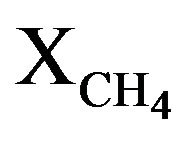
Gaseous products obtained at 30 min of microwave reaction time was analyzed by gas chromatography. From an analysis of gas chromatography, carbon distribution (CD) of output gases and deposited carbon was calculated. Also hydrogen distribution (HD) of hydrocarbon and H2 obtained from CH4 was calculated. Methane conversion ( ) was the total value of the CD of hydrocarbon without CH4 and deposited carbon. The Carbon yield was calculated from the amount of deposited carbon divided by the weight of Fe/Si catalyst.
2.4. Analysis of Products
Output gases were analyzed using gas chromatograph equipped with a TCD detector (SHIMADZU GC-14B, column: SHINCARBON T). The characteristic of the catalyst was analyzed using scanning electron microscopy (SEM; JSM-6300, JEOL Ltd.). The CNTs were analyzed using SEM, transmission electron microscopy ( H-9000, Hitachi High-Technologies Corporation).
3. Results and Discussion
3.1. SEM Image of the Fe Catalyst Surface Activated by Biased H2 Plasma for Various Treatment Time
Figure 2 shows SEM images of surface conditions of Fe activated by biased hydrogen plasma for various treatment times. The catalyst surface becomes rough under hydrogen plasma treatment irrespective of the treatment time, indicating that the Fe surface is modified. For up to treatment time of 1 min, the Fe surface is lumpy, and then it coheres over the treatment time span from 5 to 10 min. After treatment time of 20 min, the surface condition of the Fe produces particles whose sizes decrease with increasing treatment time.
In general, when the catalyst was introduced in a hydrogen atmosphere, catalyst particle sizes increased with increasing of microwave power, catalyst thickness, or treatment time. Chen reported that the Cr surface becomes rough and forms particles whose sizes increase with increasing treatment time, when Cr/Si (Cr thickness: 100 nm) was treated by biased hydrogen plasma (−150 V) [12]. Wang et al. reported the formation of Ni nanoparticles by hydrogen plasma treatment of Ni/TiN/Si [13], and Choi et al. reported that Ni particles were formed by NH3 plasma treatment of Ni/Si [14].
The formation of catalyst particles is different with previous studies because of the different of catalyst metal, catalyst thickness and microwave power with their condi-

Figure 2. SEM image of Fe/Si surface treated for various times by biased H2 plasma.
tions. When Fe/Si was used, Fe was cohered over the treatment time span from 5 to 10 min because the melting point of Fe is lower than that of Cr. The decrease in the size of the catalyst particles for plasma treatment times exceeding 10 min might be caused by etching with the hydrogen plasma.
3.2. Plasma Decomposition of Methane over Fe/Si Activated by Biased H2 Plasma
In order to investigate the effect of catalyst on plasma decomposition of methane,  and hydrogen distribution were compared when the reaction was preceded under non-catalyst or Fe/Si (without treatment).
Figure 3 shows the comparison of  and the comparison of the hydrogen distribution of output gases from CH4, when Fe/Si was not used and Fe/Si was used. In this case, Fe/Si was not treated by biased hydrogen plasma. When Fe/Si was used,
  is slightly decreased from 86% to 83%. The hydrogen distribution of output gases is almost the same value, and carbon was deposited on Fe/Si. Those results found that the both hydrogen and carbon can be obtained using Fe/Si.
In order to active catalyst for the production of hydrogen and deposited carbon, Fe/Si was treated at various treatment times by biased hydrogen plasma.
Figure 4 shows the relationship between treatment time of biased hydrogen plasma and .
.  is slightly decreased from 83% to 76% with an increase of treatment time.

Figure 3. The comparison of methane conversion and hydrogen distribution when the reaction was proceeded under non-catalyst and Fe/Si (without biased hydrogen plasma treatment).

Figure 4. Effect of treatment time of biased hydrogen plasma on methane conversion.
This is probably due to the decrease of catalyst activetion. This factor might be the increase of Fe particle size and deposited carbon.
Figure 5 shows the relationship between treatment time and the hydrogen distribution of output gases from CH4. Hydrogen element of CH4 was mainly distributed to H2 irrespective of treatment time. However, H2 of hydrogen distribution was not increased with an increase of the treatment time of biased hydrogen plasma. This is due to the decrease of catalyst activation by carbon deposition. Hydrogen distribution of C2 hydrocarbon at treatment time of 1min is larger than that at other treatment time. It is probably because reaction mechanism on catalyst is difference of other catalyst.
Figure 6 shows the relationship between treatment time and the amount of deposited carbon. The amount of deposited carbon decreases until treatment time of 5 min.
Beyond treatment time of 10 min, the amount of carbon deposited increases and attains a maximum value (22.0 gc/gcat) at treatment time of 20 min.
Venugopal et al. also reported that the hydrogen yield

Figure 5. Effect of treatment time of biased hydrogen plasma on hydrogen distribution of output gases.

Figure 6. Effect of treatment time of biased H2 plasma on the amount of deposited carbon.
and carbon yield obtained from methane decomposition over Ni/SiO2 indicated the maximum value at Ni particle size of 21 nm in the range of Ni particle size from 17 to 40 nm [4]. The decrease of the amount of deposited carbon at treatment time of 5 min is probably due to the decrease of the activated sites on catalyst by cohering Fe. The factor of the maximum value at treatment time of 20 min is due to the highest activated on Fe/Si surface. It is well known that the methane conversion, the hydrogen yield and the amount of deposited carbon depended on catalyst particle size, and catalyst activation generally decreases by the increase of catalyst particle size. As showing Figure 2, the Fe/Si surface changed with the different treatment time. The Fe has cohered at the treatment time of 5 min, and the surface condition of the Fe produces particles in the range of treatment time from 10 min to 30 min.
3.3. SEM and TEM Image of Deposited Carbon
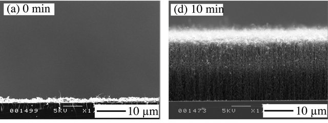
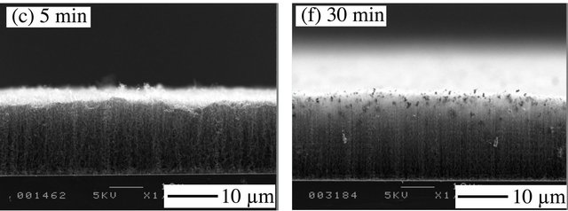
Figure 7 shows the SEM images of the multi-walled CNTs (MWCNTs). When Fe/Si without hydrogen plasma treatment was used, the main deposited carbon forms particle. However, MWCNT growth occurs mainly after the treatment time of 1 min.
Koyano et al. reported that the catalyst was more activated by the plasma treatment [15] and, as discussed above, the surface condition appears to be due to an increase in catalyst activation. The MWCNTs grow to various vertical heights, which is the same result as obtained in the previous studies that formed CNTs on the catalyst substance by microwave plasma treatment [16-19].
The heights of MWCNTs as a function of plasma treatment times are summarized in Table 1. The maximum height of the MWCNTs increases with increasing plasma treatment time, and reaches 30.7 nm at 10 min. This trend is the same as that reported by Sato [19], who observed a maximum height of 11 nm for CNTs prepared on Fe/Si after 10 min of plasma treatment. When using various thicknesses of cobalt as a catalyst, the CNT length decreases with increasing cobalt thickness [19]. Sato used Fe/Si with 70-nm-thick Fe [19]. However here, we used Fe/Si with 10-nm-thick Fe. Therefore, the different MWCNT lengths might be attributed the different Fe thicknesses.
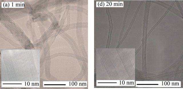
Figure 8 shows the typical TEM images of the MWCNTs, from which we measured the MWCNT diameters. The diameter reaches a maximum value of 22.5 nm at treatment time of 20 min and a minimum value of 9.8 nm at treatment time of 30 min. It is well known that the MWCNT diameter is related to the particle size of the metal catalyst. We have also observed that MWCNT diameters increase with increasing metal catalyst particle


Figure 7. SEM images of carbon nanotubes obtained on the Fe/Si treated for various treatment times by biased H2 plasma.
Table 1. Summary of yield of deposited carbon and the characteristic of CNTs.


Figure 8. TEM images of carbon nanotubes obtained on the Fe/Si treated for various treatment times by biased H2 plasma.
size in the microwave plasma technique [20]. In that study, we measured the Fe catalyst particle size using atomic force microscopy and found that the Fe particle size shrinked from 127 nm after treatment time of 20 min to 95 nm after treatment time of 30 min. Consequently, the different MWCNT diameters in the present study may be due to the change in size of the metal catalyst particle because of the varying treatment time.
The high-magnification TEM image shown in Figure 8 indicates that there are parallel graphite layers between the inner and outer walls of the MWCNTs regardless of plasma treatment time.
However, the number of graphite layers change with plasma treatment time, which suggests that the catalyst particles change as a function of plasma treatment time because it is known that the number of graphite layers depends on the condition of the catalyst, such as whether the catalyst is a particle and the catalyst surface roughness [14,20].
4. Conclusions
Methane was decomposed by microwave plasma with catalyst, which Fe surface condition was activated by biased hydrogen plasma for various treatment times.
 was over 76% irrespective of the treatment time. The hydrogen distribution of output gas was mainly hydrogen (over 60%) irrespective of the treatment time. It is hopeful to increase the hydrogen yield by the further improtant of reaction conditions, especially the property and volume of catalyst.
The amount of deposited carbon was 22 gc/gcat at biased hydrogen treatment time of 10 min. The deposited carbon was filamentous, and it grew vertically on Fe surface and was multi-walled carbon nanotubes. The diameter and graphite layer was difference by biased hydrogen treatment time.
NOTES