1. Introduction
Recently, smart sensors are more widely used in many areas such as in automotive applications; medical applications [1], HVAC applications [2], marine applications [3], civilian applications [4], surveillance missions [5], etc. Integrated circuit based sensors provide low-power, multifunctioning, and computational capabilities since they utilize low power MEMS system that enhance safety, security, medical diagnosis, and reliability of those automotive systems [6-9]. A molybdenum based bi-directional air/liquid flow sensor have been designed [10] utilizing radiation heat transfer in airflow, and convection heat transfer in liquid flow. CMOS technologies can be integrated to provide smart sensors with better anti-interference ability. There are two types of smart sensor structures: digital sensor signal processor and digital control analog signal processor. If analog output signals are needed, D/A convertors are expected at the end of the processing sequence. Security based sensor using carbon nanotube [11] devices may be utilized to detect poisonous gas, resulting from terror attack or others. The low power issue is achieved via low power embedded system processor, while the high speed is achieved via the Zigbee network and compatible wireless boards.
2. Hardware/Software Design
The system used here has been implemented at Smart System Technology Incorporated (SSTI Inc.) [12]. Figures 1 and 2 show the block diagrams of the design, including the PIC18 microcontroller, the sensors used in the project, I2C bus interface, and FPGA chip. The software algorithm that links these sensor components together has been presented elsewhere [13]. The PIC18 microcontroller is an 8-bit processor that runs at 4 MHz. The FPGA program converts the baud rate from one side (PIC controller) to another (Sensor processors), to facilitate transmission in both directors. A baud rate of 35 KHz transmission rate was attained. The program was written by Smart Systems Technologies and is a proprietary material. The diagram shown in Figure 3 can be expanded to include other control circuitries needed for the HVAC system such as air conditioner, dish washer, windows,
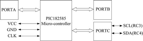
Figure 2. PIC18 microcontroller port setup.
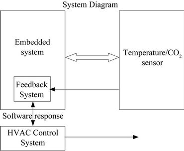
Figure 3. Embedded system diagram (contain CO2/temperature sensor).
switches, doors, air/liquid flow and gaseous sensors for security applications, etc as shown in Figure 4.
3. Results and Discussions
In this project, two sensors were chosen for the implementation and communications with the embedded system. The selection of these sensors was based on their availability at SST Inc. and familiarity with their processors. The SST Inc. provided IUPUI Department of Electrical and Computer Engineering with the hardware components required for the project. The results presented here consist of 3 sets of data. The 1st presents the temperature sensor reading, the 2nd demonstrates the CO2 sensor reading, while the third set of data shows the integrated system response, including both the sensors and the microcontroller. Figure 5 gives the CO2 sensor transmis-
sion and receiving sequence formats. In the transmission cycle, the slave address and relevant configuration bit are written into the CO2 sensor. This is followed by a command byte, start and stop addresses, and checksum byte. The transmission sequence format (see Figure 5(a) is given as follows:
1) Start command;
2) D0 in Hex (7-bit slave address 68 in Hex and 1 read/write bit);
3) 22 in Hex (command number 2 in Hex (ReadRAM), and 2 bytes to read);
4) 00 in Hex (start address of the read procedure);
5) 08 in Hex (end address of the read procedure);
6) 2A in Hex (Checksum 2A in Hex, sum of byte 2, 3 and 4), and
7) Stop command;
8) Delay for at least 20 ms.
Figure 5(b) shows the CO2 sensor receiving sequence. Seven bit slave address and 1 read/write bit are transmitted to the CO2 sensor. The CO2 sensor will then send an operation byte. This is followed by MSB, LSB, and checksum byte, back to the Master (PIC182585). The receiving sequence format as shown in Figure 5(b) is given as follows:
1) Start command;
2) D1 in Hex (7-bit slave address 68 in Hex and 1 read/write bit);
3) Operation byte (this indicates the operation status. Bit 0 tells if the read command was successfully executed);
4) CO2 sensor reading (CO2 sensor high byte: CO2 sensor low byte);
5) Checksum byte, and
6) Stop command.
Figure 6 gives the combined temperature/CO2 sensor integrated system’s readings.
The wireless network setup is given in Figure 7.

Figure 5. Transmission and receiving sequences formats. (a) CO2 sensor transmission sequence format; (b) CO2 sensor receiving sequence format.
4. Gaseous and Bi-Directional Air/Liquid Flow Sensors
A system was designed as shown in Figure 8. The CNT liquid base devices were deposited on copper oxide materials and placed within antenna system where 2.4 GHZ were used for the testing. A computer simulation was performed using ANSOFT software to design the sensor. The system was designed, built, and tested. A range of 2 - 3 MHz shift in frequencies was detected via frequency analyzer, designating the various types of gases. Figures 9 and 10 provide the diagram and setup experiment for the air/liquid flow sensor. Instrumentation amplifiers were utilized to detect a flow rate of 0.005 m/s [10].
5. Sensor Pattern Evaluation
Since the emphasis of this hardware design is to provide security for various applications, it was intended to include smart sensors that detect temperature, CO2, poison gas, and gas/liquid flow magnitude and direction. Recently, high potential applications require signature based

Figure 8. CNT devices on copper oxide substrate used in gaseous sensor design.
testing. This may combine data from various sensors that are fed into software to provide a new set for intention sensors. The work presented here will serve basis of such novel applications. For future pattern evaluation, the design provided here could be tested and evaluated on an

Figure 9. Set up of the bi-directional air/liquid flow sensor.

Figure 10. Experimentally assembled calorimetric thermal mass flow sensor.
existing local police network within a city map. This novel application to local area network has been reserved for future considerations.
6. Conclusions and Future Work
In this work, a smart system board encompassing HVAC embedded system has been implemented. Temperature sensor LM76 and CO2 sensor K22L0 are utilized. The HVAC system has high accuracy and fast response to environmental parameters change. The sensor readings can help to manage the control circuits in real time mode. The results of the overall system indicate that the design criteria were met. In comparison with the current existing devices in HVAC application, this design features high speed response in real time mode, design flexibility in accommodating more sensors, cost effective, and compactness.
For future work, other sensors can be added to the embedded sensor system. This may include optical/electromagnetic sensors, light sensors, pressure sensors, miscellaneous detectors, smoke detector, motion detectorexterior siren, interior siren, glass break and home exits, etc. Another expansion to the proposed HVAC system is to include connections related to internet/Ethernet, telephone lines, and wireless, added to the embedded system. In this expansion, the sensor communication system can be interfaced to a motherboard computer where either Modem or Ethernet card can be used to get a message on the internet or on the cell phone. The alarming signals from the embedded system design can be detected and fed into the motherboard for wireless communications via internet or phone line. In addition, as future work activities, the system can be redesigned to include interrupt service between sensors. With this feature, various parameters can be prioritized according to their importance. After searching various existing technologies, it is found that such gaseous detection using nanotechnology based devices is unique and will be considered further for research.
The software of this work will be available from the Department of Electrical and Computer Engineering, Indiana University Purdue University Indianapolis and can be obtained from the authors of the paper.
7. Acknowledgements
The authors would like to acknowledge the support that the students received from the Integrated Nanosystems Development Institute (INDI) at IUPUI. The authors would also acknowledge Parvin Ghane for her assistance with the ANSOFT software tools.