1. Introduction
This note describes a novel approach to improving antenna bandwidth using a six-element Yagi-Uda array as an example. Developed more than 85 years ago [1,2], the “Yagi” still is widely used, but it is inherently narrowband, to quote: “Usually Yagi-Uda arrays have low input impedance and relatively narrow bandwidth (on the order of about 2%)” [3, p.396]. Modern well-designed Yagis achieve greater bandwidth, on the order of 5% [4] to more than 15% [5], but these bandwidths still are far below the requirements of many wireless systems. The Federal Communications Commission, for example, defines an Ultra Wideband (UWB) antenna as having a fractional impedance bandwidth (IBW) of at least 20%, or an absolute bandwidth of 500 MHz [6, p.15]. Central Force Optimization (CFO) and Variable 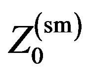 1 technology (Var
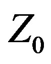 ,
,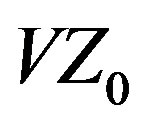 ) are applied to the Yagi design problem, and the array’s IBW performance is compared to another state-of-the-art design. The CFO-
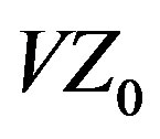 Yagi achieves a very robust IBW of 33.09% for VSWR ≤ 2:1.
2. Yagi-Uda Array
The 6-element array comprises a center-fed driven element (DE) excited by a radio-frequency (RF) source flanked by a parasitic reflector (REF) on one side and four parasitic directors ( ,
, ) on the other. All elements are PEC (Perfectly Electrically Conducting). Three Yagis are described in this paper. Two were optimized with CFO, one using Variable
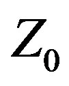 , which treats
 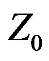 as an unknown variable whose value is to be determined by the optimization algorithm [7,8], and the other using the traditional approach of assigning
  a fixed value (50 Ω resistive in this case). These two antennas are referred to, respectively, as CFO-VZ0 and CFO-FZ0. CFO was selected as the optimization algorithm because it has performed well against recognized benchmark functions and problems in applied electromagnetics [9-18] and is a useful tool for antenna optimization.
The third antenna was optimized with Dominating Cone Line Search (DCLS) [5] and therefore provides a state-of-the-art comparison. The “A3” Yagi, whose dimensions are adapted from in table IV in [5] (REF moved to the Y-axis), was chosen for comparison because it has the largest bandwidth of the three antennas discussed in that paper. Both CFO and DCLS are deterministic algorithms, thus providing the major advantage compared to stochastic algorithms of returning the same results for every run with the same setup.
The Yagis’ performance was computed using NEC- 4.2D (Numerical Electromagnetics Code ver. 4.2 double precision) [19-21]. NEC is a widely used Method of Moments (MoM) wire structure modeling program developed at Lawrence Livermore National Laboratory (LLNL). A freeware version of NEC-2 is available online (source code, executables and a GUI) [22,23]. The modeled antennas are shown in Figure 1 (visualized using 4nec2 [22], the red circle indicating the RF source with the axis length being 1 meter for scaling). Each design’s geometry is quite different.
Table 1 shows element lengths and positions along the boom (+X-axis). Dimensions are in wavelengths,  , at the design frequency,
 . The corresponding NEC input files appear in Figure 2. Because NEC requires dimen-
 CFO-VZ0
  CFO-FZ0
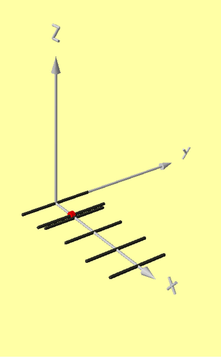
A3 Figure 1. 6-element yagis.

Table 1. Yagi element lengths & boom positions.
sions in meters,  was chosen to be 299.8 MHz corresponding to a wavelength of
  meter. The Yagi designs therefore can be scaled to any frequency because dimensions in meters are in wavelengths at
 . The element radius was set to 0.009097 meter (or
 ) because that value is used in [5]. Note that the design frequency
  and the band center frequency,
  , discussed below are not (necessarily) the same. Even though the array is designed at a particular frequency, the optimized design’s best performance may be (likely is) in a band whose center frequency is different.
3. CFO-Variable Z0
The objective function (fitness) to be maximized by CFO was defined as

where  is the frequency and
  the decision vector defined as

The Yagi optimization problem is 12-dimensional with the following decision variables: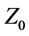 , the feed system characteristic impedance (or source internal impedance if there is no feed line); and the eleven geometric variables corresponding to the Yagi element lengths (“
 ”) and boom coordinates (“
 ”), each subscripted with the corresponding element name (note that REF is placed symmetrically on the Y-axis, that is, at
 ). The fitness increases with increasing forward gain
 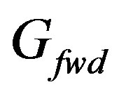 and decreasing
 ,
,  being the voltage standing wave ratio relative to
  (// denotes “relative to”). The fitness is evaluated at three frequencies as shown in Table 2 using the empirically determined coefficients
  and
and .
.  is evaluated in the direction of the + X-axis (θ = 90˚, φ = 0˚ in NEC’s right-handed spherical polar coordinate system). Algorithm details and a complete source code listing are available online [8], and an electronic listing is available upon request to the author (rf2@ieee.org).
The objective function is designed to maximize gain and bandwidth. The term “bandwidth” refers generally to the range of frequencies over which some specific an-
Figure 2. (a) CFO-VZ0; (b) CFO-FZ0; (c) A3.
tenna performance measure is met. For example, “gain bandwidth” is the frequency range over which a minimum power gain is achieved, and so on with respect to other performance measures. IBW is defined as the frequency band or bands within which the antenna input impedance,  ,
,  , is matched to the feed system characteristic impedance,
  , within specified limits. The desired degree of matching can be specified in many ways, for example, in terms of the antenna’s actual input impedance (resistance,
  , and reactance,
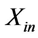 ) as a function of frequency, or, as is more often the case in practice, in terms of a maximum VSWR. IBW typically is specified as
  ≤ 2:1, which is equivalent to a return loss (scattering parameter
 ) approximately less than –10 dB. Other VSWR thresholds can be used instead, and frequently are. Military systems, for example, often use a 3:1 threshold. Zehforoosh et al. [24] describe the design of an UWB microstrip antenna and provide a good summary of
 ’s significance as a design parameter in the context of IBW.
Of course, the antenna designer is free to specify any desired fitness function, and its specific form will produce different antenna designs as a consequence of the different decision space landscape. Some objective functions may introduce  indirectly as a variable quantity, as is done here through the VSWR; or it may be introduced explicitly as, for example, in the bowtie fitness function in [7], where it is variable, or in the second and third objective functions used in [25], where it is fixed.
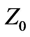
The objective of maximizing IBW is more easily met using Variable 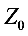 instead of traditional methodology. Var
 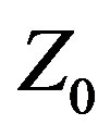 is a new, proprietary (patent pending) paradigm for antenna design and optimization methodology that apparently has been heretofore overlooked. For purposes of discussion the term “design” refers to the process of specifying a complete set of parameters defining an antenna meeting specific performance objectives, while “optimization” refers to specifying a complete set of parameters defining the antenna that best meets specific performance objectives. Methodology refers to the methods, techniques, processes, or procedures traditionally used for antenna design and optimization that treat Z0 as a fixed parameter with a constant value that is assigned at the start of the methodology (even if multiple parametric runs are made). Traditional methodology does not consider
  a variable quantity whose value is determined by the methodology. This distinction is fundamental and quite important. Traditional methodology excludes from the outset all designs that could provide better performance by using some other value of
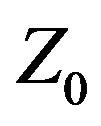 . The A3 array, for example, was designed against
 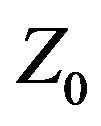 = 50 Ω resistive, but its performance likely would be better with another value. By treating
  as another design variable in the set of variable antenna system parameters to be determined by the methodology, Var
 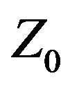 improves on traditional methodology by adding another degree of freedom to the design space or, in the case of optimization, the decision space, thereby making it easier to achieve any particular performance objectives. While Var
  is especially useful for increasing IBW, it can be used to achieve any performance objectives, including ones not involving IBW.
Besides CFO, any number of other commonly employed algorithms, such as Particle Swarm (PSO) [26], Ant Colony (ACO) [27], Group Search Optimizer (GSO) [28], Differential Evolution (DE) [29-31], or Genetic Algorithm (GA) [32] could be used instead. This “product by process” approach applies to any methodology, deterministic ones like CFO; stochastic metaheuristics like PSO, ACO, GSO, DE or GA; analytic approaches such as extended Wu-King impedance loading [14]; or even “seat of the pants” design or optimization based on experience, intuition, or a “best guess.” The specific design or optimization methodology is irrelevant to the novelty and utility of treating 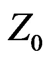 as a design variable instead of a fixed parameter. Var
  can be used advantageously with any design or optimization methodology.
4. Results
Figure 3 plots VSWR for the three Yagis, and Table 3 summarizes the bandwidth data for three different VSWR thresholds (2:1, 2.5:1, and 3:1). In the table, 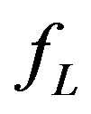 and
and 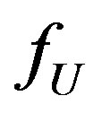 are the lower and upper frequency limits (MHz) corresponding to VSWRs not exceeding the specified threshold, and
  is the bandwidth in MHz. The fractional bandwidth in percent relative to the band center frequency
  is computed as
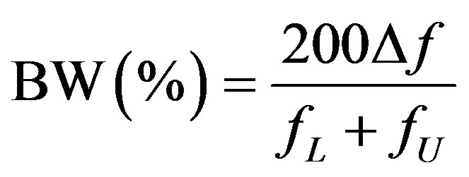 . The CFO-Var
 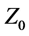 Yagi exhibits
UWB performance (fractional bandwidth ≥ 20%) at all VSWR thresholds, whereas the fixed  antenna is UWB at 2.5:1 and above. The Var
 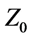 approach increased the Yagi’s VSWR ≤ 2:1 IBW from 19.22% at
 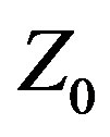 = 50 Ω to 33.09% at
 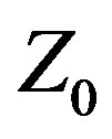 = 107.91 Ω. This improvement is dramatic, and directly attributable to Var
 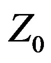 because CFO is a deterministic metaheuristic (the improvement thus cannot be a consequence of an optimizer’s stochasticity). With respect to matching this array to a “standard” 50 Ω feed system impedance, a 2.16:1 impedance ratio broadband transformer or other suitable matching network is required, which easily is accomplished with state-of-the-art matching techniques. By injecting an additional degree of freedom into the traditional antenna design or optimization methodology, Var
  technology has produced a substantially better antenna than the CFO-optimized traditional fixed
 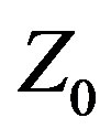 design.
Compared to the CFO-optimized Yagis, the A3 array is considerably more narrowband. Its VSWR ≤ 2:1 IBW is only 15.63%, and it increases only slightly to 17.97% at 3:1. The A3 array’s best IBW performance across all three VSWR thresholds is not as good as the CFO-FZ0 array at its lowest threshold. This is a consequence of the very steep skirts in its VSWR plot. While the CFO-Var 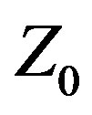 array exhibits similarly steep skirts, as is evident from the plot, its basic IBW is much greater to start.
Figures 4 and 5 plot forward gain (dBi, decibels relative to isotropic) and front-to-back ratio (FBR), respectively [note that in this case directivity power gain are equal because the PEC array elements result in 100% radiation efficiency]. The CFO-optimized arrays have generally flatter gain curves with moderate gain values compared to the A3 design. While the A3’s gain is higher mid-band, the gain bandwidth is narrow, and the gain falls off precipitously with increasing frequency. Both CFO-optimized arrays also exhibit a substantial decrease in gain at the high end of the band, but the drop off occurs well above the highest frequency with acceptable
VSWR. The A3 array has a very high mid-band FBR, but only over a fairly narrow range of frequencies. On either side, its FBR decreases sharply and quickly. The CFOoptimized arrays exhibit more moderate FBR values, but over a much greater bandwidth, with the Var  design performing better than its Fixed
 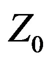 counterpart.
Input resistance and reactance appear in Figures 6 and 7, respectively. The two CFO-optimized arrays exhibit similar behavior for  with moderate values across the band, whereas the A3’s input resistance drops nearly to zero beyond around 310 MHz. For all three antennas, the reactance increases more or less monotonically from about –110 Ω at 200 MHz to between +130 Ω and +130 Ω at 375 MHz. Each Yagi exhibits a single resonance across the entire band.
5. Conclusion
This paper provides an example of applying Central Force Optimization and Variable  technology to the design of a wideband Yagi-Uda array. Even though Yagis are generally considered “narrowband” antennas, the CFO-Var
 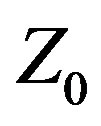 approach produces a Yagi design with good gain and FBR over a fractional bandwidth greater
than 33% with VSWR ≤ 2:1. Variable 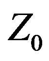 is a new approach to antenna design (patent pending) in which the feed system characteristic impedance (or source internal impedance),
 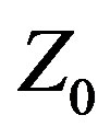 , is treated as a variable quantity whose value is determined by the design or optimization methodology. Variable
 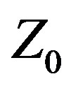 is a heretofore overlooked and fundamentally different antenna design methodology that departs from the traditional methodology of treating
 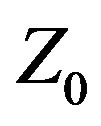 as a fixed design parameter whose value is specified at the outset and never changes. By introducing into the antenna design or decision space an additional degree of freedom, Variable
  makes it easier to achieve specific performance goals, as illustrated by the Yagi design example. While Variable
  should be especially useful for improving IBW, it will be useful in achieving any desired antenna performance objectives, even objectives not involving IBW directly.
NOTES