Conventional Geothermal Systems and Unconventional Geothermal Developments: An Overview ()
1. Introduction
“Geothermal” comes from the Greek words geo (Earth) and therme (heat). This clean renewable energy source is continuously produced deep below Earth’s surface and found both in continents on dry land and also offshore. Geothermal resources have been exploited for thousands of years for bathing and washing, but their uses for district heating and generating electricity developed as an independent industry from the 19th century.
Presently, there is an increased worldwide demand for electricity and heating. At the same, the climate change requires transitioning from fossil fuels to cleaner energies, one of which is geothermal resource, with immense potential. To give a figure of magnitude, the global thermal installed capacity is estimated at 15.9 GW in 2022 but up to 21.3 GW in 2030, e.g. [1] . However, the USGS estimates that in the USA alone the capacity will grow by 2050 as high as 320 GW [2] .
Due to interests in worldwide developments of clean renewable resources, many companies are rapidly attempting new technological developments or expanding their existing ones under the label of “geothermal”. Among them, the Oil & Gas industry plays an active role with technology transfer and investments. As these developments cover various geological conditions, resource potentials, and extraction methods, there are confusions when discussing conventional geothermal resources and unconventional geothermal development alternatives.
To define, conventional geothermal resources have all the necessary conditions of heat, permeability and fluid [3] [4] , thus requiring only drilling to extract the energy up to the supercritical conditions of 374˚C and 221 bar above which the water behaves as gas with highly corrosive fluid. The unconventional geothermal alternatives have the heat, even >374˚C, but not the permeability or fluid, hence necessitating man-made subsurface interventions to capture the heat. However, these categories are presently classified based on widespread features. These range from temperatures [5] [6] , reservoir porosity and permeability [7] , play, heat source and tectonic context [8] , open or closed geothermal systems [9] , power plant types [10] , magmatic or amagmatic heat sources, e.g. [11] , to shallow or deep resources, e.g. [12] , a blend of characteristics from conventional and alternative geothermal developments, and even how petroleum systems are classified.
Reflecting the existing confusions, the International Renewable Energy Agency and the International Geothermal Association [13] point to a lack of worldwide standards and clear resource classifications. They consider that these ambiguities lead to incoherent estimations of geothermal energy potential, reliable energy policy, and assessment of the natural resources among industry players as well as investors.
Indeed, communications from various institutions, working groups and businesses frequently display the confusions regarding the conventional geothermal resources and the alternative developments. A single overview of the main available methods is lacking, besides the overlaps that exist in usage of the same terms for different resources or methods. For these reasons, the natural resources themselves are sometimes classified inadvertently according to the technologies deployed to produce the heat and electricity and not based on the characteristics of the resources. As geothermal is now developed by a range of energy professionals with valuable experience, these deficiencies are disadvantageous when exchanging in view of geothermal project setup and/or scientific collaborations.
As a means of common reference, this paper offers an overview of both conventional and alternative geothermal developments with the following four main topics:
1) Characteristics and terminologies of conventional geothermal resources (Figure 1), and how the geothermal industry has traditionally classified them. We then provide a concise summary of their extraction methods, potentials, utilisations, and even workforce.
2) Compilation and classification of the alternative geothermal developments, with the main technologies advanced by both the geothermal and the Oil & Gas sectors up to this writing (Figures 2-6). Considering that few alternatives are operational and most still experimental, we offer a quick look at their planned utilisations (Figure 7), and required workforce.
3) We also highlight some of the common terms, whose arbitrary usage has caused ambiguity.
4) Finally, the summary of conventional and unconventional geothermal alternatives, and their energy potentials are presented in Figure 8 and Table 1. Along with some concluding remarks, these overviews and means of comparison should contribute towards a common reference for discussions between energy professionals developing geothermal approaches.
2. Features of Natural Geothermal Systems
Geothermal resources are present in all geological contexts. However, conventional geothermal resources are those having favourable parameters in natural state so that the energy can be extracted solely by drilling and fluid self-flow, without needing additional intervention such as injection and heat exchange by fracking or closed-loops. Furthermore, their temperature is less than the supercritical limit of 374˚C above which the water behaves as gaseous corrosive fluid, requiring additional man-made stimulations in such geopressurised conditions. Conventional resources are classified in terms of “geothermal systems”, and before reviewing their classifications, we first provide a non-exhaustive review of their natural features.
2.1. Heat Sources
Geothermal heat sources are threefold: 1) Earth is losing heat at a rate of 4 × 10¹³ W, e.g. [14] due to slow decay of radioactive minerals (e.g., U, Th, and K), causing temperatures up to ~3700˚C in the lower mantle, and a heat flow towards the surface. As a result, temperature increases linearly from surface to depth, defined as normal “geothermal gradients” or “heat flow”. In continental crust (~40 Km thick), the geothermal gradient is typically ~34˚C/Km, but in the 7 Km - 10 Km thick oceanic crust above rising mantle along Mid-Ocean Ridges and in a few spots within continents, the temperature increases by ~66˚C/Km. 2) The decay of radioactive minerals in locally intruded granites at shallow depth of generally < 7 Km. 3) Finally, the molten rock (magma) that forms between the upper mantle (>1300˚C) and the crust can station in shallow magma chambers. When erupting, magma’s temperature is up to ~700˚C during acidic, and ~1100˚C - 1200˚C during basaltic eruptions at the surface. But if magma remains near the surface in chambers, dykes or sills, then it provides the best heat source for geothermal resources. Comparatively, other minor geological and tectonic processes can also generate local and smaller heat flow anomalies such as metamorphism, strain energy released in earthquakes, potential energy in uplifted mountain, earth’s rotation [15] , or even reactivation of older plate boundaries within continents, e.g. [16] .
2.2. Other Natural Parameters
In addition to the heat, geothermal systems require the following parameters.
● Fluids: The medium to transport the heat is either water or steam. The ground water in shallow or deep aquifers is heated by the heat source and boils to become steam. The hot fluid dissolves materials from the rock and becomes enriched in solids and gases, which nature depends on the rock type and reservoir temperature. Geothermal water contains primarily Silica (SiO2) on which basis reservoir temperatures are estimated at depth, but also (S), (Cl), (F), (Na), (Ca), (Fe), as well as (CO2) and (H2S) dissolved gases. In geothermal steam, in addition to CO2 and H2S, other main gases include (H2), (CH4), (N2), and (NH3). When sea water enters a geothermal reservoir, the fluid (called brine), develops a high chloride content. Generally, the fluids in volcanic contexts are dominantly acid (SO4), neutral chloride (Cl), or soda springs (HCO3) e.g. [17] .
● Pressure, depth, and temperature: The reservoir pressure is usually hydrostatic, corresponding to the weight of fresh water column, and estimated at ~10 kPa/m [18] , or 100 bars/Km. The depth of geothermal resources reached by drilling is typically from a few hundred meters to 3.5 Km. Regardless of the heat source and the rock type, temperatures in wells can range from a few degrees Celsius up to the supercritical limit of 374˚C in conventional geothermal resources.
● Boiling curve: To recall the basics, water boils at 100˚C and 1 bar at the surface, resulting in steam separating from water. As the hydrostatic pressure increases with depth, the water needs higher temperature to boil, represented as the “boiling curve”. As example, at a hydrostatic pressure of 80 bars at roughly 1100 m depth, the water needs to be 300˚C to boil and generate steam.
● Heat transfer: Regardless of rock type, tectonic context, or other parameters, there are two ways for heat transfer. One is by “conduction” where there is no fluid transportation but the heat flows from a hotter to a colder surrounding media. Such heat transfer has generally little economical value. The other is by “convection” where cold water descends and the warm water or steam heated by a source ascends to the surface, creating fluid circulation. Convection is the main process in conventional geothermal systems.
● Permeability: Permeable rocks are those that transmit fluid easily. Primary permeability is created after compaction of an original rock where many large well-connected pores remain in the formation such as in sandstone or hyaloclastites. Less or impermeable rocks have finer grains and fewer interconnected pores to ease the fluid flow (e.g., shales, siltstone or granites). Primary permeability increases with porosity, e.g. [19] . Secondary permeability occurs after rock deposition when fractures create new voids for fluid flow (fracture permeability), and permeability is enhanced by fracture density [20] [21] . Permeability, measured in millidarcies (md) [22] , becomes economical in range of 100 to 500 md in sedimentary oil and gas reservoirs e.g. [23] , and 0.1 md to 250 md in geothermal reservoirs within magmatic formations [24] [25] . The permeability of open fractures is in the range of 10 million md [21] , thus infinite [23] . However, parameters such as pressure, fluid viscosity, fluid temperature, stress field, and earthquakes influence the permeability.
● Reservoirs: Geothermal reservoirs are the part of geothermal systems in the subsurface that have sufficient volume of fluid, adequate temperatures, and abundant permeability for direct drilling and exploitation. Reservoir types can be water-dominated, steam-dominated, or a blend of the two phases. In addition, geothermal reservoirs must also be pressurised to yield dischargeable fluid when drilled. Such pressure may be artesian or resulting from boiling of the fluid within the reservoir. Reservoirs can also be classified based on their enthalpy, which is the amount of energy contained in water or steam and measured in kJ/kg. As such, the relevant parameters for reservoir classification are the temperature, pressure, and the state of liquid [9] [26] [27] .
● Recharge: conventional geothermal systems must have a hydrological budget (fluid or steam) by contrast to Enhanced Geothermal Systems as discussed below. The fluid, accumulated in conventional geothermal fields, is mostly groundwater that percolates through porous rocks. In some cases, seawater can enter the reservoir to be heated by the source. In both cases, the recharge zone could be a permeable fracture. The driving force for the water flow into the reservoir is, however, the pressure difference between the incoming cold water and the hotter reservoir fluid. It should be noted that the precipitation of dissolved solids in the fresh or sea water recharge also plays a role especially in sealing off the permeability of fractures. When production is ongoing, geothermal systems can either be “open” when the recharge eventually equilibrates with the mass extraction, or they can be “closed” when the recharge is small or absent, leading to a lack of water in the reservoir [9] .
● Upflow/outflow zones: The reservoir fluid is subject to convection and rises from depth towards the surface, thus creating an “upflow zone” from the reservoir. Such a zone is the primary drilling target in conventional geothermal systems. Near the surface, when the ascending reservoir hot fluid meets the lower-pressured ground water and permeable rocks, it flows laterally as an “outflow zone” that will lay above the colder formations.
3. Classification of Conventional Geothermal Systems
3.1. Resource Types, Tectonic Contexts, and Surface Manifestations
Conventional geothermal systems are defined based on their reservoir temperatures, enthalpy and physical state [26] [27] , regardless of tectonic contexts, sedimentary or volcanic reservoir rock types [3] [4] [6] [27] [28] [29] . Their common classifications, geological contexts and surface manifestations are as follows.
3.1.1. Low-temperature (LT)
With a reservoir temperature of mostly <100˚C and rarely up to 120˚C, they are generally < 3 Km deep, and convective (Figure 1). The fluid has low enthalpy, mostly fresh ground water, but also seawater or saline water circulating in evaporites. LT geothermal water is alkaline, rich in Sodium (Na), Potassium (K), Calcium (Ca), Magnesium (Mg), SO4, HCO3, Cl in both volcanic and sedimentary fields [30] [31] [32] . Because of low enthalpy, surface manifestations can be absent, or weak in the form of warm springs, very mild soil alteration with still fresh vegetation, and some steam. The flow rates of the springs are generally low to moderate (<60 l/s) [33] , while single well capacity is <2 MWe and <5 MW. LT systems can be intra-plate, near or even locally at the plate boundaries.
The heat source of LT resources in faulted volcanic or sedimentary host formations can be a local magmatic intrusion, and the fluid pathways (upflow zones) are generally faults or dykes, carrying the water into the permeable host rock. In the category known as hot sedimentary aquifer (HSA), the heat source is
![]()
Figure 1. Conventional geothermal systems: Low-temperature and hot sedimentary aquifer, medium temperature, and high-tem- perature resources with their magmatic and non-magmatic heat sources.
the normal geothermal gradient or possibly a local decaying radiogenic granite heating the aquifers in permeable rocks, e.g., commonly from Mesozoic carbonates to Plio-Pleistocene fluvial sediments. HSA are mostly in subsided basins (e.g., North of Alpes, Hungary, Utah in USA, Paris and Aquitaine Basins in France, Australia, China). With rock permeability, heat, and fluid, they only require drilling of artesian flowing wells.
3.1.2. Medium Temperature (MT)
MT reservoir temperatures range from 100˚C to 190˚C, and they can be hosted in volcanic [9] , as well as in sedimentary formations [6] (Figure 1). Although their water origin and compositions are identical to LT resources, MT resources have medium enthalpy. Their surface manifestations are stronger, including well-established hot springs (sometimes even boiling), steam, developed altered soil, and damaged vegetation, e.g. [34] . Their flow rates can occasionally reach up to 182 l/s from a single spring such as in Deildartunga of Iceland [33] . Similar to LT resources, these reservoirs are also water-dominated in their upflow zones, e.g. [6] , with a convective system and percolating water circulation through fractures in both sedimentary e.g. [35] , and volcanic terrains e.g. [34] . Their single well capacities are respectively, <7 MWe (2 - 6 MWe) and up to 15 MW.
MT resources have primarily hot intrusions as heat source. The resources are generally found down to 3 Km in continental crust, and 2 to 3 Km depth in oceanic crust, except above a rising mantle where they are as shallow as 1 Km such as in Iceland [9] . MT fields are relatively widespread at both the plate boundaries and intra-plates such as in California and Utah, e.g. [36] , South America, Philippines, Azores, New Zealand, Kenya, Hawai [37] , Europe (e.g., Croatia) [38] , and Central East China [39] .
3.1.3. High Temperature (HT)
HT resources are the most sought-after as their reservoir temperature is 190˚C to 374˚C, and they are high enthalpy (Figure 1). These convective systems are generally found down to 3 Km, and occasionally > 3.5 Km depth. HT resources need conspicuous magmatic heat source provided by active volcanism, as well as high permeability that is usually enhanced by earthquakes. Due to these volcano-tectonic processes, faults and dykes are the critical structures for the fluid flow. Therefore, HT resources are mostly in young porous volcanic rocks at active plate boundaries (e.g., Iceland, Indonesia, East Africa, Turkey, New Zealand), and occasionally in intraplate context above a hotspot such as Yellowstone in the USA.
The fluid in HT resources is either fresh or saline water, rich in silica (SiO2), sodium (Na), chloride (Cl), sulphate (SO4) and calcium (Ca), with CO2, H2S and H2 as dissolved gases [4] [40] . Reservoirs are liquid or vapor-dominated, depending on which phase controls the vertical pressure gradient within the boiling upflow zones, e.g. [41] . Vapor-dominated (dry steam) resources occur when temperature is at or above the boiling point and the prevailing pressure [9] . Examples are the HT reservoirs in the volcanic fields of West Java at 0.5 Km to 2 Km depth [42] [43] , or in Italy’s Larderello down to 3 Km depth with reservoir temperature of 240˚C - 250˚C and 34 bars. On the other hand, boiling zones with 250˚C, also called steam caps, can develop at shallower depths (≤1 Km), overlaying the liquid-dominated upflow zones [41] [44] . Such steam caps generally form as a response to prolonged production drawdown and subsequent pressure decline [9] . HT fields have the most evolved surface manifestations with typical boiling springs, fumaroles, solfataras, steam fields, developed altered soil, and denuded of vegetation. The well capacities are typically 12.5 MW but can go up to 70 MW - 125 MW thermal, and 3 MWe - 25 MWe but as high as 30 MWe - 50 MWe. They are mostly used for electricity generation.
3.2. Resource Extraction
The hot springs have been utilised since long in human history. However, the rising demand for both heat and electricity necessitated extraction by drilling, which developed over recent decades and the hot spring areas became the first drilling targets. As the conventional LT to HT resources do not need additional man-made stimulations, drilling alone yields the hot fluid. LT resources (<100˚C) are by nature artesian and self-flowing, but when the demand is high, downhole pumps may be used to increase the flow and help the extraction of hot water. Extraction of LT resources requires the lightest logistics with drill rig, drill string assemblies, drill bit, pump, cement, water to recover drill chips, and casing from 185/8” near the surface to 95/8” at depth, but no liner, e.g. [45] .
As MT (100˚C - 190˚C) and HT (190˚C to < 374˚C) resources have higher enthalpy, they are of highest economical values. Their ascending fluid boils near the surface and the outflow is a blend of boiling hot water and steam, thus not requiring man-made pumping [4] [46] . As both resources are deeper, hotter and with higher pressure in the reservoir and at the well head, their drilling and extraction require additional logistics such as high-pressure valve at well head, and mud for drilling, cooling and chips recovery. Furthermore, the standard casing is wider (30” to 95/8”) and the wells are protected from collapse by 7” perforated liner down to 3 Km depth [47] . MT and HT wells are drilled both vertically and inclined from the same drilling platform, and used for exploration as well as production. Nowadays, slim holes are drilled more commonly for exploration due to reduced costs of narrower casing (95/8” near the surface to 23/4” down to 1200 m depth).
3.3. District Heating, Rankine Cycles, Power Plant Types, and Pumped Wells
Geothermal district heating emerged in the 14th century in Chaudes-Aigues, France, and from late 19th century it developed with house heating in Idaho, USA. The first electricity from geothermal resource was generated in 1904 in Larderello of Italy, and produced 10 kWe to power five light bulbs. In Iceland, the district heating started in 1930s’ in Reykjavik, and the first electricity was generated in 1969 at Bjarnarflag power plant with a capacity of 3 MWe. Presently, the world largest geothermal power plants for electricity generation are Geysers in California (1.520 MWe installed capacity), Larderello of Italy (1.100 MWe), Iceland (755 MWe), Cerro Prieto in Mexico (720 MWe), Makiling-Banahaw in Phillipines (460 MWe), and Darajat of Indonesia (260 MWe) [48] .
The capacity of conventional geothermal resources determines which power conversion technology is chosen to generate heat and electricity. They range from district heating, pumped wells and Rankine Cycles, to various power plant types. However, geothermal resources are sometimes classified based on these technologies rather than according to the natural features of the resources. Below is an overview of these conversion technologies and the type of geothermal resources they are applied to.
3.3.1. District Heating
With water phase as the fluid and self-flowing wells, LT resources (≤100˚C) are used for district heating although pumping may occasionally be required. Such resources are either in direct use, or require heat exchanger if unfavorable dissolved chemicals are present in the water. As two examples of direct use, assuming a 20˚C ambient temperature and pure water, the thermal energy (MW) produced by a LT well in Australia with 60 l/s flow at 75˚C would be 20 MW for heat [49] , although these estimations are too high. By contrast, in Iceland, the Reykholt geothermal field with a flow rate of 400 l/s at 100˚C yields 109 MW and additional electric power of 3.6 MWe [50] .
3.3.2. Rankine Cycle and Organic Rankine Cycles
Rankine Cycle and Organic Rankine Cycle (ORC) technologies convert a variety of thermal energy to generate primarily electricity, and geothermal resources are the most common source to provide the heat. In addition, the heat that remains in the waste fluid coming out of these processes could be used in space heating.
Rankine Cycle uses steam to generate electricity. A pump pushes the working fluid (water) from low to high pressure; then the high-pressure water is boiled in a boiler to obtain steam. The compressed vapor is then driven through a turbine to generate electricity, and the left-over steam is condensed in a condenser to start over the cycle. The temperature range of the working fluid (water) is generally 125˚C to 150˚C but can be up to 320˚C. However, by increasing the pressure, the working fluid can reach supercritical temperatures in range of 450˚C to 600˚C.
The Organic Rankine Cycle (ORC) is similar to Rankine Cycle, with the difference that ORC uses different working fluid with lower boiling temperature than the water such as refrigerants and hydrocarbons. The ORC uses working fluids of 70˚C to 90˚C.
3.3.3. Power Plants
Power plants produce both electricity and heat, and their type depends on the temperature and the fluid phase of the geothermal resources. There are three main types:
Binary, and/or Flash hybrid power plants are for MT resources, with water-phase reservoir ranging in temperatures between 100˚C and 190˚C. The wells are self-flowing but may require pumping. Individual well capacity for electricity generation is 2 to 6 MWe.
Flash and hybrid power plants are mainly operated in HT fields, with reservoir temperatures of 190˚C to 374˚C where the fluid phases are both water and steam. The wells are self-flowing without requiring well pumping. Individual well capacity for electricity generation ranges from 3 to 25 MWe, and rarely up to 50 MWe.
Direct steam power plants are in HT fields that yield only self-flowing steam with 240˚C temperature. Individual well productivity for electricity generation may reach 50 MWe.
3.3.4. Pumped Geothermal Wells
Pumped geothermal wells have found their niches in geothermal industry, contributing to up to 1000 MWe installed capacity worldwide, e.g. [51] . The approach utilises MT geothermal fluid of 100˚C to 190˚C in binary power plant, and the fluid is maintained in a single liquid phase throughout the production, power cycle, and reinjected back into the reservoir. The working fluids in heat exchangers are recycled and do not come in contact with geothermal fluids.
The largest concentration of geothermal pumped wells is in Nevada with 720 MWe installed capacity from 15 fields and with fluid temperatures of 120˚C to 180˚C, followed by California with 160 MWe installed capacity. Most pumps in Europe are installed in Germany with a total of 47 MWe, followed by Croatia and Hungary with 17 MWe and 3 MWe, respectively. Honduras produces 35 MWe, whilst Turkey has one project with 15 MWe.
3.4. Utilisations
As mentioned, hot springs of lower temperatures have been used for centuries for bathing, washing, and medical treatments. However, in modern times, LT to HT geothermal resources are yielding the heat and electricity for a variety of utilisations (Figure 7).
3.4.1. Classical Utilisations
Lindal diagram provided the earliest summary of utilisations of conventional geothermal resources up to 190˚C [52] (Figure 7). At the time of his classification, the LT resources ≤ 100˚C were utilised for space heating, air conditioning and cooling of buildings and greenhouses, fish and agricultural product drying, aquaculture, swimming pools, snow-melting, and cold storage. Nowadays, LT resources of 20˚C - 90˚C are used for pasteurisation, concrete block curing, fabric dyeing, pulp and paper processing, while the resources with 90˚C to ≤100˚C treated in ORC power plants are used for electricity generation, drying of timber, cement and aggregates. MT resources of 100˚C - 190˚C have been used as saturated steam for electricity generation in binary fluid and conventional electric power plants, evaporation in sugar refining, alumina processing, canning of food, refrigeration by ammonia absorption. MT resources are also consumed for icemaking, as well as ethanol and biofuels production (Figure 7).
Although the Lindal diagram did not reflect the utilisations of HT resources, those resources were used for electricity generation since 1960’s such as in the vapor-dominated Larderello fields (240˚C) and Geysers of California (240˚C) [41] , as well as the Wairakei liquid-dominated field in New Zealand (270˚C) [53] . In recent years, HT geothermal resources of 190˚C to <374˚C are used in flash and dry stream power plants to produce electricity and hot water, as well as for mineral recovery. The by-products of HT geothermal fluids such as silica and salts are utilised in skin care products, while the CO2 extracted as liquid carbon dioxide is used for soft drinks [54] (Figure 7).
3.4.2. Latest Demands in Utilisations
Utilisation of conventional LT to HT geothermal resources is considered by geothermal developers but nowadays also by clean tech companies and working groups from geothermal producing countries such as Iceland, El Salvador, Kenya, and Bolivia in their “Power-to-x” initiative [55] . While these resources provide the energy for classical utilisations, a cascade of new demands calls for intensive electricity availability that can also be supplied by conventional geothermal resources (Figure 7). The main modern utilisations are outlined below.
1) Producing Green Hydrogen
Hydrogen does not exist alone in nature at a commercial level, but requires separation from either fossil fuels or from water/steam [56] . Green hydrogen is classified as clean when it is produced by using other clean energy resources, e.g. [57] . HT geothermal resources > 200˚C play two roles for the hydrogen industry (Figure 7). One is to directly supply considerable power for electrolysis of water in view of hydrogen production. The other is that hydrogen can be also separated from geothermal brine through gas cleaning technologies or through high temperature electrolysis of up to 900˚C hot steam [58] .
Green hydrogen may be consumed in manufacturing ammonia and fertilisers, producing petrochemicals, and in steel industry. In transportation, it can be used either in fuel cells to generate electricity to power up car engines, or directly as a fuel for ships, and possibly as airplane fuel. It could also replace the natural gas network to provide electricity and heat to households, and not the least in “long duration energy storage” (LDES) as hydrogen can be stored for later conversion to electricity (Figure 7). Among the few countries planning to use geothermal resources for producing green hydrogen (and ammonia) are the partnerships of Toshiba Energy Systems, Kansai Electric Power Company, Kanden Plant Co., and Iwatani Co. in Japan [59] , Chevron and PT Pertamina Power Indonesia in Sumatra [60] , Chevron and Mitsui Oil Exploration Co. in Japan [61] , as well as CeraPhi Energy and Climate Change Ventures in the USA [62] .
2) Producing Green Ammonia
Synthetic ammonia is made by using hydrogen from water electrolysis and nitrogen from the air, for which a high amount of electricity is required and could easily be supplied by HT geothermal resources (Figure 7). When this process deploys clean renewables such as geothermal, the ammonia is labelled as “green”. Green ammonia is then used in carbon-neutral fertilisers, decarbonising the food value chain, as a climate-neutral fuel for ships or heavy engines, e.g. [63] , as a replacement for lithium-ion batteries, but also as one of the LDES methods for later use, e.g. [64] [65] . The same companies as producing green hydrogen from geothermal also aim at producing green ammonia.
3) Data centers
Today’s extensive digital needs call for advanced computing systems and data centers for vast amount of data processing, storage and data transmission, cloud computing, artificial intelligence (AI), bitcoin mining, financial services, research, engineering, or aerospace. Data centers thus need both considerable amount of electricity to run the computers and servers but also keep them cool. Not only geothermal energy can readily supply such electricity (Figure 7), but such centers would count as “green data centers” as geothermal energy has low carbon footprint and emissions, thus contributing to the “Net Zero” policy. Examples of companies that are using geothermal resources to power and cool data centers are Verne Global in Keflavik, Iceland [66] , and Rethink Energy in Pisa, Italy that uses the >150˚C MT resources of Larderello [67] .
4) Lithium Mining
Lithium is mostly used to make Li-ion rechargeable batteries for mobile phones, laptops, digital cameras and electric cars, but also in ceramics, glass, lubricating greases, and air purification industries. Lithium mines are mostly in altered rocks of the main producing countries such as Australia, Chile, China, Argentina and Congo. However, Enel was the first company to discover in 1975 that the highly saline geothermal brine of Cesano in Italy has a high lithium concentration [68] . It took almost half a century until interests developed to extract lithium from geothermal brine [69] . Presently, the Australian Vulcan Energy Resources has several partnerships with Volkswagen, Renault and Stellantis to supply them with lithium for electric cars [70] . The company has deep geothermal operations in the Upper Rhine Valley of Germany, as well as permit to study lithium extraction from brine of HT near Cesano, Italy. Controlled Thermal Resources [71] is another company heavily involved in geothermal drilling and lithium extraction from the HT brine of Salton Sea in California (Figure 7). Other countries such as the UK (Cornwall) and France also consider lithium extraction from geothermal brine although their potential is less due to lower temperature of their geothermal resources.
5) Carbon Capture and Storage (CCS)
After capture, CO2 can be stored in deep saline aquifers, deep coal bed methane, or in depleted oil/gas reservoirs. Similarly, MT and HT geothermal reservoirs offer direct or indirect means to store CO2 (Figure 7).
Firstly, CO2 can be injected directly into MT to HT geothermal reservoirs as the same aquifer from which geothermal energy is extracted can also store the CO2 after dissolving it into the geothermal brine [72] . Further advantage of this method is that the same production and injection wells are used, thus reducing the costs of CO2 storage. However, this method requires having already an exploited geothermal reservoir and a functional plant, and only small or medium quantity of CO2 industrial emissions can be stored.
Alternatively, CO2 can be injected into porous sedimentary or volcanic rocks. Particularly young basalts in volcanic areas are the most suitable due to their numerous unfilled pores, and those regions happen to also have available geothermal resources and injection wells. Carbfix in Iceland injects CO2 down to 3 Km depth and estimates that CO2 mineralises in the pores of young basalts over a 3-year time period.
A third method is using compressed CO2 at supercritical temperature of 200˚C and a few hundred bars in Enhanced Geothermal Systems (EGS) [73] instead of water as a working fluid. This method is still experimental and presents challenges, one of which is that in EGS, rock permeability is increased by creating small fractures via injection, but injecting compressed CO2 into those systems could clog the same fractures with time [74] .
3.5. Type of Workforce
Conventional geothermal industry deploys a vast and varied workforce from project kickstart to resource harnessing and utilisation. Prior to initiation and exploration in geothermal projects, major finances are required that call for investors, as well as lawyers to obtain the necessary permits from government authorities and landowners.
The exploration phase needs geologists, structural geologists and mappers, geophysicists, gas and water geochemists, petrologists, reservoir modellers, and technicians. After resource identification, the drilling of exploration wells calls for drillers, rig operators, well completion specialists, wellsite geologists, as well as engineers for road and infrastructure constructions. With successful resource discoveries, the development phase uses the exploration wells or drills new production wells, and deploys similar teams of geoscientists and drillers as for exploration.
The production phase depends on resource temperatures but calls more for engineers than for geoscientists and drillers. For LT resources, civil and mechanical engineers, as well as construction workers are needed for roads and infrastructures, installing well heads and pipelines for district heating, setting up and operating heat exchangers if needed, building and maintaining water tanks, and distributing the hot water in towns. For MT and HT resources, civil and mechanical engineers set up and operate the well heads, separate the steam and water, construct pipelines and transfer the fluid from the well to the power plant. Construction workers, electrical and plumbing, build major power plants for electricity generation, operate turbines, build high-tension power lines for electricity transportation from the plant to users. Especially reservoir engineers and some geoscientists monitor the production rate, the drawdown, and the condition of geothermal reservoirs throughout their life cycle. If hot water is used for district heating, the same workforce as for LT is deployed.
Finally, due to the wide range of utilisations, harnessing conventional geothermal resources also creates jobs for a variety of professionals other than the above technical teams, thus contributing to local economy.
4. Unconventional Geothermal Developments
The climate change and the need for cleaner energies call for additional initiatives to meet the increasing demands for electricity and heat. As a consequence, companies are expanding their existing technologies or developing new ones under the label of “geothermal”. Particularly the Oil & Gas sector is playing an active role in the development of “novel” or “alternative” unconventional geothermal approaches with a transfer of technology and investments.
To reiterate, unconventional geothermal resources have the heat, even above the supercritical conditions of 374˚C and 221 bar, but not the permeability or the fluid. Therefore, the energy cannot be extracted solely by drilling and fluid self-flow, but requires additional stimulations such as heat exchangers, pumps, injection and fracking, or other man-made interventions to deal with corrosive fluid and geopressurised supercritical geothermal reservoirs. Furthermore, unconventional geothermal alternatives may tap into the same heat sources as conventional geothermal resources. However, their aim is to capture the subsurface heat that is beyond the focus of conventional geothermal industry.
The rapid development of unconventional geothermal alternatives has led to confusions in the energy industry regarding the features, potentials, and differences of conventional geothermal systems and unconventional geothermal alternatives. Below, we provide a non-exhaustive overview of the categories of unconventional geothermal developments for common reference.
4.1. Climeon HeatPower Technology
The Swedish company Climeon [75] has developed an ORC called HeatPower Technology to convert waste heat as low as 80˚C, into electricity, and in few cases to use it for district heating. Their ORC technology is designed within single modules that could generate up to 355 kWe electricity and is deployable in many geographies. Multiple modules can be added to increase the capacity up to 1 to 2 MWe. The company uses presently four sources of waste heat (Figure 2).
![]()
Figure 2. Unconventional geothermal alternatives down to 700 m underground depth. Technologies range from surface HeatPower units, heat pumps, HVAC, shallow closed-loops to abandoned mines, and the heat sources from surface heat waste to regional geothermal gradient.
Maritime: Ship’s engines lose 50% of their energy as waste heat, and Climeon’s HeatPower technology uses this waste heat to generate up to 1 MWe on-board ships, which also decreases the fuel consumption by up to 5%.
Power stations: The modular HeatPower units can be added to existing power plants for use of waste heat to generate additional electricity, diversify the energy mix, increase power production, and reduce emissions.
Industrial processes: Many industries produce hazardous waste heat due to their operations. The HeatPower technology converts that unused waste heat into electricity, and at the same time reduces CO2 emissions.
Geothermal: The HeatPower technology has been implemented in various geothermal operations as a complement to power plants, using hot water of 90˚C - 115˚C. As examples, electricity is produced from the waste heat from Japanese spas geothermal wells, or from 2 MWe Japanese binary and flash geothermal power plants. In Iceland, the HeatPower technology has been deployed in a combined heat and electricity production where ORC provides 600 kWe from the geothermal heat in the plant. The geothermal hot water is also cooled down from ~110˚C to 85˚C, or from ~116˚C to 65˚C before being utilised in district heating.
4.2. Closed-Loops
Closed-loops use heat pumps, heat exchangers, or deep borehole exchanger. The popular heat pumps capture the heat of LT resources at shallow depths, while heat exchangers are deployed from near-surface to a few Km depth. Due to their complex technicalities, the deeper closed-loop systems are classified as Advanced Geothermal Systems (AGS) or Advanced Closed-loops (ACL). Below are some of the main closed-loops technologies to date, from near-surface to greater depths.
4.2.1. Heat Pumps and Geothermal HVAC
HVAC (heat, ventilation, and air conditioning) has been around for decades, harnessing the natural ground temperature at very shallow depth for residential and commercial buildings. The heat is extracted from soil (ground-source) or from water bodies (water-source). Both sources are labelled as geothermal heat pumps (GHP), or Geo-Exchange (Figure 2). They require the following three components to work:
1) Closed loop pipes, called collectors or underground heat exchangers, are laid at shallow depths and filled with water and some antifreeze to be heated by the ground or water-sources. In ground-source, the collectors are buried horizontally at 1 - 2 m depth, or connected vertically to shallow geothermal wells at ~100 m depth where heat is extracted via a borehole heat exchanger. In water-source, the collectors are buried at shallow levels in lakes, ponds, aquifers or seas where the water doesn’t freeze in winter or overheat in summer. 2) A ground source heat pump, which works on similar principle as refrigerators, extracts the heat from the fluid in the collectors. In heating mode, the pump compresses the transferred heat to higher temperatures and pushes it into the HVAC system. In cooling mode, the heat is extracted from the air inside the buildings and replaced with the cool air from the ground. 3) The units installed in buildings use the collected energy for cooling, space or water heating, air conditioning, and even electricity in buildings.
Geothermal HVAC systems extract the near-surface heat in range of 10˚C - 21˚C, which is higher than normal geothermal gradient due to the mean annual air temperature of each locality. The benefit of HVAC is that for every 1 kWh electricity used it delivers 3 to 5 kWh heat. The system supplies homes, airports, swimming pools, and hospitals, but can scale up to provide up to 8 MW of cooling and 23 MW of heating. Millions of GHP are already in use in North America and Europe.
4.2.2. Shallow Geothermal
What is labelled as “shallow geothermal” varies between working groups, but it is deeper than the 1 - 2 m depth of geothermal HVAC. However, shallow geothermal partly overlaps with the ~100 m depth-range of geothermal HVAC where heat is extracted via borehole heat exchanger in the ground source (Figure 2).
Depth, geothermal gradient, heat pump, heat exchangers and boreholes are the key parameters of shallow geothermal everywhere. However, different views exist regarding shallow geothermal, as shown by two selected examples from European countries.
The Technical University of Zurich in Switzerland (ETHZ) considers shallow geothermal being down to 400 m depth with exploitable temperatures of 8˚C - 21˚C [12] . The heat is not extracted from a warm aquifer but from the ground- source via geothermal probes, heat pumps at the surface and a system of closed-loop heat exchangers within a borehole, and used for space and water heating, as well as cooling of buildings.
Other professionals consider shallow geothermal to be exploitation of 10˚C - 25˚C heat via two methods [76] . One is similar to ETHZ and uses ground-source heat pump in a closed-loop system to capture the heat solely from the ground down to 400 m depth. In the other, the heat is extracted from warm aquifer down to 500 m in both a closed- and an open-loop system. This latter also includes heat extraction from flooded shafts and tunnels in abandoned mines down to ~700 m depth (Figure 2). The open-loop systems are only used to re-inject the waste water from which the heat was extracted and not to extract the heat. Irrespective of the heat source, i.e., the ground or the aquifer, heat pumps and heat exchangers are used to capture the heat for space and water heating or for cooling of buildings, with a wide capacity from <10 kW to <5 MW.
4.2.3. Greenfire GreenLoop (ACL/AGS)
The North American company Greenfire [77] has, since 2019, developed an AGS called GreenLoop with a pilot project in Coso, California. The technology aims at reaching to 6 Km depth, and to cover a range of permeability and temperatures (70˚C to > 250˚C). This GreenLoop System (GLS) consists of tube-in-tube closed-loop deep borehole pipes inserted into single well (Figure 3), and are a deep heat exchanger (DBHX). They transform non-productive conventional geothermal wells and perform either with GLS or ORC. Heat exchangers in wells are not new; however, the novelty of this GLS is using various working fluids that range from water and supercritical CO2 to organic hydrocarbons (OHR). These fluids are adaptable to GLS or ORC in view of controlling the saturation temperature, pressure, and avoiding scaling. The cold working fluid is pumped down the well via the outer tube and returns hot to the surface via the inner pipe. The heat source would be a hot geothermal fluid in low-permeable formations surrounding the pipes, heating up the working fluid by conduction. Condensation
![]()
Figure 3. Unconventional geothermal alternatives developing down to 7 Km depth in sedimentary and igneous hot dry rocks. These deeper closed-loop technologies are intended for single well, for doublet injection/production wells and multiple boreholes for heat exchange.
occurs on the DBHX, releasing the latent heat of vaporisation, and the condensed fluid descends back to the impermeable reservoir.
The GreenLoop technology can generate electricity and supply direct use as the working fluid has similar potentials as a MT or HT conventional geothermal resource. GLS services for power generation range from retrofitting geothermal well or repurposing Oil & Gas wells, but also in field expansion and greenfield projects such as hydrogen production. The expected amount of electricity from a single well is 2 - 9 MWe as shown by the GreenFire project in Geyser, California. An example of geothermal well retrofit is the production of 2 MWe from a dry and poorly permeable conventional geothermal well in the Mahanagdong field of the Philippines. The direct use of GreenLoop technology would be heating space and water in houses, as well as heating and cooling in data centers (Figure 7).
GreenFire is an initiative by specialists from Oil & Gas sector and benefits from partnership with players such as Baker Hughes and Vallourec.
4.2.4. Eavor Loops
The Canadian company Eavor [78] developed two geo-exchanger closed-loop technologies, similar to a radiator (Figure 3). The prototype was drilled to 2.5 Km in 2019 in Alberta, Canada and developed to a greater depth for commercialisation in Germany. Both Loops have similar principles where two vertical wells, 50 to 100 m apart, are drilled to 4.5 Km depth to exploit heat anomalies in range of 60˚C/Km. After a bend in the vertical wells, 24 lateral wells are drilled in two series of 12 superimposed wells to be in maximum contact with the hot rock, and joined in pairs at the final depth for fluid circulation. Fresh cold water is injected into the upper lateral wells and the hot water returns from the lower lateral wells. A Rankine Cycle converts the energy for use as electricity at industrial scale, leaving heat for district heating.
Eavor Loop 1 is for sedimentary formations where, after a bend of 90˚ in the initial vertical wells, the lateral wells are drilled horizontally, still at 4.5 Km to tap into ~270˚C heat anomalies. Each horizontal well is 2.5 Km long and the total length of the lateral wells is 60 Km. The Eavor Loop 2 is for igneous rocks (e.g., granite) where, after a bend of 75˚, the lateral wells are drilled down to 6.8 Km depth to tap into ~408˚C heat anomalies. The total length of these lateral wells is 90 Km. Toews and Holmes [79] estimate that in this conductive approach, and based on length and depth, the Loop may produce 2.2 MWe. The company, however, estimates that their loops could generate up to 8.2 MWe and 64 MW, enough to heat up to 16.000 homes in their German project.
4.2.5. Chevron and Mitsui ACL Technology
The latest geothermal initiatives in ACL to primarily generate electricity come from the oil company Chevron with two partnerships in late 2022. One is the joint venture of Chevron with Sweden-based Baseload Capital for geothermal opportunities in Nevada, USA. The other is the joint collaboration of Chevron New Energies International and Mitsui Oil Exploration of Japan for an ACL pilot project in Hokkaido to test, de-risk, scale, and commercialise the technology globally [80] .
Chevron/Mitsui ACL technology operates similar to any closed loops as it involves heat exchange at great depth through conduction, similar to a radiator (Figure 3). Their technology drills two vertical wells, one for injection of cold water and the other for return of hot water. The water circulates through connected horizontal wells at depth to capture the heat from the hot rock without extracting hot water (brine) or steam from a conventional geothermal reservoir. The novelty of Chevron/Mitsui is utilising the ACL also as a heat source. However, their technology differs from Greenfire loops that uses downhole heat exchanger in a single well. Furthermore, despite using horizontal wells as heat exchanger, Chevron/Mitsui technology seems not being designed to drill and install 24 lateral horizontal wells, with up to 60 or 90 Km such as in Eavor Loops. As the Chevron/Mitsui technology is a very new development, no details on depth, temperatures, types of working fluid, advantage or disadvantage of this system are yet known.
4.3. EGS and Hybrid Geothermal Systems
EGS stands for “Enhanced” or “Engineered Geothermal Systems”. It is a Hot Dry Rock (HDR) concept in which the bedrock at depth has the heat but lacks either permeability and/or fluid (Figure 4). Cold water is pumped into the HDR via injection wells to create new, or enhance existing fractures (fracking). The water then captures the heat by conduction, and hot water is recovered through production wells. After cooling, the water is re-injected back to the depth for recycling and to repeat the process. EGS operates similar to closed-loops but in EGS fractures play the role of heat exchangers (Figure 4). Notably, in addition to hydraulic reservoir stimulation, permeability could also be enhanced by means of chemical or thermal stimulations.
EGS seems feasible worldwide as long as the heat source (i.e., generally radiogenic granite or intrusion), and cap rocks (usually thick sedimentary formations), are present. The exploitable depth of EGS is 2 Km - 7 Km, and the targeted temperatures range from 100˚C to 300˚C. For lower temperatures of 80˚C to 100˚C, however, a single EGS well is used along with a heat exchanger at the surface, thus making the technique a “Hybrid Geothermal System”.
The aim of EGS is to generate electricity via steam turbines or binary power plants, but also heating (Figure 7). Using the HDR for district heating was first tested in late 1970’s in the Fenton Hill of California, where two reservoirs had a rock temperature > 180˚C at 2.4 Km depth, and a thermal capacity of 4 MW [81] [82] . Later EGS experiments were carried out at Rosemanowes, UK, Basel in Switzerland, and Pohang in South Korea with capacity of <2 MW. However, higher EGS potentials also exist such as in Turkey with estimated temperature of 295˚C at 3 Km depth in Central Anatolia [83] . Although no EGS power plant is
![]()
Figure 4. Unconventional geothermal developments: Enhanced or Engineered Geothermal Systems (EGS) in hot dry rock between 3 Km and 6 Km depth. The method uses mostly fracking to create fractures as natural heat exchangers in rock or adjacent well. The hybrid system uses both EGS and closed-loop as subsurface radiator.
presently producing electricity, many countries are developing their EGS or Hybrid Geothermal Systems, and below are a few examples of those initiatives and techniques.
4.3.1. United Kingdom
The UK drilled a few wells in late 1970s to exploit the geothermal gradient of sedimentary basins and the warm aquifers. Their Southampton project [84] , drilled to 2.1 Km yielded 75˚C hot water to supply 2.2 MW for heating of local houses, hospital and university. The UK also did research on HDR and radiogenic granites, and after decades of hiatus, the country is focusing now on EGS from primarily radiogenic granites of Cornwall in SW England, of North England and of Scotland. The two prominent companies for EGS in the UK are both in Cornwall. They are Geothermal Engineering Ltd and Eden Geothermal Ltd operating, respectively, the United Downs Deep Geothermal Power Project (UDDGP) and the Eden Geothermal Project.
In their UDDGP project, the Geothermal Engineering Ltd drilled an injection well down to 2.2 Km depth, and a production well down to 5 Km (Figure 4), both to intersect the Porthtowan Fault Zone at <1 Km to the west of the site [85] . They encountered nearly 200˚C temperature, with an expected capacity of 3 MWe and 12 MW for various utilisations [76] . Eden Geothermal Ltd also drilled the radiogenic granite in the Eden project site to similar depths as the UDDGP project. However, Eden’s initiative seems to be a Hybrid Geothermal System with combined EGS and surface heat exchanger as the temperatures delivered through the EGS are in range of 85˚C to produce electricity and heat [86] .
4.3.2. Switzerland
Switzerland has been a major player since the 1970’s with its use of near-surface heat pumps for district heating, but reached a total heat supply of 4015 GWh in 2020 from combined heat pumps, borehole heat exchangers, and deep aquifers [87] . Over the past two decades, HDR and EGS have also been a focus, but they were halted in the Basel geothermal project where fluid injection into crystalline rocks triggered earthquakes of ML 2.9 in 2006, followed by post-injection earthquakes of ML 3.4 until 2007 [88] . The project totally stopped in 2009.
Several potential EGS sites exist in both the granites and the sedimentary cap rocks of North Alps and Molasse Basin, targeting a geothermal gradient of 25˚C - 40˚C/Km. The Haute-Sorne is the main project pilot in the Molasse Basin where Geo-Energie Suisse AG plans to drill injection and production wells in the granite to tap 170˚C temperature with a potential of 5 MWe [89] . The wells are vertical down to 3 Km depth, then sub-horizontal to 5 Km depth in order to widen or create fractures. The company plans to drill and fracture slowly, interval-by-interval (Figure 4), to minimise the risk of triggered earthquakes by injection.
4.3.3. North America
Two companies relying on a transfer of know-how and technologies from oilfields represent some of the latest developments in the EGS and Hybrid Geothermal Systems from North America.
1) Sage Geosystems
Sage Geosystems Ltd. [90] and its team of ex-professionals from Shell, ExxonMobil, Weatherford, and General Electric have developed three technologies to produce electricity from HDR. Two of their AGS systems involve EGS and closed-loop (Hybrid Geothermal System), aiming to capture 100˚C - 250˚C from various hot geological formations at 3 Km - 6 Km depths (Figure 4). Their third technology is an underground geothermal battery storage. Some details of their three technologies are:
“HeatRootTM”, developed and tested in 2022 in an abandoned gas well in Texas, is a closed-loop vertical single-well where a local EGS reservoir is created on the side of the well by fracking the HDR (Figure 4). Fluid is pumped down onto the top of the fracture, water circulates inside the fracture and is let to heat up for some time there, then pumped from the fracture into the single well and from there to the surface for electricity production.
“HeatCycle” is an EGS and closed-loop technology that works on the same principle as the HeatRoot fracture but optimises the heat harvesting by drilling 18 to 20 injection/production wells with a movable rig called “walking drilling rig” (Figure 4). These wells act similar to a multicylinder engine and should produce up to 50 MWe. The water undergoes alternating cycles of injection and production, while the fractures act like a balloon, opening as they fill with fluid and closing during fluid flowback.
“Battery+” is a geothermal battery storage technology. The excess electricity produced by solar and wind farms is stored as hot water in the underground HeatCycle wells for later use when demand is high. As the water could remain for a long time underground, it becomes even hotter and thus increases the electricity output.
2) Fervo Energy
The company has developed two technologies, one for electricity production through EGS where fractures act as the closed-loop heat exchanger, and the other for long duration in-reservoir energy storage, or FervoFlex [91] .
To capture the heat from the HDR, Fervo’s EGS technique consists of drilling a set of 3 wells labelled as “horizontal doubled EGS system and deep vertical monitoring well” (Figure 4). The pairs of injection and production wells are drilled from the same pad, starting vertical and bending to horizontal down to 3.4 Km depth within the reservoir [92] . The monitoring well is vertical and is drilled from another pad to 2.4 Km depth. It contains fibre optic sensing for comprehensive data acquisition, as well as monitoring of the flow, earthquakes, reservoir pressure, and downhole gauges. As for Geo-Energie Suisse AG, Fervo creates fractures in multi steps (Figure 4). However, they use a 16-stage plug-and-perforate style stimulation to create a long fracture network connecting the injection and production wells for flow circulation between them. Their fracking induced intensive but controlled micro-earthquakes around the horizontal well, but these micro-earthquakes were well monitored without exceeding M 1.8, and they stopped as soon as injection ended.
Fervo tested its technique from 2020 to 2023 in Blue Mountain of Nevada, USA, tapping some 170˚C at 3.3 Km depth in a poorly permeable reservoir of diorite dykes and sills, with an expected capacity of 63 l/s and 3.5 MWe. The company’s long-term plan is to develop their EGS approach and produce 400 MWe by 2028 and power some 300.000 houses. Fervo has partnerships with academia and the Oil & Gas industry, but also with Google to deploy artificial intelligence and machine learning to improve efficiency of their approach [93] . A pilot project of Fervo and Google in northern Nevada started producing 3.5 MWe in late 2023 to supply power to grid.
In their FervoFlex long duration in-reservoir energy storage, Fervo aims to deliver electricity in response to grid by controlling the flow rate and pressure via charging/discharging cycles in the injection and production wells.
4.4. Heat Recovery from Hydrocarbon Wells and Reservoirs
Until 1990s, Chevron explored and produced conventional geothermal up to 375 MWe in Indonesia, and since 2022 they stepped into unconventional geothermal with their ACL. Except for them, the Oil & Gas industry was not involved in conventional geothermal over the past decades. However, the industry is now transferring its technologies (drill rig on rails and new drill bits) and advanced horizontal drilling techniques to the EGS and closed-loop unconventional geothermal [94] . Additionally, the Oil & Gas industry also considers exploiting the geothermal gradient of sedimentary or radiogenic crystalline fractured oil fields by repurposing hydrocarbon wells or reservoirs. In the UK, the onshore hydrocarbon wells are generally 1 Km - 2.5 Km deep, with 40˚C - 90˚C bottom hole temperatures [95] , but in other countries they can be 3 Km - 3.5 Km deep and up to 120˚C. Below are some of the initiatives by the Oil & Gas industry to extract mainly the heat by repurposing hydrocarbon wells and reservoirs.
4.4.1. Repurposed Oil & Gas Wells
Repurposing Oil & Gas wells has been topic of few pre-feasibility studies worldwide over the past 20 years [96] [97] by both the Oil & Gas industry such as in the UK, e.g. [76] , and by research/industry consortium such as in the European Horizon-2020 MEET Project [98] . The main reason for this repurposing is that the warm brine of hydrocarbon wells might be used to produce heat or electricity instead of abandoning the end-of-life oil wells that could leak methane if not sealed, e.g. [95] . Two techniques are attempted in repurposing the hydrocarbon wells, as follows.
1) Fluids Co-production
The key process in fluid co-production is to pump up the oil and water from many producing oil wells in the same field, and separating the water from the oil in a central facility (Figure 5). The water is then sent to a surface ORC unit for electricity generation, or to a heat exchanger for heat production. After cooling, the water must be reinjected into the reservoir to avoid ground water contamination and to maintain the fluid pressure of the oilfield reservoir. Repurposing hydrocarbon wells, however, has been proven only in small pilot projects, with low output for electricity and heat, e.g. [99] . As examples, China co-produced water (total of 33 l/s and 110˚C) from 8 oil producing wells, generating 310 kWe [100] . In North Dakota, USA, co-producing gas wells yielded a total of 51 l/s and 103˚C water to generate 350 kWe [101] . Vermilion Energy co-produced water (3.2 l/s at 95˚C) from 34 of its oil wells in SW France, generating 16 to 20 kWe [98] .
![]()
Figure 5. Unconventional geothermal development through heat recovery from hydrocarbon wells and reservoirs, applied from 0.2 Km to 3 Km depth. Methods range from fluid co-production from many hydrocarbon wells, to closed-loop in single well, and even recovery of heat from man-made steam after mobilising heavy oil in reservoir. Note that heights of hydrocarbon reservoirs are exaggerated for the purpose of drawing.
2) Closed-Loop in Single Hydrocarbon Well
This technique is similar to any shallow or deep closed-loop system where the fluid circulates in pipes, using either a borehole heat exchanger (BHE) or a deep borehole heat exchanger (DBHE) (Figure 5). A coaxial tube is inserted into a single hydrocarbon well, cold water is injected and circulates to heat up by conduction before returning to the surface ORC unit or to the heat exchanger for heat or power generation. This technique applies to low-temperatures and bypasses the issues of water extraction from, and reinjection into a geothermal reservoir, particularly into a weak hydrocarbon reservoir sandstone where a low reinjection rate may not maintain the reservoir pressure [102] [103] [104] .
DBHE has been around for 3 decades but it has not been widely used in geothermal wells due to its low power and heat outputs. As example, in a 2014 HDR trial project in Cornwall (UK), the DBHE was inserted into a 2.6 Km deep well but generated only ~400 kW with a 7 kWe pumping loss [105] . The idea of using borehole exchangers in single hydrocarbon well for heat and power generation is even newer. As two examples, the project “wells2watts” of Greenfire Energy foresees deploying its heat exchanger in abandoned hydrocarbon wells in addition to non-yielding geothermal wells, e.g. [106] . The UK company CeraPhi is developing its DBHE single-well closed-loop system for heat recovery. Their case study is a 3-Km deep abandoned gas well in North Yorkshire, UK, cased down all the way, with a bottom-hole temperature of 110˚C [107] . CeraPhi expects getting 90˚C hot water, with <1 MW capacity for heating or cooling of 400 homes, swimming pools, or agricultural centers.
4.4.2. Recovery of Man-Made Steam from Heavy Oil Reservoir
Since half a century, the Oil & Gas industry has deployed hot water or steam injection methods to reduce the viscosity of heavy oils or bitumen for recovery. Such reservoirs are at 300 m to 1200 m depth and mainly in oilsands, silts, or shales (e.g., Canada, China, Venezuela, Russia) [108] , but also in some volcanic and igneous formations.
In water injection, the water is heated electrically at the surface; however, its heat content is less compared to steam injection methods [109] . There are three main steam injection methods (Figure 5): 1) In the “Steam Assisted Gravity Drainage” (SAGD), hot steam is injected into an upper horizontal well, the oil flows down by gravity and is produced from another lower parallel horizontal well [110] . 2) “Steam Flooding” (SF) involves continuous steam injection into a vertical well to create a hot zone and drives the heated oil to another vertical well for production [108] . 3) The Cyclic Steam Stimulation (CSS) also deploys vertical wells to pump cyclically high temperature/high pressure steam into the reservoir, stopping and injecting again to reduce the oil viscosity for recovery [110] . The steam for injections comes from heating the water by burning natural gas. The temperature range of water or steam of these methods is 10˚C - 250˚C for mobilising the bitumen, but up to 340˚C for other heavy oils [111] . The length of injection time can vary from several weeks to months and even up to 15 years, thus a long time until the recovery of the heat.
The Oil & Gas industry is now considering to capture the man-made heat left in the reservoirs after SAGD, CSS and SF processes (Figure 5) to use for electricity production (Figure 7), such as by two Canadian companies. To this end, the service company C-FER is adapting its high-temperature electrical submersible pumps, downhole flow control, thermal well casing connections, and a dual-well geothermal powerplant design [112] [113] . In collaboration with the University of Alberta, the ABClean Energy company design [114] plans to use closed-loop in post-blown SAGD heat recovery, along with an ORC to convert the thermal energy into electricity. The feasibility of all above methods is, however, yet to be proven.
4.5. Supercritical and Ultradeep Geothermal
These unconventional developments aim at tapping into hotter resources and/or going deeper (Figure 6). They are labelled as supercritical, superhot rock energy (SHR), ultrahot, superhot geothermal systems (SHGS), superdeep, ultradeep, or heat mining. Their main features are having temperatures in excess of 374˚C and 221 bar [115] , as above these limits, reservoirs do not have water phase but gas, hence a supercritical state. These resources are topics of attentions as they could yield much higher well productivity. They are represented by the three following categories.
![]()
Figure 6. Superhot, superdeep unconventional geothermal developments between 3.2 Km and 20 Km depth. Technologies range from drilling under existing geothermal fields and below brittle-ductile zone, to superhot rock EGS and millimeter-wave drilling with laser beams.
4.5.1. Under Existing Geothermal Fields or Below Brittle-Ductile Transition Zone
Supercritical conditions can be found either at the root of volcanic systems under existing geothermal fields at depths of 3 Km - 7 Km, or below the brittle-ductile transition zone (BDTZ) in the crust. As exploiting such heat requires fracking by injecting cold water, letting the fluid heat up and return hot to the surface, these are deep EGS operations. To learn about these resources, several research projects and a few drilled wells have been carried out worldwide in both compressional and extensional tectonic contexts, as well as in continental and oceanic crust with the support of European Union.
As examples, three EU-supported projects focused on drilling into supercritical conditions under existing volcanic geothermal systems (Figure 6). The DESCRAMBLE Project in Italy that run between 2015 and 2018, deepened a well in the Larderello geothermal field from 2.2 Km and 350˚C to 2.9 Km depth and found 517˚C and 300 bar, e.g. [116] . The project was also a proof-of-concept for drilling technologies. In 2017, the IDDP-2 well in Reykjanes of Iceland was deepened under the DEEPEGS Project from 3.1 Km to 4.5 Km, reaching ~500˚C at its bottom [117] but the well collapsed and was abandoned. The Los Humeros in Mexico has been producing since 1990. From 2016, the collaborative GEMex Project considers drilling deeper into this superhot reservoir, which has some 380˚C potential at around 2 Km depth, and a current capacity of 94 MWe [118] .
In 1995, the Japan Beyond-Brittle Project (JBBP) drilled a well down to 3.7 Km depth into the BDTZ and found >500˚C [119] . Since 2009, the New Zealand “Hotter and Deeper Project (HADES)” is considering the >400˚C and 10 GWe potentials of the BDTZ at 5 Km - 7 Km depth under the Taupo Volcanic Zone [120] .
4.5.2. Superhot EGS/Superhot Rock Geothermal (SHR)
The American company AltaRock Energy [121] has been a geothermal player for the past few decades, focusing on deep EGS since 2009 and with projects mainly in the USA. Their EGS uses typical injection and production wells, but they create permeability by interval-by-interval fracking. This is done by injecting water to open up the fractures, then injecting very small plastic particles to stop the fracture growth before stimulating the next set of fractures at depth (Figure 6). They tested their technology in 2017 at a site just outside the Newberry volcanic caldera in the Pleistocene volcanic complex of Oregon, USA [122] . After 2018, the company deployed its deep EGS technology to a 3.2 Km deep well there, which was drilled into impermeable hot rock with 350˚C but had no hydrothermal fluid. After stimulation by AltaRock, the well delivered steam superheated by 25˚C [123] . The company anticipates generating up to 10 GWe, which they consider enough to power 3 million homes.
Presently, AltaRock focuses on EGS at the 3 Km - 4 Km depths of conventional geothermal drilling. However, in collaboration with American universities and Baker Huges among others, the company is also developing advanced drilling, material and technologies to drill into Superhot Rock Geothermal (SHR) beyond 7 Km depth, particularly in partnership with Quaise Energy, as discussed below.
4.5.3. Deep Millimeter-Wave Drilling
Drilling for hydrocarbons is able to go as deep as 7 Km. Still, the American company Quaise Energy, which grew out of the MIT’s Plasma Science and Fusion Center aims at drilling down to 20 Km [124] where the expected temperatures of 500˚C and 22 MPa [125] are difficult for conventional drill bits.
Quaise’s initiative is a non-EGS approach as it does not create or stimulate fractures. Their concept is using a combination of rotary drilling down to the basement, and from there, directed millimeter-waves down to 20 Km (Figure 6). The laser beams are generated by a 1-MW gyrotron at the surface. The technique of beams is not new as it was deployed in the past decades to heat up plasma, and the gyrotrons have already been developed by the Soviet Russia since 1960s. However, Quaise is using these beams to heat, melt, and pulverise the rock at great depth. A part of the pulverised rock particles solidifies and become glass, acting as a casing to seal fluids, gases and other contaminants from coming into the well [126] . There are no mechanical systems in the wellbore as the long tube to guide the waves constitutes the downhole equipment [126] . While firing the beams, argon gas is pumped down to cool the well and removes rock particles up to the surface. Water is then injected into the hole and returns as super-heated steam of up to 500˚C [127] . As such, Quaise’s approach is a deep closed-loop. However, if during the millimeter wave drilling, the well hits a water-filled fault, the wellbore can be sealed to keep the water behind the glass wall. In case the volume of water is more than it can be sealed, the resource can be used as a conventional geothermal well [127] .
Quaise estimates that drilling down to 20 Km takes up to 100 days [125] , and hopes to reach full drilling capacity by 2024. The company expects to set up its first superhot plant with 100 MWe in 2026. But their main goal is to repower old coal-fired plants by this technique from 2028 [124] . As mentioned earlier, Alta Rock and Quaise collaborate on these SHR projects to overcome the technical challenges.
4.6. Utilisations
This chapter recalls the utilisations described for each of the unconventional geothermal chapters above but groups them in terms of equivalent to or above the LT, MT, HT conventional geothermal resources (Figure 7).
4.6.1. Equivalent to Conventional LT
There are three unconventional approaches equivalent to conventional LT resources, two of which are operational and one is experimental (Figure 7).
The operational initiatives are the shallow closed-loops that include heat pumps and geothermal HVAC, as well as shallow geothermal. They generate mainly heat for local homes, airports, hospitals, agricultural centers. Climeon, however, produces primarily electricity for industries but also for homes, and sometimes heat for local direct uses.
![]()
Figure 7. Utilisations of geothermal energy. The conventional geothermal systems have their classical and latest utilisations as they have been operational and exploited for decades. The unconventional shallow geothermal alternatives also have been operational. Developments of deeper or hotter resources are still experimental but when fully operational, their intended utilisations will be similar to conventional geothermal systems.
The experimental initiatives are the heat recoveries from hydrocarbon wells and reservoirs where fluids co-production aims at providing heating or cooling for buildings, local swimming pools, and agricultural centers. The closed-loop in single oil or gas well, such as CeraPhi’s initiative, aims at similar utilisations, but heating up to 400 homes. The recovery of man-made steam from heavy oil reservoirs such as by C-FER and ABClean Energy foresees providing electricity via ORC units, equivalent to LT and even MT conventional geothermal resources.
4.6.2. Equivalent to Conventional MT/HT
All the unconventional geothermal developments below are still experimental, and the majority are non-producing (Figure 7).
In Advanced Closed-Loops (ACL) or Advanced Geothermal Systems (AGS), the closed-loops/heat exchangers aim at primarily generating electricity via RC/ORC. The Greenfire GreenLoop foresees supplying electricity to residential buildings and industrial applications including hydrogen production, as well as heat for cooling, space and water heating for buildings and data centers. Eavor Loops aim at large-scale industrial electricity generation but also enough heat to supply up to 16.000 homes. The goals of Chevron/Mitsui ACL are yet unknown, but given their planned technology they seem targeting large-scale electricity production.
The category of EGS and Hybrid Geothermal Systems has the same aims as the ACL/AGS with primarily electricity generation, but also some heat for local direct use. The objective of Sage Geosystems is large-scale power production but also providing underground battery storage for surplus electricity from solar and wind farms. Similarly, Fervo Energy has long duration in-reservoir energy storage, but mainly plans large-scale electricity production, but also heating up to 300.000 homes. They already started electricity production from a small pilot project.
4.6.3. Equivalent to or Above HT
Equally experimental, the three unconventional geothermal developments below brittle-ductile transition/under existing geothermal fields, the superhot EGS/SHR of AltaRock, and the deep millimeter-wave drilling of Quaise Energy all aim at larger-scale electricity generation. Particularly Quaise Energy plans to repower the old coal-fired plants by their technology (Figure 7).
It should be highlighted that so far, there is no power or heat production from any of the EGS and deep closed-loop unconventional geothermal alternatives.
4.7. Type of Workforce
Only the workforce for LT conventional and shallow unconventional geothermal is practically known as these approaches are operational.
Similar to conventional geothermal, any of shallow or deep alternative geothermal development needs investors to finance the project and the technologies, as well as lawyers to obtain the necessary permits.
Climeon does not drill geothermal wells for exploration or production, thus not requiring a large team of geoscientists or drilling crew. Their workforce mostly relies on manufacturers of ORC units and engineers for instalment and maintenance of equipment. For shallow geothermal closed-loops, some geoscientists, drillers and engineers are required for near-surface drilling, but the main workforce is certified technicians and manufacturers to set up the HVAC units, heat pumps, and the loops.
The deeper ACL/AGS closed-loop of Greenfire does not involve exploration for new wells as it uses existing wells, thus not needing extended team of geoscientists or drillers. Their workforce mostly includes chemical and mechanical engineers, but some reservoir engineers are needed for follow ups, and some drilling specialists for installing the heat exchangers in wells. Eavor Loops require some geoscientists to identify the heat anomalies, some civil and mechanical engineers, as well as construction workers. As this is primarily an Oil & Gas industry initiative, the main workforce would be highly-skilled Oil & Gas drillers and well completion specialists who must deal with higher temperatures and pressures at greater depth similar to what specialised geothermal drillers do.
In EGS and Hybrid Geothermal Systems, some geoscientists are needed for resource identification, well site monitoring, and laboratory work, but the main workforce constitutes drilling crew, mechanical and civil engineers. In initiatives such as Sage Geosystems and Fervo Energy, the workforce would be mostly drilling and well completion specialists, logistic crew, civil and mechanical engineers (if power plants are built and operated). Generally, geoscientists and reservoir engineers are less deployed and that mostly for resource management or feasibility studies. Fervo Energy, however, requires additional geoscientists for earthquake monitoring related to its technology.
As the heat recovery from hydrocarbon wells and reservoirs uses existing wells or fields, it needs mostly drilling engineers to adapt hydrocarbon wells and well heads to geothermal energy production, mechanical engineers for heating and injecting the steam, and up to some point oil reservoir engineers.
The supercritical and ultradeep geothermal deploy a range of geoscientists, drilling and well completion crew, mechanical and civil engineers for drilling below brittle-ductile transition zone or under existing geothermal fields, as well as for superhot EGS. Quaise Energy’s deep millimeter-wave drilling and deep SHR projects call mostly for drilling specialists from the Oil & Gas industry, as well as academics for collaboration on high-power beams, and other industry collaboration for advanced materials tolerating supercritical conditions.
5. Advantages and Disadvantages
5.1. Conventional Geothermal
As the conventional LT, MT and HT geothermal systems have been used for decades, their potentials and pitfalls are known. Their main advantages are providing limitless, renewable energy, with potential up to thousands of MW, globally. They are available at all time, regardless of weather and the time of the day, with the lowest CO2 and greenhouse gases emission. They do not require other forms of energy or metals to produce power and heat; they have limited disposable wastes, and produce non-stop energy. An average geothermal plant produces up to 8600 h/y compared to some 2000 h/y production from wind and solar farms. Finally, the technologies are proven, the industry and know-how established over the past decades with a wide range of utilisations.
Their main disadvantage is that the HT resources are in restricted locations. MT and HT geothermal projects need on average 5 to 7 years to come alive, and developments can be hindered by slow processes of obtaining the necessary permits. Although sponsorships by the World- or development banks exist, private investments are generally limited. There are also high initial costs of distribution systems such as laying down pipes for district heating, or lines for transport of electricity. Technically, the reservoirs can decline due to excessive extraction, requiring reinjection.
5.2. Unconventional Geothermal Developments
If geothermal resource is to contribute to energy transition and provide accessible power and heat anywhere, conventional geothermal would not be enough and there is ample room for development of unconventional resources. However, most unconventional technologies are new with challenges to develop and become competitive.
The advantages of Climeon’s technology are using a range of waste heat sources to generate up to 355 kWe scalable electricity in many geographies. Furthermore, their modules can be added up to increase the capacity. The disadvantage is its low range of produced power up to 1 to 2 MWe.
The main advantage of shallow or deep closed-loop systems is that they do not induce earthquakes, contrary to EGS. The heat pump, geothermal HVAC, and shallow geothermal offer heating or cooling year-round applicable in most geographies without needing an igneous or heat anomaly source. They are scalable from individual homes to district heating, and consume 1 kWh of electricity to provide 3 to 6 kWh heat to a building [128] . Their disadvantages are the upfront high costs of installing the heat pumps and units, generating mostly heat and not electricity, and a high cost of electricity to run the heat pumps.
The deeper ACL/AGS loops foresee tapping into hotter resources. The Greenfire GreenLoop aims at producing cheaper energy by using existing wells, technology, logistics and workforce from the Oil & Gas industry. Although no disadvantages are mentioned for their technology, an issue might be the scaling left on the outer pipes of their DBHX after the condensed geothermal fluid descends to the reservoir. Eavor Loops require high temperature anomalies but no fluid or permeability. Their technology applies to most geographies, aiming to provide both power and heat to some 16.000 homes, or as complement to solar or wind farms. The main disadvantages are their high costs of drilling, e.g. [129] . Whilst a HT conventional geothermal resource produces 4 to 6 MWe from a 3.5 Km deep well drilled for $5M on average, e.g. [130] , Eavor loops cost two to four times more to produce 2 - 8 MWe due to drilling down to 4.5 Km or 6.8 Km, including 60 Km to 90 Km later uncased wells, e.g. [131] [132] . There are no detailed technical information yet on the new Chevron and Mitsui’s ACL, but they do not seem drilling and installing extensive lateral wells.
With up to 5 MWe per well capacity, the EGS and Hybrid Geothermal Systems can be deployed in both sedimentary and crystalline rocks, without needing a hot aquifer or a permeable reservoir. EGS’s main disadvantages are the drilling costs of wells down to 5 Km or even 7 Km depths, and the risks of induced earthquakes during fracking. Geothermal players such as Geo-Energie Suisse AG and AltaRock Energy deploy interval-by-interval fracture stimulation or injection of small plastic particles to stop the fracture growth and reduce the seismic risks. Similarly, Sage Geosystems aims at eliminating the risks of earthquakes and exploration when producing electricity and heat, but one disadvantage of their technology would be the cost of drilling 18 - 20 wells and operating them. Fervo Energy’s approach also controls the risks of earthquakes during stimulations while exploiting the poorly permeable HDR. However, the drilling costs could be a disadvantage, and although fracking may be clean at the start, there could be risk of underground water contamination in lengthier development phases.
The advantages of heat recovery from hydrocarbon wells (e.g., CeraPhi) or reservoirs (e.g., C-FER and ABClean Energy) are reduced costs due to using existing assets to produce heat or electricity instead of wasting the left-over heat. The disadvantages of fluids co-production would be reservoir pressure decline that require reinjection in non-producing nearby hydrocarbon wells, and that of closed-loops in single hydrocarbon well is a low power output < 1 MW. Also, despite the high number of hydrocarbon wells worldwide, some of the wells are still producing or do not have the right conditions for heat recovery, while regulations in some countries do not allow repurposing of hydrocarbon wells but demand plugging and abandoning them, which reduces the opportunities [95] . The recovery of man-made steam has the disadvantages of not being a renewable source, besides it could take up to 15 years to recover 1/3 of the initial heat injected, thus with limited producible electricity [133] .
The supercritical and ultradeep geothermal approaches aim to obtain more power with fewer wells, thus reduced costs. However, a myriad of technical challenges must be solved and new technological concepts developed to benefit from these approaches. Besides the risk of blow-out in those geopressurised supercritical conditions, the fluid extracted from below brittle-ductile transition zone or existing geothermal fields is aggressively acid, causing corrosion for wellbores and equipment. Additionally, the supercritical resources are generally poorly permeable, thus requiring extensive deep EGS operations with high risks of earthquakes, in addition to the costs and challenges of drilling down to 7 Km - 15 Km depth in those conditions. The deep closed-loop millimeter-wave drilling of Quaise down to 20 Km seems feasible everywhere, could produce 10 times more power than conventional HT geothermal wells with no fracking and earthquake risks. Its main disadvantages are the costs of technology development, converting the existing coal-fired plants to geothermal plants, and producing 500˚C from a depth of 20 Km when similar temperatures have been reached at 3 Km depth such as under Larderello’s geothermal field, e.g. [116] .
Finally, most unconventional geothermal alternatives are developed by the Oil & Gas sector, benefitting from a transfer of technology, existing assets, and finances. The challenges would be adapting those advanced techniques to higher temperature wells and power plants, and gaining experience and know-how similar to geothermal specialists.
6. Confusion in Terms Used
With new interests in clean energies, research groups and businesses from various energy sectors work to develop the geothermal potentials of their own countries located in different geological contexts. Technical terms are, therefore, used broadly, blending the features of conventional geothermal resources with those of alternative developments. Some of these confusing terms mentioned in previous chapters are grouped in a single chapter here for ease of access, with additional explanations to reflect the confusions.
6.1. Geothermal, Hydrothermal, Petrothermal
Geothermal originating from the Greek words “geo” (Earth) and “therme” (heat), refers to a renewable energy source produced below Earth’s surface. The medium to transport that heat is either water (hence hydro) or steam. The term “hydrothermal” thus means hot water [134] , hosted in sedimentary or volcanic formations, and extractable by drilling. Therefore, “geothermal” and “hydrothermal” refer to the same conventional geothermal resources even if they are sometimes used as if they represent different characteristics.
The term “petrothermal”, generally used by academia, e.g. [135] , or by the Oil & Gas industry, e.g. [134] , refers to resources where substantial amount of water is injected into the subsurface to increase permeability and capture the heat by conduction. As such, petrothermal is the same as the EGS or Hot Dry Rock (HDR) concept, all of which require man-made interventions.
6.2. Shallow and Deep Geothermal
Geothermal HVAC goes to 1 m -2 m depth and occasionally to 100 m (8˚C - 21˚C), “shallow geothermal” is generally 400 m deep (<25˚C), while “deep geothermal” is 400 m- 2000 m (20˚C - 70˚C) or even down to 5000 m to reach 150˚C - 200˚C, e.g. [12] . They use heat pumps and/or closed-loops in conductive heat transfer mode.
The term “deep geothermal” is, however, used for fields having a blend of tectonic contexts, host rocks, depths, temperatures, extraction modes, and potentials.
As examples of conductive systems in Europe:
● In the foreland basins of Germany [136] , Switzerland [137] , and France’s Aquitaine Basin [138] [139] , aquifers are in fractured Mesozoic sedimentary reservoirs at 2 Km - 5 Km depth with 70˚C - 150˚C (normal geothermal gradient), sometimes requiring EGS. Similarly, the Mesozoic carbonate reservoirs of Paris Basin in France are 1.5 Km - 2.9 Km deep, with 60˚C to 120˚C [140] , exploited directly without needing EGS.
● In the intraplate extensional context, the Rhine Graben [141] has mostly radiogenic granite as the heat source. The Bruchsal field is in Triassic sediments at 2.5 Km depth, with a 120˚C - 190˚C aquifer, e.g. [142] . However, adequate fluid lacks in other fields, which requires EGS such as Landau - Insheim field with 160˚C - 170˚C HDR at 2.5 Km [142] , or Soults-Sous-Forêts mostly in a granite fractured zones and 200˚C at 5 Km [139] [143] .
As examples of convective systems at the plate boundaries and in microplates, “deep geothermal” is also used for MT to HT resources that have volcanism as heat source:
● Italy’s Larderello is in a compressive trust fault belt and strike-slip transfer zones, with steam and water of 220˚C - 350˚C down to 3 Km, and undergoing seismicity, e.g. [144] . Its fractured-reservoirs are Triassic evaporites, Jurassic to Neogene sediments, ophiolites, metamorphic rocks, e.g. [145] , and Plio-Quaternary back arc intrusions acting as the heat source, e.g. [146] .
● Turkey is a microplate between the compressive Hellenic trench, North Anatolian Fault, and the Eastern Anatolian strike-slip fault. It exploits several conventional geothermal resources but has also EGS potentials. Resources are down to 3 Km depth, with 120˚C - 287˚C, especially in the extensional grabens located in the west of Turkey [147] . Tertiary volcanism and granitoids are the heat sources, and intense seismicity ensures permeable fractured reservoirs ranging from Palaeozoic metamorphic rocks to Tertiary sediments [83] .
● In the young volcanic Azores islands, e.g. [148] , the “deep” resources are mainly in a microplate between the Mid-Atlantic Ridge, an oblique rift and a transform zone, but also along the oblique rift/transform zone where earthquakes are frequent [149] . The Ribeira Grande and Pico Alto fields are, respectively, 245˚C at 1 Km and 320˚C at 1.3 Km, however [150] . Their highly fractured reservoirs are volcanic and pyroclastite formations, with recent volcanism as the heat source. Similarly, the MT/HT “deep geothermal” resources in Iceland are at the rift/transform zones intersections (Hellisheiði and Theistareykir), on oblique rift segments (Reykjanes), and rarely intraplate [151] [152] . These resources are at 2 Km - 3 Km depth, with 200˚C to <374˚C, and the volcanic reservoirs are fractured by continuous earthquakes.
6.3. Superhot, Superdeep
Superheated, supercritical, Hot Dry Rock (HDR), superhot rock geothermal (SHR), superhot, ultrahot, geopressuried geothermal systems, and ultradeep geothermal refer to resource 374˚C to 500˚C. But similar to shallow and deep geothermal terms, the use of these terms also blends unsuitably the geological conditions of conventional geothermal systems and unconventional geothermal developments.
As examples, the terms ultrahot, superheated, supercritical and geopressurised systems are used for hotter unconventional resources, which have the heat but not the fluid or permeability. Capturing the heat has been experimented by drilling under existing geothermal fields down to 4.5 Km in Iceland but 2.9 Km in Larderello, reaching > 500˚C. With volcanism as the heat source, a location at plate boundaries, and a depth of 3 Km - 4 Km depth, these terms represent rather the conditions of conventional geothermal systems despite their supercritical temperatures.
The term ultradeep is sometimes used as a substitute for HDR, SHR, superhot EGS and geopressurised systems. It aims similarly at capturing supercritical temperatures of up to 500˚C but at intended depths of 7 Km - 15 Km (deep EGS), and even 20 Km such as non-EGS millimeter-wave drilling technology. The confusion stems from the fact that ultradeep overlaps with ultrahot in terms of temperature. However, based on its characteristics, ultradeep refers to alternatives that are mostly intraplate, with generally geothermal gradient or radiogenic granite as heat source, thus differing from ultrahot conditions.
7. Summary and Concluding Remarks
Conventional and unconventional geothermal alternatives both meet the increasing demands for electricity and heat generated from clean energy, and many countries are developing their geothermal potentials. However, the two approaches have different geological conditions and extraction methods (Figure 8). As a single comprehensive overview of their features is lacking, and moreover, the usage of technical terms blends the characteristics of both approaches, there are confusions when discussing geothermal developments. This paper provides an overview of both approaches to-date (Table 1).
Conventional geothermal resources have the heat (<374˚C), permeability and fluid, thus requiring only drilling to <3.5 Km to capture the energy of three convective systems: The low-temperature (LT) systems have <100˚C, water as fluid, single well capacities of <2 MWe and <5 MW, and are used for district heating. Medium-temperature (MT) with 100˚C - 190˚C, single well capacity of 2 - 6 MWe and <15 MW, and high-temperature (HT) with 190˚C - 374˚C, and well capacity of 3 MWe - 25 MWe and 12 MW - 125 MW have hot water and steam as fluids, and used in ORC, binary or flash hybrid power plants primarily for electricity generation, but also heat. LTs are in all tectonic contexts, having geothermal gradient, decaying radiogenic granite in hot sedimentary aquifer or even magmatic intrusions as heat sources, while MT and HT resources are mostly at plate boundaries with hot volcanic intrusions as heat source. The workforce deploys extensively geoscientists as well as drillers and engineers.
![]()
Figure 8. Summary of the types, depth range and potentials of conventional geothermal systems and unconventional geothermal alternatives.
Table 1. Overview of the features and potentials of conventional geothermal systems and unconventional geothermal alternatives.
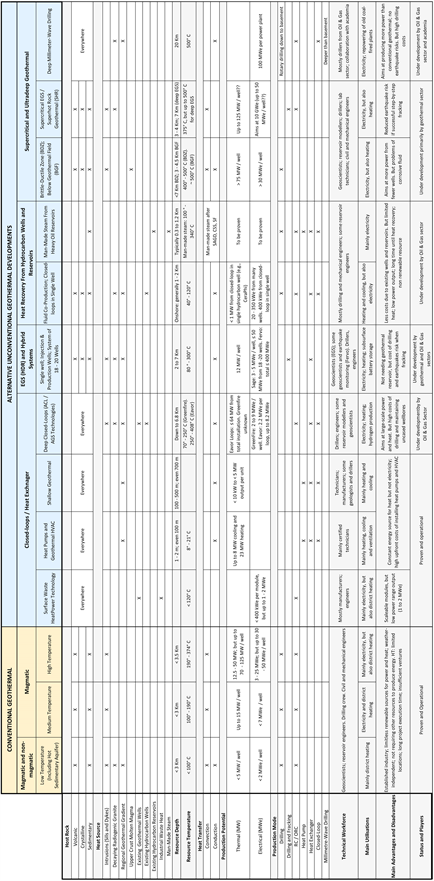
Unconventional geothermal alternatives have a wide range of heat (8˚C - 500˚C) and depths (1 m to 20 Km), but lack permeability or fluid. They require man-made stimulation to extract the heat by conduction mostly from the regional heat flow or decaying radiogenic granites. The near-surface geothermal HVAC exploits 8˚C to 25˚C at 1 - 2 m depth, with a capacity of <10 kW per unit, so does shallow geothermal but down to 500 m in wells with <5 MW heat capacity. Deeper unconventional approaches aim at higher temperatures and are advanced by two groups:
1) Geothermal developers are testing technologies down to 7 Km. They range from Enhanced Geothermal Systems (EGS) and hybrid systems to tap into 80˚C - 300˚C; to supercritical EGS, drilling below brittle-ductile transition zones, and under existing geothermal fields (convection) to capture up to 500˚C. Single well capacities are expected to be 12 MW and 3 to 5 MWe, but in a system of 18 - 20 wells that also offers battery storage, the capacity could be up to 50 MWe.
2) Most unconventional approaches are deep closed-loops, developed by the Oil & Gas industry in three main categories to generate primarily electricity but also heat. They are Advanced Geothermal Systems (ACL/AGS) down to 6.8 Km to capture up to 400˚C, with 2 - 9 MWe capacity per well. Secondly, the heat recovery from fluid co-production, from single hydrocarbon wells down to 2 Km - 2.5 Km (40˚C - 120˚C), or after drainage of oil reservoirs at <2 Km (100˚C - 300˚C), with ~400 kWe - 1 MWe capacity per well. Thirdly, the Superhot Rock Geothermal (SHR) to capture 500˚C from 7 Km - 15 Km, as well as the millimeter-wave drilling targeting also 500˚C but down to 20 Km depth and with a total capacity of 100 MWe to repower coal-fired plants.
Both shallow and deep unconventional geothermal approaches use closed-loops, heat exchanger or heat pump. However, EGS uses fractures as heat exchanger with risks of induced earthquakes during fracking. The workforce of all unconventional approaches deploys mostly drillers and engineers, but less geoscientists.
As a few takeaways, geothermal potentials are nowadays considered by geothermal developers, clean tech companies, and the Oil & Gas industry. Unconventional alternatives are to be developed everywhere, with HVAC and shallow geothermal already functional. The deeper unconventional alternatives targeting hotter resources are under developments and the Oil & Gas industry plays a prominent role with a transfer of technology, existing assets and tremendous finances. However, all these developments are still experimental and most are non-producing. Before becoming fully operational, they need to reduce the costs of drilling and technologies, adapt the Oil & Gas advanced technologies to higher temperature wells and power plants, minimalise the earthquake risks, gain experience and know-how similar to geothermal specialists. After succeeding, they could be deployed everywhere, with capacities similar to conventional geothermal resources, and together they will cover the global energy needs. Meanwhile, conventional geothermal resources are the proven source of clean energy, having an operational industry, producing non-stop energy regardless of weather, without requiring other forms of energy or ore to generate energy, and presenting high potentials for development. Therefore, they should receive comparable attention and investments for further developments, be it from the Oil & Gas industry or from other energy investment sources.
Acknowledgements
The authors thank the Energy Research Fund of National Power Company of Iceland (Landsvirkjun) for sponsoring this paper (Grant NÝR 2023). Many individuals brought their encouragement and support to this paper. We particularly thank Jóhann Fr. Kristjánsson for his critical computer assistance. We also wish to thank the anonymous reviewers for their helpful comments. At the Open Journal of Geology, we thank Joanna Cheng (Managing Editor) for her invaluable assistance during the publishing and typesetting processes.