1. Introduction
Solar energy is the conversion of energy from sunlight, either directly using pv cells or concentrated solar system. PV cells convert light into an electric current using photovoltaic effect. The earth receives 174,000 TW of incoming solar radiation at the upper atmosphere [1]. Approximately, 30% is reflected back to the space while the rest is absorbed by clouds and oceans. Nowadays, pv cells are getting popular day by day as the crude oil prices increases and unstable global market, furthermore with green peace movement, and the consciousness of mankind has heightened up regarding green energy, photovoltaic maybe one of the solutions for better as well cleaner energy as it is naturally harness from the Sun energy.
Recently, Takaki Kameya proposes a truly environmentally friendly light rail system using renewable energy. They have been conducting a joint research between Tokyo Technology University and Shonan Research Centre to provide traction energy from solar and wind power for light rail systems [2]. In the scope of PV train Project, 116 PV panels were attached to the curved surfaces of the coaches. Integration of solar energy and reduction of CO2 emissions were monitored for two-years observation period. PV panels with a total area of 3311 m2 and 325 kWp have been installed in roofing of the new Lehrter Bahnhof railway station in Berlin [3]. The largest solar railway station of the World was installed on Victorian-erab Blackfriars Bridge on London Thames River in England. 4400 PV panels were installed and produced 900,000 kWh/year [4]. Europe’s first solar train tunnel opened on the high-speed line between Antwerp and Amsterdam. The solar panels on the roof of Antwerp Central Station will also power to railway stations and trains using railway system. This project is expected to generate 3.3 MW of energy and reduce CO2 emissions by 2400 tons a year [5]. Solar panels more than 100 were installed five railway station by Regional Rail Link in Australia.
The demand of electric power is on rise and is anticipated to increase exponentially in future. The advantage of pv cell is enormous because it is environmentally pollution free. Several researchers have contributed many aspects of pv cells but no one considered how to utilize the PV cells over railway track. In this paper, we have analyzed, the performance of PV array as well as the equivalent circuit model. We also develop an algorithm flow chart for MPPT. A boost converter is required to step up this low DC voltage to the required DC link voltage. The conventional boost converters cannot offer such a high voltage gain. Even in case of extreme duty ratio, the conversion efficiency is declined due to losses. We have designed a model of boost converter using mosfet to increase its efficiency and losses. Finally, we have examined the feasibility of railway track for grid connected pv system.
The remainder of the paper is organized as follows. Section II introduces, the performance of pv, solar irradiation and MPPT as well as various performance metrics are also discussed. Simulation setup and analysis of the performance metrics are presented in Section III. Finally the conclusions are provided in Section IV
2. System Model
2.1. Pv Array
The set of photovoltaic modules is called photovoltaic or solar panel or an array. The photovoltaic modules that create an array can be connected to each other in series, parallel or Mixed, to obtain the voltage required by the system. This makes photovoltaic systems to be able to suit any installation, large or small. The type of power they provide is direct current (DC), so if we need alternating current (AC) or increase the voltage, it will have to be added an inverter or a power converter. For the installation of these panels it should be taken several considerations. First of all, it is to be noted that throughout the year, the angle of sunlight varies, and we must ensure that the direction of the light vector is parallel to normal vector of the panels. At the installation time, In addition, the panels must be installed with a minimum distance from any area of approximately 5 cm to permit an adequate airflow through the bottom, which prevents overheating that could reduce their performance. Another factor that might reduce its performance is dirt, since it makes difficult the incidence of sunlight.
2.2. Equivalent Circuit and Mathematical Model
An equivalent circuit refers to a theoretical circuit that retains all of the electrical characteristics of a given circuit. More complex circuits are often called macro models of the original circuit.
The equivalent circuit is shown in Figure 1 depicted.
where Rs is the array series resistance, Rp is the array parallel resistance, Ns and Np are the number of series and parallel modules respectively, I and V are the output current and voltage of the array and Im is the module current and can be obtained from the following equation:
[4]
where, a is the diode ideality constant, Vt is the thermal voltage of the array and can be obtained from the equation:
[5]
Ncs is the number of cells connected in series, q is the electron charge, k is Boltzmann’s constant and T is the temperature of the P-N junction in Kelvin’s. Ipv is the photovoltaic current and can be expressed by:
[6]
And Io is the reverse leakage current of the diode and can be calculated from:
where: Ipvn is the generated current at 25˚C and 1000 W/m2 (nominal conditions), Ki, Kv the current and voltage temperature confidents respectively, G is the irradiance and Gn is the irradiance at nominal conditions, Iscn, Vocn are the short circuit current and open circuit voltage respectively at nominal conditions and T is the difference between the actual and the nominal temperatures in Kelvin’s.
[7]
2.3. MPPT
Maximum power point trackers are a form of DC-DC converter. It uses electronic components to adjust PV outputs and make it operate at its maximum power point under changing irradiance and temperature. Interactive inverters often contain MPPT circuits. For large PV system with multiple PV arrays, individual MPPTs are designed to connect each array, in this way it is more efficient for MPPTs to operate at maximum output with each array that has different characteristics. So the total performance of PV system improves. Maximum power point of any PV varies with the variation of the atmospheric conditions (solar irradiance and temperature). This means that there is always one optimum terminal voltage for the PV array to operate at with each condition as shown in the Figuredepicted below to obtain the maximum power output. In our paper we applied the perturb & observe (P&O) method to extract that point (Figure2).
2.4. DC-DC Converter
The voltage we that have generated using the PV panel, in order to connect it to the Grid we have to increase the magnitude of the voltage, Which can be done with the use of a DC-DC converter, for our purpose we have chosen Boost converter which will help us to increase the level of voltage that we have generated (Figure 3).
2.5. Solar Irradiation
Irradiance is the amount of light energy from one thing hitting a square meter of another each second. Photons that carry this energy have wavelengths from energetic X-rays and gamma rays to visible light to the infrared and radio. We can estimate the total radiated power of the sun with the law of Stefan and Boltzmann.
where T is the temperature (about 5800 K), r is the radius of the sun (6.9 × 10⁸ m) and σ the Boltzmann constant (5.67 × 10⁻⁸ W/m2K4) and ε is the emissivity of the surface (Figure 4).
2.6. Solar Irradiation Model
In order to define the photovoltaic plant situation object of this thesis report, it is necessary to start showing the radiation that reaches the plant. Here, we work in rangpur district due to its geographical situation, the photovoltaic modules are oriented towards the south with 2 axis direction for maximum benefit of solar irradiation (Figure 5).
![]()
Figure 3. PSIM Model DC TO DC BOOST CONVERTER Using Mosfet.
By using this data we draw a virtual diagram for proposed area.

 Represents the railway line.
 Represents a typical tree beside the railway line.
• Represents the PV module mounted on the railway line.
For the PV system designed for Rangpur district, we have chosen for simulation is SAM (system Advisor Model) software. SAM has several built-in mathematical models for component such as photovoltaic module, inverter and other required tools. SAM gives various types of designing options such as residential, commercial, single owner etc. Using these options there are various kinds of system can be developed for desired PV plant. Firstly we have done some small design to gain primary knowledge and after that we designed a project of grid connected system. Here we have defined our location, orientation, and horizon. For location choosing, we have selected Rangpur in Bangladesh. Since we want to develop a PV system, so we have to choose a module and an inverter, defined our monthly energy consumption rates and declared our planned power. The parameters are given below.
3. Simulation Model
After simulation, the following results are found hereby.
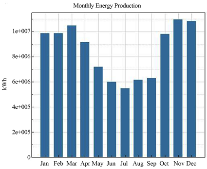
It shows that we could get less output on jun and july because that period will probably rainy season. Roughly, 11 - 14 hours will have possibility to fall rain. On November to march we will get our approximately maximum output because there will have no rain in that period of time.
After simulation, the implementation and another related cost shown by SAM software is given below.
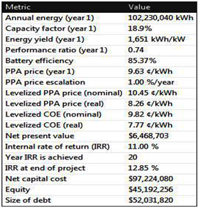
This result gives the general idea of annual energy in kwh and also shows the battery efficiency However, it shows us total net capital cost for 25 years. The proposed railway overhead PV power plant can produce 102,230,040 kWh energy annually. The net present value (NPV) will be around $6,468,703. The levelized cost of energy (LCOE) will also be around 7.77 cent/kWh. The project requires $90,243,200.00 for its final installation cost. The simulator System Advisor Model (SAM) shows the energy production data values for 25 years. The proposed project also required 242.3 acres land for its implementation.
4. Conclusion
In this paper, an environmentally friendly metro system using renewable energy is proposed. A suitable model is proposed for rangpur district in Bangladesh to improve energy consumption. The feasibility was studied with SAM software. SAM provides us total capital cost to implement this project. It also shows us how we construct this project in terms of practical implementation. Finally it gives us total estimated energy of rangpur pv power plant. Simulation results indicate that proposed PV system is suitable for rangpur. Furthermore, additional features could be added to improve overall efficiency. In future, we could use interior lightning system inside of the train by using solar energy. This project will promote the sustainability of policy makers to build more solar project and reduce CO2 from environment.