1. Introduction
Ambulatory parts of an insect consist of living and nonliving parts. Using these parts, insects can fly, crawl, walk or jump. Understanding the ambulation of insects is helpful in simulation of or building autonomous microsystem. The lifting force of this insect wing is about ten times that of an equivalent aircraft wing [1]. A damselfly is considered in this study because of its versatile features and its applicability for micro air vehicle (MAV). Damselfly wings are stiff and ultra lightweight that makes them to flap at very high frequency and maintain stability. Total mass of wings is 1% - 2% of mass of the insect. Thus, a study of the insect wings helps to advance existing flying systems including materials and structural concepts.
Biological branch and species name of the North Carolina (NC) damselfly (see Figure 1(a)) are Odonata and Lestes sp, respectively, as stated by Combes and Daniel [2]. Figure 1(a) shows four wings of the fly and Figure 1(b) shows a microscopic detail of a typical wing. The wing length (distance between proximal end and distal end) varied from 20 to 25 mm and the cord length (distance between leading edge and trailing edge) varied from 5 to 6 mm. The wing is composed mainly of veins (stiff member) and membrane (filler material). The major veins of the wing are Costa, Subcosta, Radius and other minor veins (see Figure 1(b)). Nodus and petrostigma/ stigma are two distinctive features of the wings. The nodus lies in the leading edge of the wing and Subcosta ends on nodus. The petrostigma, like a fuscous mark, is situated near the tip. The nodus and the petrostigma improve the flexibility of wing and prevent fatigue fracture [3]. The petrostigma performs balancing of the mass, stabilizes flight at high speed and eliminates any airflow vibrations. If the petrostigma is cut off the dragonfly could still fly but the flight becomes unstable [4]. The basic material of the insect vein is made of chitin, a long chain polymer of N-acetyl-glucosamine that is similar to cellulose or keratin materials [5]. The flying behavior of insects is strongly related to the physical properties of wing [1,6-8]. If the wing structural features and the material properties are known then one could fabricate a synthetic wing by the right choice of commercial materials. Furthermore, the wings flying response is directly related to its material and structural properties.
Quantitative measurements of the mechanical properties of insect wing, namely, the vein and membrane are useful in development of bio-mimetic system suitable for MAVs. Different wing zones bear different loads, and their mechanical properties are different because of adaptation [9]. Newman and Wooton [5] were the first to measure gross flexural stiffness of dragonfly wing from a simple cantilever beam test. Combes and Daniel [2] and later Wood et al. [10] measured flexural stiffness of the wing by applying a point force at 70% of wing span. Wang et al. [11] measured the gross flexural modulus of the wing by three-point bend test. These tests provide only the gross flexural stiffness of the wing not the material properties of the veins.
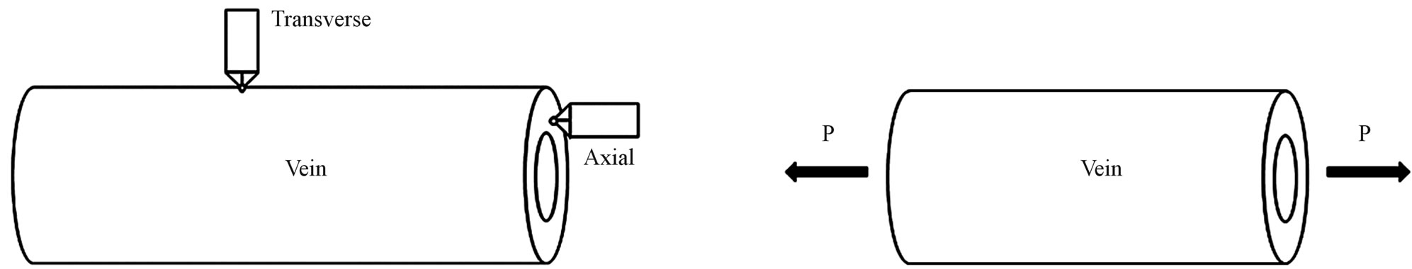
Kempf [12] and Kreuz et al. [8] conducted the transverse indentation test (see Figure 2(a)) on the veins and measured the indentation modulus that varied between 2.8 and 2.9 GPa. These moduli values are of the same order as the commercial epoxies (3.0 - 3.5 GPa). However, they did not report specifically what type of veins was tested. Chang et al. [6] performed transverse indentation test on Costa, Subcosta and Radius (referred to as longitudinal vein) and reported the elastic modulus to be about 30.11 ± 4.63 GPa. Sun et al. [1] performed similar nanoindentation test on Costa, Postal and Radius veins and reported that the indentation modulus varied from 0.2 to 3.8 GPa for Costa and Radius while it is 0.01 to 1.2 GPa for Postal veins. Talucdher et al. [13] performed an axial indentation test (see Figure 2(a)) of Costa, Subcosta and Radius veins of damselfly wing (in Reference [13], damselfly is wrongly referred to as dragonfly) and found the indentation modulus varied between 11 - 16 GPa and these values are different from the transverse indentation modulus reported by other researchers. A summary of indentation modulus of dragonfly/damselfly wing veins reported in the literature listed in Table 1.
These large variations in moduli reported in the literature for insect veins show that further exploration of properties of veins is needed to establish more reliable values. In addition, transverse indentation of a curved surface is difficult to test. Unless the surface curvature correction is applied [14], the computed results could be incorrect. Therefore an alternative approach of direct testing of veins is chosen in this paper. The objective of this paper is to conduct microtension test of veins, measure tensile strength and modulus and compare them with the data in the literature. In addition, the effect of freshness of specimens on the tensile properties of veins is investigated.
2. Tension Test
2.1. Test Specimen Preparation
As shown in Figure 1(a), the damselfly has four wings, namely, left front (LF), left hind (LH), right front (RF) and right hind (RH). These wings were dissected from body (cuticle) of the fly. Longitudinal straight portion of the Costa (the leading edge of the vein) and Radius (parallel and behind to Costa) veins were selected (see broken lines in Figure 1(b)) and lengths ranged from 10 to 15 mm sliced with the surgical knife. A minimum length of the specimen is 10 mm, with the gauge length (Lg) of 6 mm and 2 mm at both ends for attachment. The transverse membrane edges were trimmed using a surgical knife. The specimen is a cylindrical rod and ends are attached to a paper tab. Unsupported (gauge) length of the specimen is measured by an optical microscope; the image is shown in Figure 3(a).
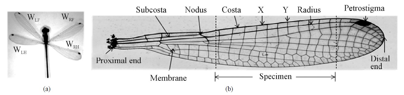
Figure 1. NC Damselfly (a) and details of a sample wing (b).
 (a) (b)
Figure 2. Nanoindentation and microtension test. (a) ndentation test; (b) ension test.
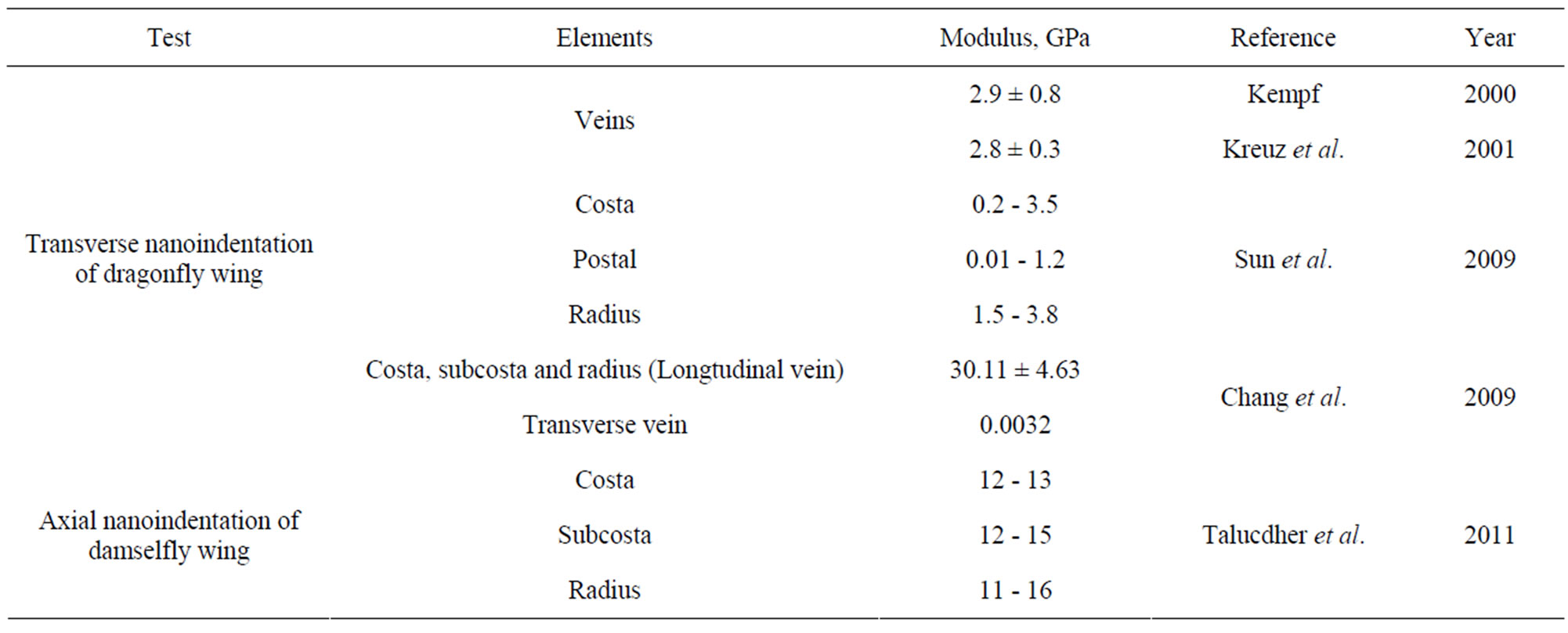
Table 1. Properties of dragonfly/damselfly wing veins from literature.
 (a) (b) (c)
Figure 3. Specimen Preparation (a) Micrograph of a test specimen (b) Specimen mounting paper frame (c) Specimen mounting in a paper frame.
Membrane attachment seen as fuzzy material in Figure 3(a) is small and its effect is neglected. The tension test of the vein was conducted using a specially made paper frame to hold the specimen in tension grips. A white paper test frame (38 mm × 25 mm) with an opening of (6 mm × 12 mm) was made with two halves top and bottom (see Figure 3(b)). The specimen (vein) ends were held at the bottom-half of the frame by using gorilla glue and double sided adhesive tape. The vein was aligned along the center line of the frame. The top half of the frame folded down along the dotted line. The twohalves of the frame with specimen were pressed so that all three were bonded. The specimen preparation was delicate; a special care was required. After one hour of cure, the specimens were imaged at 50X magnification by Zeiss Axio Imager M2m. Using extended depth technique, focusing image at every pixel with full background correction, stitching procedure and x - y mapping an expanded view of the specimen was developed. The Figure 3(a) shows one such image. Using Image pro 6.0, the gauge length (Lg) was accurately measured and recorded. Two types of vein samples were tested; fresh and dry. Fresh samples were extracted from damselflies immediately (within 1 - 2 days) after they were caught. The dry sample veins were the samples extracted from wings and stored in a desiccator for 1 year before the test. No other scientific procedure was used for distinguishing the two sets of samples. Figure 3(c) shows the specimen, frame and loading of the vein sample.
Veins from two flies (fly #01 and fly #02) were tested. Figure 4 shows the test plan for fly #01, similar plan was used for fly #02. The specimen is represented by vein
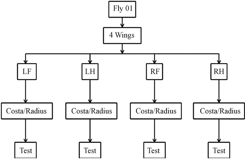
Figure 4. Flow chart of specimen selection and test.
name-wing identification—fly #. The vein name is Costa/Radius, wing identification is LF, LH, RF or RH and the fly # is 01 or 02. The first column in Tables 2 and 3 lists all the samples tested. The dry samples are denoted with the letter “D”. Wing identification was not used for dry samples, as it was not recorded when severed.
2.2. Testing
The test vein specimens were 45 - 70 µm in diameter (D), 10 - 15 mm in length (L) and 6 mm in gauge length (Lg). Average Lg/D ratio was 108, which is large enough for the specimen to perform like a string. Shimadzu AGS-X tensile test machine with 50 N load cell and resolution of
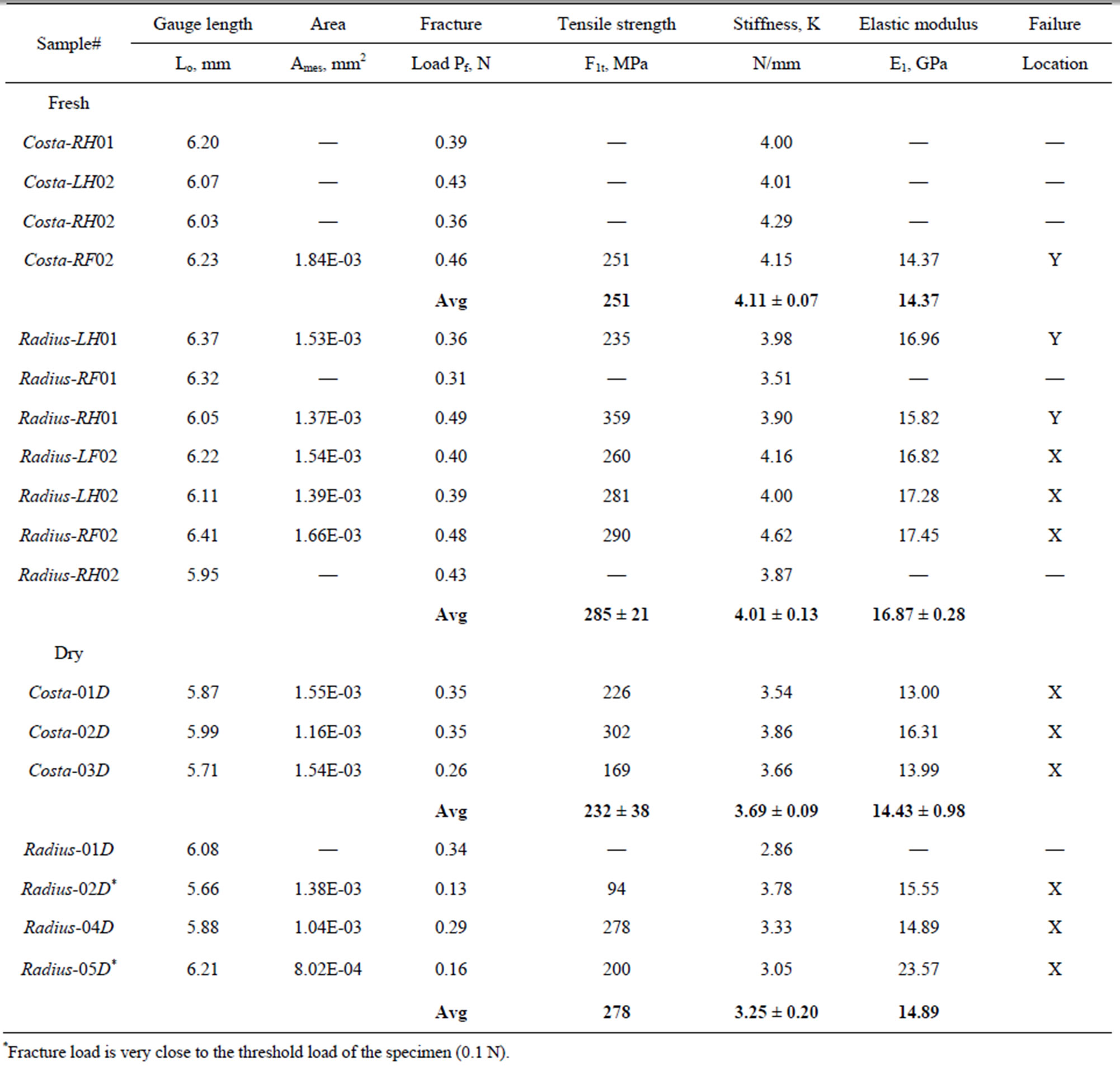
Table 2. Tensile strength and modulus of costa and Radius of damselfly wing.

Table 3. Cross-section area of veins of damselfly wing.
0.1 N ± 1% error was used for testing. Stroke control loading at a displacement rate of 0.1 mm/min was applied. The manufacturer supplied TrapeziumX software was used for data acquisition and post processing the results. The machine displacement was compared with direct measurement of displacement using a traveling microscope for a nylon fiber of 6 mm gauge length and found that the difference between the two was less than 2%. Therefore the machine (stroke) displacement was used to measure displacement in all tests. The specimen with the paper frame (see Figure 3(c)) was placed between the grips of the tensile test machine. The specimens were aligned such that the load axis is parallel to the axis of specimen. The out of alignment may cause specimen bending and premature failure of the specimen.
Any slackness in the specimen was adjusted before the test was continued. The specimen was loaded to about 0.025 N, then the two arms of the paper frame were cut by a scissor and the test was continued till the failure. Figure 5 shows the close up view of the test specimen in the test machine. 
The load and displacement were recorded continuously till the specimen failed. The ultimate failure loads of all specimens tested are listed in Table 2. The ultimate loads varied from 0.13 N to 0.49 N where as the machine threshold (recommended minimum) load is 0.1 N. Failure load that is near 0.1 N is considered to be inaccurate and ignored in average calculation. The displacement at failure varied from 0.1 mm to 0.14 mm except for
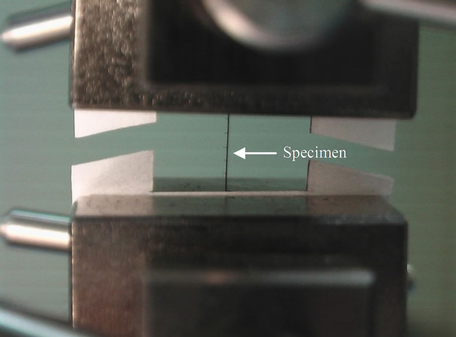
Figure 5. Photograph of specimen in tension test frame.
specimens Radius-02D (0.04 mm) and Radius-05D (0.07 mm). These two sets of data were considered to be outlier and are not included in the average calculation. Many specimens were broken prematurely and they were discarded.
3. Results and Discussion
3.1. Load-Displacement Response
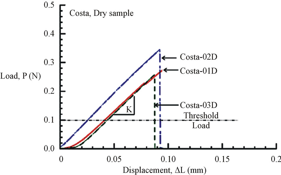
Figures 6(a) and (b) show the tensile load-displacement responses of fresh Costa and Radius samples, respectively. Figures 7(a) and (b) show the tensile load-displacement responses of dry Costa and Radius samples.
 (a)
(a)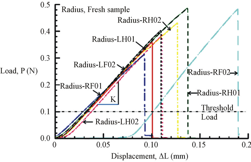 (b)
(b)
Figure 6. (a) Load-displacement response of fresh Costa samples. (b) Load-displacement response of fresh Radius samples.
All load-displacement responses are linear up to failure and the fracture was sudden, a representative of brittle fracture. From the linear portion of the load-displacement plot, the stiffness (K) of the specimen was calculated from a linear regression analysis. The elastic modulus of the vein is calculated from the Equation (1):
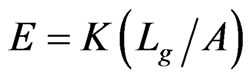 (1)
(1)
where, the stiffness (K) is the linear slope of the loaddisplacement curve, Lg is the specimen gauge length, and A is the cross-sectional area, which has to be determined from the specimen cross-sectional area at the fractured section. The fracture load (Pf) and the measured value of K for all specimen tested are listed in Table 2. The average stiffness K is 4.11 ± 0.07 and 4.01 ± 0.13 for fresh Costa and Radius, respectively. Whereas, the average K is 3.69 ± 0.09 and 3.25 ± 0.20 for dry Costa and Radius, respectively. The tensile strength (σt) of the specimen is calculated from the fracture load (Pf) and the cross section area A using the Equation (2).
 (2)
(2)
 (a)
(a)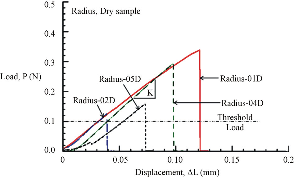 (b)
(b)
Figure 7. (a) Load-displacement response of dry Costa samples. (b) Load-displacement response of dry Radius samples.
3.2. Fracture Morphology and Cross-Sectional Area Measurement
The fracture morphology of the broken specimens were imaged by Hitachi SU8000-I Field Emission Scanning Electron Microscope (FE-SEM). The fracture surfaces of the specimen were coated prior to imaging with Au-Pd by Polaron E5400 sputter coater to minimize surface charging effects. As shown in Figure 8, the fracture surfaces are mostly flat. Some specimens fractured between the cross veins (primary fracture at “X” in Figure 1(b)) and the other is at the junction of cross veins (at “Y” in Figure 1(b)). The fracture surfaces at X and Y are shown in Figures 8 and 9, respectively. Fracture surfaces of these two sections are different and accordingly a variation in fracture load or the strength is expected.
3.3. Cross-Sectional Area Approximation
Scanning Electron Microscope (SEM) images of fracture surfaces were used to measure the cross-sectional area of the specimens. Inner and outer boundaries of vein crosssection were traced and areas were directly calculated using Image pro 6.0 (see Figures 8(a) and (c)) and are listed in Table 3 as the measured area. An alternative
 (a)
(a)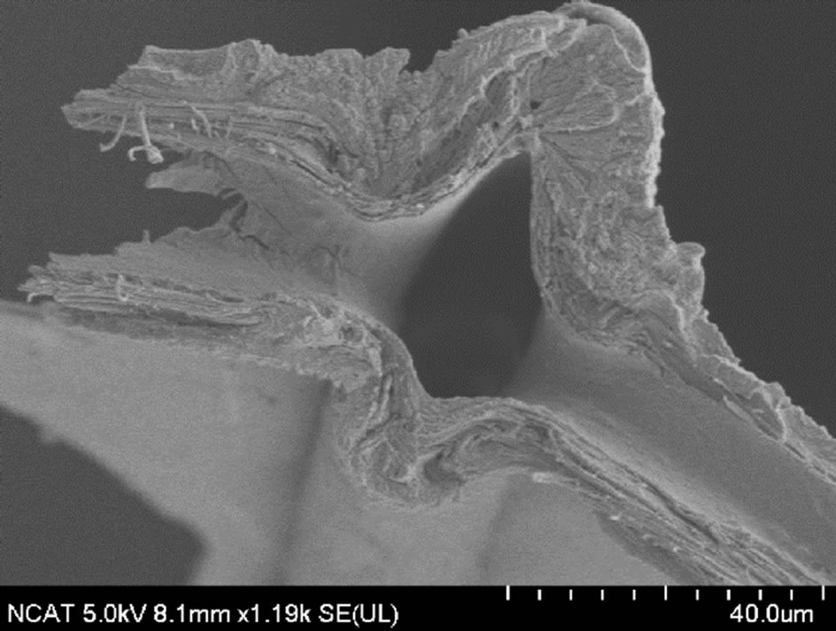 (b)
(b)
Figure 9. Fracture surfaces of selected specimens at section “Y” of Figure 1(b). (a) Costa RF02; (b) Radius LH01.
approach was used was proposed by Talucdheer et al. [13], an elliptic representation (see Figure 10) was also used to estimate the cross-sectional area. The cross-section is represented by a two ellipses; inner and outer. The
 (a)
(a) (b)
(b)
Figure 10. Elliptic approximation of vein cross-section. (a) Sample fluorescence image of cross-section of Costa; (b) Idealized Cross-section of a vein of damselfly wing.
outer major and minor axes were 2A and 2B, respectively. Similarly 2a and 2b were represented the inner major and minor axes, respectively. Lengths of the axes were measured by using Image pro 6.0 and are listed in Table 3. The elliptic cross-section area is calculated by the Equation (3).
 (3)
(3)
The Calculated areas are also listed in Table 3. The difference between measured and calculated areas is expressed as a percent difference in the last column of Table 3. The maximum difference is 13% and in most cases it is less than 10%. As stated previously, some specimens broke into several pieces and they were not recovered, those data are not listed in Table 3. The cross-section area ranged from 1000 to 1700 sq µm for Radius and about 1200 to 1800 sq µm for Costa. The dry sample had slightly smaller cross-sectional area than the fresh samples. The measured cross-sectional area of the specimen is used to calculate the tensile strength (from fracture load, Pf) and modulus (from stiffness, K that was measured previously).
3.4. Tensile Strength and Modulus of Veins
The calculated tensile strength and modulus for Costa and Radius specimens for both fresh and dry samples are listed in Table 2. As explained previously some specimens broken were not recovered, therefore the crosssectional area of the specimens could not be measured and the strength and modulus are not reported. The average strength and modulus of fresh Costa is 251 MPa and 14.37 GPa, respectively, and for dry Costa they are 232 ± 38 MPa and 14.43 ± 0.98 GPa, respectively. Properties of both fresh and dry samples of Costa are nearly same, within one standard deviation. The average strength and modulus of fresh Radius is 285 ± 21 MPa and 16.87 ± 0.28 GPa, respectively, and for dry samples they are 278 MPa and 14.89 GPa, respectively. Note the Radius-04D and Radius-05D data are not included in the average because the failure load is very close to the threshold limit of the test machine. The last column in Table 2 includes the location of fracture, namely X (primary location) or Y (secondary location). The strength at cross-over veins is generally lower except for specimen Radius-RH01. In general the tensile properties of fresh and dry samples are nearly same, which agrees with Song et al. [7] observation for wing membranes of the living and the dead dragonflies.
Table 4 summarizes the average tensile and modulus of Costa and Radius veins and also the axial indentation modulus [13]. The tensile modulus of veins is about 8% - 10% higher than the indentation modulus. Interestingly, the tensile modulus of damselfly wing veins (14 to 17 GPa) nearly matches that of human bones (10.4 to 13.6 GPa) as reported by Rho et al. [15]. Also noted that the commercial polymers like epoxy has a modulus of about 3.5 GPa, which is much lower than the biological bones and veins. Therefore the commercial resins matrix has to be stiffened by fillers to achieve the matched properties.
4. Conclusion
Longitudinal veins namely, costa and radius extracted from four wings of NC damselfly were tested in a microtension test machine. A special paper frame was made to hold mm size specimen. The specimens were classified into fresh and dry; fresh samples were the specimens

Table 4. Summary of tensile strength and modulus from microtension test and compressive nanoindentation test.
prepared immediately after extracting from the fly and dry samples were the specimens dried in desiccators for 1 year and later tested. Field Emission Scanning Electron Microscope was used to measure the fracture morphology of the vein. The results showed that the veins were brittle and fracture surfaces were flat. The average tensile strength and modulus of fresh Costa are 251 MPa and 14.37 GPa, respectively, and for dry Costa the strength and modulus are 232 ± 38 MPa and 14.43 ± 0.98 GPa, respectively. Properties of both fresh and dry samples of Costa are nearly the same. Thus the aging of damselfly veins in a desiccator had no impact on its tensile properties. The average tensile strength and modulus of fresh Radius are 285 ± 21 MPa and 16.87 ± 0.28 GPa, respectively, and for dry Radius are about 278 MPa and 14.89 GPa, respectively. The tensile modulus of veins is about 8% - 10% more than the axial indentation (compression) modulus reported in the literature. Furthermore, tensile modulus of damselfly veins is nearly the same as that of human bones.
5. Acknowledgements
The authors would like to acknowledge the financial support of Army Research Laboratory (ARL) through Micro Autonomous Systems and Technology grant number W911NF-08-2-004.
NOTES