Tooth Surface Design for Variable Transmission Ratio Bevel Gearing ()
1. Introduction
Bevel gearings are used in the situation of driving between the unparallel axes and have a wide application field. Because the gearing motion is so complex, the mathematical theory is very deep and the calculations are multifarious [1] . In this paper, an apparent and effective method is proposed, although it doesn’t need unfathomable mathematical theory.
At first, based on the gearing feature, a pair of pitch curves (from gear 1 and 2) are generated. Tooth profile 1 can be arbitrarily drawn around the pitch curve 1; tooth profile 2 is uniquely formed by the motion of the tooth profile 1 along the pitch curve 2. The motion of the tooth profile 1 divides the space into two regions (scanned by gear 1 and not scanned by gear 1) and their boundary line. The region not scanned by gear 1 can be the region where gear 2 exists; otherwise the tooth profile 2 should be the boundary line. The boundary line could be extracted by digital image processing [2] and translated into a real dimension finally. The gear 2 is obtained just like the paper-cut, so the complex process of enveloping line solution of mathematical meaning could be avoided.
2. The Presentation of the Problem
The aim gears to be design are a pair of bevel gearings whose axes are vertical to each other as shown in Figure 1.
The transmission ratio:
 (1)
(1)
where: ;
;
i is the transmission ratio;
 are teeth number;
c is adjusting constant;
 are the rotation angle of gear 1 and 2.
The mathematical relationship between t1 and  is shown in Figure 2.
![]()
Figure 1. The position relationship of the pair of bevel gearing, where γ is the angle between the two gear’s axes, and .
.
![]()
Figure 2. The relationship between t1 and t2 according to Equation (1), where  is the integration of Equation (1).
3. The Solution of the Two Pitch Curves
The pitch curves are two fictitious closed curves on the two gears which have pure rolling behavior. Suppose that gear 2 (the axis is OY) lives in coordinate system {O} and don’t move, on the other hand, gear 1 lives in coordinate system {A}, and its rotating axis is OA. OA contrarotates based on OZ axis in XOY plane (see from  to
to ), while gear 1 contrarotates based on OA (see from A to O), as shown in Figure 3.
The {O} coordinate of a point K on the pitch curve in {A} is {x, y, z}. After gearing  and
and  angle, K moves to K' whose {O} coordinate is {x', y', z'}. So:
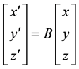 (2)
(2)
where:
 (3)
(3)
 ,
, ![]() are the small rotating steps of axis OA and gear 1.
are the small rotating steps of axis OA and gear 1.
According to the meanings of pitch curve:
![]() (4)
(4)
According to Equation (2):
![]() (5)
(5)
![]()
Figure 3. The two coordinate systems of the two gears. Gear
2 in
coordinate system {O} and gear
1 in
coordinate system {A} ![]() because of
because of![]() .
.
where:
![]()
Because:
![]() (6)
(6)
So, the equations have infinite solutions:
![]() (7)
(7)
when![]() :
:
![]() (8)
(8)
where transmission ratio ![]()
The intersecting line G2 between the bevel surface of Equation (8) and spherical surface
![]() (8’)
(8’)
is the pitch curve of gear
2 in
{O}. The equations of the intersecting line G2 are:
![]() (9)
(9)
The equations of the pitch curve G1 of gear
1 in
{A} can be also obtained:
![]() (10)
(10)
The pitch curves G1 and G2 is shown in Figure 4.
![]()
Figure 4. The two pitch curves G1 and G2.
4. The Design of the Tooth Profiles
4.1. The Generation of Gears
When the transmission ratio is given, the two pitch curves are determined uniquely. However, the tooth profile curves of the two gears are not unique. When one is given, the other is determined. We can design a three- dimension curve based on G
1’
s pitch curve to be its tooth profile curve:
![]() (11)
(11)
where:![]() , H is adjusting coefficient,
, H is adjusting coefficient,![]() come from Equation (10).
come from Equation (10).
So, G
1’
s tooth profile curve S1 is shown in Figure 5.
Suppose that on the spherical surface, the S1 rolls purely along the pitch curve G2 (G1 and G2 are tangent), then the region where S1 doesn’t sweep should be the region where gear 2 exist. The black region where is swept by S1 (see from ![]() to
to![]() ) is shown in Figure 6, and the new pitch curve of gear 2 (S2) appears.
) is shown in Figure 6, and the new pitch curve of gear 2 (S2) appears.
4.2. The Extraction of Tooth Profile Curve
The black region (in Figure 6) swept by S1 is projected on XOY plane, as shown in Figure 7. The tooth profile curve S2 can be obtained by image processing technology. As shown in Figure 7, the color region is composed by civil points and the white region is composed by outside points. The boundary line between the color region and white region can be found and extracted orderly in a given direction by image processing.
OA and OB are calibration lines to translate pixel size into real size; the color region is composed by civil points and the white region is composed by outside points.
We provide (this provision really makes sense) that these points are boundary points: if there is at least an “outside point” on the position “a, c, e, g” of point M as shown in Figure 8, then the point M is boundary point. So, there are three types of points: outside point “0”, civil point “1”, boundary point “
2”
. We can find a boundary point “
2”
as a beginning point along any scan line, and name its address “P
1”
. Search all the eight positions
![]()
Figure 5. G
1’
s tooth profile curve S1.
![]()
Figure 7. Inner points and outer points.
![]()
Figure 8. The eight positions (a, b, c, ∙∙∙, h) of point M.
(a, b, c, d, e, f, g, h) of P1 (see in Figure 8), name the first boundary point’s address “P2”, and let the content of P1 be “
3”
which won’t be searched anymore. P1 replaces P2, and find the next P
2 in
the same way till return to the beginning point. Therefore, at last, all the boundary points are “
3”
. This process is called ordinal extraction, as shown in Figure 9.
The flow of the ordinal extraction of boundary line is shown in Figure 10.
4.3. The Translation of Pixel Size into Real Size
The tooth profile S2 which has been extracted is shown in Figure 11(a). But S2 is pixel meaning, so it should be translated into real size. The relationship between pixel size and real size is shown in Equation (12).
![]() (12)
(12)
where xp, yp are pixel coordinate; x, y are real coordinate; ![]() are the length of the lines which we know;
are the length of the lines which we know;![]() ,
, ![]() are the pixel number in OA and OB. S
2 in
a real coordinate is shown in Figure 11(b). The XOY projections of the four positions of S1 gearing with S2 are shown in Figure 12.
are the pixel number in OA and OB. S
2 in
a real coordinate is shown in Figure 11(b). The XOY projections of the four positions of S1 gearing with S2 are shown in Figure 12.
4.4. Discussion
Will the two gears run steadily? Will their profile curves leave each other? These are not in the scope of this paper
![]()
![]()
Figure 9. The ordinal extraction of boundary line.
![]()
Figure 10. The flow of ordinal extraction of boundary line.
![]() (a) (b)
(a) (b)
Figure 11. (a) The extraction of S2 and (b) S
2 in
a real coordinate.
(which could be known from [3] -[6] ). But a geometrical answer can be given. At an ecumenical position of gearing, via a tangent point of two tooth profile curve, draw a normal line of a tooth profile curve. The directions of the normal line and the press force at this point are same. If there are some normal lines upon the rotating axis and some normal line below the rotating axis, that is to say, the moments of the press forces of the rotating axis are complete negatively and positively, and then the gearing is steady reasonably.
For example, as shown in Figure 13, draw three normal lines of gear 2 via the tangent points, the moments of press force F1, F2 are clockwise and moment of F3 is counterclockwise. But this is only a geometrical precondition to be steady; the detailed mechanical analyzation is not in the scope of this paper.
4.5. Three-Dimension Situation
In the three-dimension situation, S2 is a space curve on the spherical surface (the “S
2”
mentioned before is its projection on XOY). Given a radius “a” (from Equation (8’)), there will be a pair of gears S1 and S2, as shown in Figure 14. Therefore, the part of the spherical surface encircled by S1 or S2 is a cut section of a bevel gearing corresponding radius “a”. All the cut sections corresponding different radius “a” compose the whole bevel gearing.
![]()
Figure 13. The normal lines via the tangent points.
![]()
Figure 14. The cut sections of the two bevel gearings on the spherical surface.
5. Conclusion
In this paper, a novel design method of space bevel gearing based on gearing feature is proposed. The two pitch curves are generated based on the transmission ratio, and then a tooth profile could be designed based on its pitch curve independently. According to its motion, the second tooth profile could be found and translated into a real size by image processing technology. Comparing to complicated method [7] -[11] , this method could avoid complex calculation and exceptional solution, and could almost design any gear or rack. However, this method is also limited in precision, if the image is very small, the size error will arise due to lack of pixels [12] . So, the image must be zoomed in enough.
Acknowledgements
This work was supported by China Post-Doctoral Foundation No. 2012M520572, Tianjin Municipal Education Commission Grant No. 20120401, and Tianjin Municipal Science and Technology Commission Key Grant No. 14JCZDJC39500.
NOTES
*Corresponding author.