The Flight of Albatross—How to Transform It into Aerodynamic Engineering? ()
1. Introduction
Our present wind and water turbines are technically conceived to respond to a quite homogeneous streaming pattern. If the flow of air or water would be inhomogeneous, the resulting forces on airfoils or turbines would be inhomogeneous, resulting in non-ideal technical performance. In natural environments, however, inhomogeneous streaming patterns are quite common. But our present aeroand hydro-mechanic technology has not yet developed strategies to exploit them efficiently. That this should be possible is convincingly demonstrated by a natural example: the seemingly effort-less flight of the albatross over the sea, where air up-drifts are essentially lacking. The flight manoeuvres of the albatross (Figure 1) have for a long time stimulated imagination of scientists and engineers.
How is it possible to fly seemingly effortless without flapping wings over a sea surface which does not provide wind up-drifts [1] -[3] . It has been known for a long time that the albatross is taking advantage of mechanisms which also give rise to the Magnus effect, the same phenomenon which is giving a spinning tennis ball a characteristic deviation in its flight path [4] . The physics behind the albatross’ flight has well been analysed [5] and explains the power source for the up-drift force as the product between relative wind velocity V and the wind velocity gradient u' above the sea surface (vertical component z) according to the relation Figure 2:
 (1)
(1)
By entering the wind gradient the effect of a marked increase in airspeed appears which implies an increase in kinetic energy. The acceleration (dV/dt) results as product of the wind speed profile du/dz and the vertical airspeed component Vsin(γ) which is the amount of increasing airspeed due to the finite wind step velocity, also known as climb rate (dz/dt).
When the albatross heads for an inclined path into the wind profile then he is able to accelerate in this direction (acceleration = a). Such forward force depends, of course, on the albatross mass m (which can reach 10 kg) times the airspeed V derived with respect to the time. The forward impulse is correlated with the airspeed V (relative wind velocity registered by the flying bird),

Figure 1. The Southern Royal Albatross (Diomedea epomophora) developed a highly specialized flight behaviour. He spends 95% of his life at sea. While circumnavigating the Antarctic continent on his wings, which exceed 3 m in width and are rarely used for flapping, he may travel 300 - 800 kilometres a day in an environment without air up-drifts (photos: H. Tributsch).

Figure 2. The wind velocity gradient above sea level is shown (left) together with vectorial diagrams describing the flight behaviour of the albatross (center and right). The up-drift correlates with the wind profile (adapted from [6] ).
 (2)
(2)
The pitching angle (γ) and the heading angle (ψ) depicted in Figure 2 determine the inclination of the albatross flight upwind and affect the magnitude and direction of the forward up-drift impulse,
 (3)
(3)
Understanding now the physical basis of the force which the albatross is exploiting we have to turn to the complicated task of constructing a wind machine, able to extract energy from inhomogeneous air streams.
2. Technical Challenges and the Results
A biomimetic strategy aims at extracting technical information from biological systems to achieve as simple as possible a model of relevant properties. A biological system tends to solve different problems simultaneously [7] . Technology, in contrast, aims at well specialized technical solution. The most straight-forward strategy with respect to an understanding of the basic requirements for energy gain based on the albatross flight technology would be to look first at the most simple flight pattern used by the albatross Figure 3.
When the albatross, after taking advantage of the special up-drift force which is activated, reaches the highest point of the periodical flight patterns, he can fly down into any direction while converting potential energy into kinetic energy and while harvesting additional energy from the wind gradient.
However, while conserving a reasonably flight velocity with respect to the wind, he has then to turn against the direction of the wind gradient. This way he maximizes the product of relative wind velocity and wind velocity gradient according to Equation (1). Now the up-drift force becomes active again and the albatross convert his kinetic energy into potential energy by gaining approximately 15 - 20 meters height. From here the albatross can again reorient the flight direction while taking advantage from the gain in potential energy and from the down-wind conditions.
With respect to the most simple flight manoeuvre-prototype for technology the following approach would appear to be the most promising 1) the simplest albatross flight pattern should be taken as a first model 2) a rotational movement should be achieved instead of a translational one 3) the power gain should be extracted

Figure 3. Albatross flight manoeuvres of dynamic soaring into any overall direction. (a) cross-wind snake manoeuvre (b) upwind snake manoeuvre (c) circumnavigation manoeuvre (d) snaking hover manoeuvre. The flight patterns are indicated, besides of the wind gradients, with which the albatross is interacting.
periodically in the wind gradient during the rotating movement. Both, the gained potential energy and the extracted energy from the downwind may contribute. In terms of biomimetics engineering this corresponds to the simplest abstraction of the biological engineering example. However, more details have to be learned about the albatross and his flight.
2.1. How Did Evolution Approach the Technical Problems of Albatross Flight?
It is well known that in ordinary flight technology via airfoil the velocity difference of air between the upper more curved foil surface and the lower less curved surface is a critical factor in producing (upward) lift [8] . The difference in air pressure generated is giving rise to the responsible force. Above a sea surface an air velocity gradient is already present and this is what the albatross is exploiting. Consequently, a much less curved wing profile compared to those of other large birds [9] should be expected for the albatross. This is actually observed as Figure 4 shows for a member of the albatross family.
With such an only moderately bent wing profile the albatross extracts energy from the streaming air by engaging in its characteristic flight pattern. Additional to the four flight patterns (Figure 3) which were illustrated before, the simplest one is shown in Figure 5.
As Figure 5 visualizes the albatross starts by entering the air velocity gradient with a sufficiently high relative wind velocity close to the ocean surface (A). He enters the air velocity gradient with a velocity of maybe 25 m/s

Figure 4. Wing profile characteristics of different birds (adapted from [8] ). The albatross travels with the least curved wing profile. It explains its clumsiness during take-off and during flapping flight, but is a key to dynamic soaring.

Figure 5. Scheme of most basic circular dynamic soaring trajectory of the albatross. Shown are different projections of the flight manoeuvres (top right: seen from above; top bottom: seen parallel to the sea surface).
and rises to a height of approximately 20 meters while reducing its speed (B-C). With the potential energy gained the albatross flies a loop downwards (D-E) and again turns into the wind gradient near to the wave crests to repeat the cycle. By converting potential energy and gaining additional energy from the downwind he increases again the kinetic energy for entering the wind velocity gradient (E). During the albatross flight the final position (E) is separated from the starting point (A) by a certain distance since the albatross migrates in the search of food.
As explained in Figure 6, a technical realization on this manoeuvre could function more or less identical, representing however a circular albatross manoeuvre without the need for local displacement. The consequence would be a circular manoeuvre during which periodically gained potential energy as well as downwind energy is changed into kinetic energy. The kinetic energy is needed for generating the up-drift and in a technical system would be the source of energy gain out of the velocity gradient. Figure 6 also explains, how in a rotational wind energy harvesting system foiland wind velocities add in different positions within the wind velocity gradient. The depicted manoeuvre appears to be the manoeuvre closest to the albatross example. But technically it is not the only possible one and the engineering options should therefore be further analysed.
2.2. Technical Realization of the Albatross Flight Model
As in part outlined in a master thesis [10] in some detail basically three different strategies are imaginable for a technical approach 1) a linear system 2) a rotational system and 3) an intermediate system with respect to the path of the airfoil. In all these cases energy gain from the wind gradient appears to be possible but the boundary conditions are somewhat different, as depicted in Figure 7.
During the flight of the albatross the up-drift is proportional to the relative wind velocity V. This relative wind velocity adds the velocity of the air (wind) and the velocity of the albatross when flying into the wind gradient. In a technical system the albatross will be replaced by an artificial airfoil. This airfoil develops different velocity in different technical set ups.
A foil which is periodically moving up and down (case a) in the wind velocity gradient contributes zero velocity to the relative wind velocity V (= Vwind + Vfoil). For a technical system where a foil is rotating into the wind the foil velocity is periodically changing in dependence of the position within the wind gradient. In case b the relative wind velocity will be the sum of the wind velocity plus a varying foil velocity. In case c two linear movements are superposed to yield a more complex foil trajectory with a corresponding more complex foil
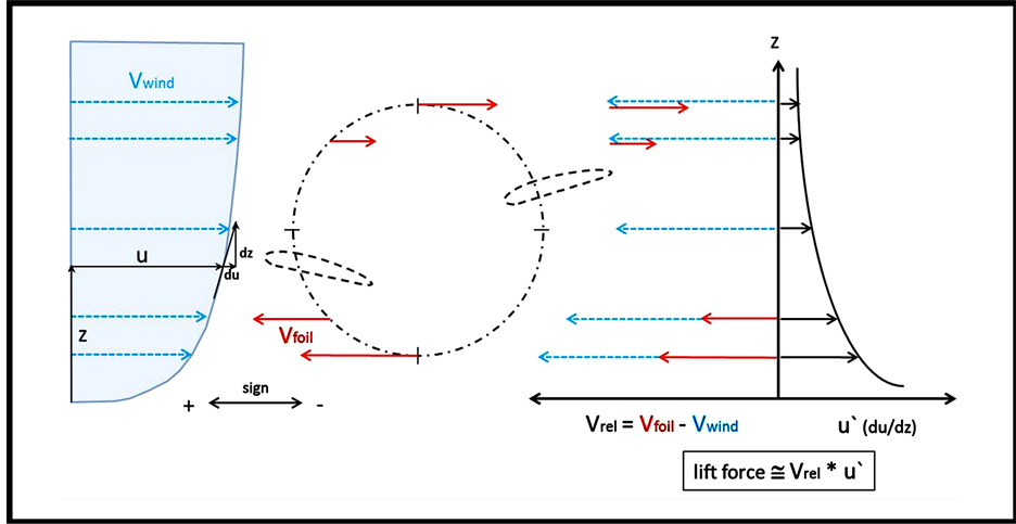
Figure 6. Characterization of relative wind velocity u (or Vwind) and the wind velocity gradient u' (du/dz) for understanding them with respect to a rotationally operating wind machine. The wind velocity u within the wind velocity gradient is equally termed Vwind in order to relate it to Vfoil for explaining the relative wind velocity Vrel.

Figure 7. Three different strategies for a technical approach to albatross-type flight (a) linear (b) rotational (c) intermediate combined system.
velocity which has to be added to the wind velocity within the velocity gradient.
It should be pointed out that the flight velocity of the albatross into the wind gradient changes as well in independence of the height above the sea surface. The albatross will fly with high velocity into the wind gradient close to the sea surface and then be pushed up while losing airspeed since kinetic energy is being converted into potential energy. High above the sea level where the full wind velocity is reached the albatross is even pushed forward by the wind before he is flying down towards the sea level while converting the potential energy of height into kinetic energy.
1) Linear wind gradient power system (WGPS)
In a linear WGPS Figure 7(a) an airfoil modeled according to the wing profile of the albatross is moving up and down changing its position within the air velocity gradient. It has been mentioned (Figure 4) that the albatross has an only weakly asymmetric wing profile compared to other large birds. But some asymmetry is still present with a consequence that an up-drift as known from airfoil technology and described by the lift coefficient cl is present [11] . But there are two differences—one is that the wind velocity gradient adds velocity in such a way that the velocity of the upper foil surface will be increased compared to the lower surface. This will add to the up-drift force by in principle increasing the cl value. Also normal aerodynamic up-drift (based on the characteristic wing profile of the albatross (Figure 4)) will occur.
The second difference will be that the airfoil when exposed to the maximum air velocity, within the gradient, will have been manipulated so that the potential energy can be harvested. This means that while changing its inclination (pitching angle γ) the air foil has to be returned to a lower position while providing energy which should be extractable in the form of electricity.
A simple mechanism which is accomplishing this task is shown in Figure 8. The airfoil has to achieve this function by changing its orientation with respect of the streaming direction of air. This can be achieved with e.g. an electro-mechanical control unit and the consequence would be that the airfoil would move up and down (by a short circular reversal path at the bottom and the top). This periodic linear movement is able to provide energy which e.g. can be transformed into rotational movement or directly converted into electricity via a linear electro-magnetic generator.
2) Rotational wind gradient power system (WGPS)
The rotational functional WGPS may be operated via a model structure as depicted in Figure 9. Two or more airfoils are mounted on a cantilever type arm which can be rotated. The power generated via rotating movements of the airfoils can be extracted either mechanically via a gear or electro-magnetically via an appropriate rotating induction generator. It is important to note that during rotation of the airfoils in the wind gradient the inclination of the wing profile has to be modified. Such a periodic adjustment of the wing inclination appears to be a major engineering challenge but several technologies are available. Also a more complicated change of the wing structure and profile (as observed in wing or fin structures of living animals) should be considered as aerodynamic strategy towards WGPS.
The adjustment of airfoils (rotor blades) during flight is a well-established necessity for helicopter flight technology. This is achieved via a wobbling disc technology which has reached a high level of engineering
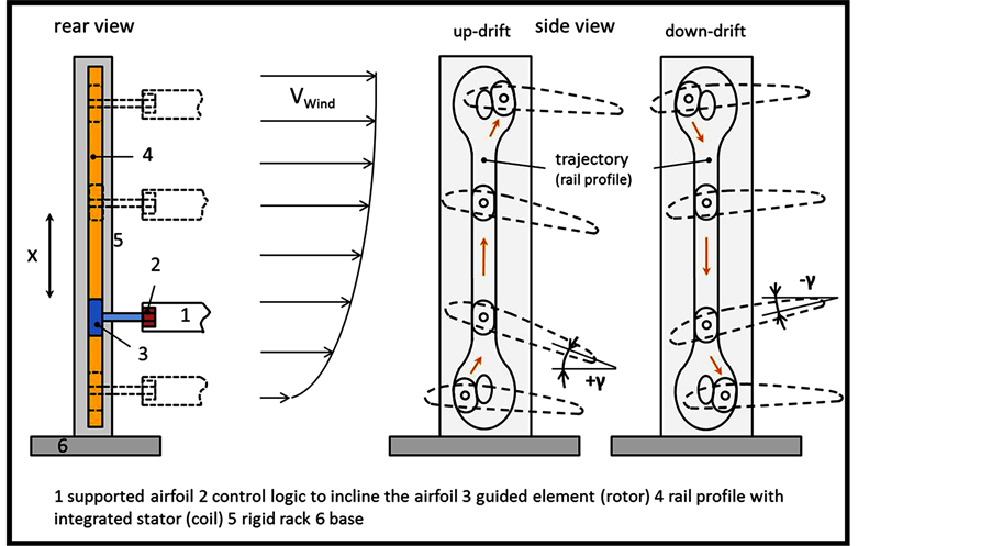
Figure 8. Linear WGP-System, schematic representation. Shown are the mechanical-electronic elements (left) and the positioning of the air-foils (right).

Figure 9. Rotational WGP-System, schematic representation. The mechanical set up is shown to the left, the air foil position to the right.
perfection. In principle such a technology could be adapted for WGP-Systems. But simpler alternatives maybe tested before in more basic models systems. Such alternatives have been considered and are explained in a sketch depicted in Figure 10. The rotating WGP-System operates via an energy yielding axis which can be used at the same time for steering the wing inclination in the desired wing positions during rotation. The rotating axis drives a bevel gear unit which powers a steering system. The steering system consists of two segmented rack-wheels which, while interacting periodically, turn the air foil into the desired position.
3) Other two-dimensional movements of WGPS Among several other possibilities a two dimensional movement of the energy harvesting WGPS has been considered. It activates linear up and down movements in combination with a horizontal movement of the basis of the structure. As seen from picture Figure 7(c), a trajectory of the wing in a number eight-form is resulting. In this case c horizontal movement is basically adjusting the airfoil. Both, the most simple structure of such a set up as well as mechanical forces acting upon the wings in their extreme positions are visualized in Figure 11.
More complicated two dimensional patterns of air foil trajectories are imaginable, considering that the albatross did evolve much more sophisticated flight patterns compared to that studied in this publication (compared to Figure 3).
WGP-Systems based on periodical change of air foil structure are also imaginable. In order to achieve a conversion of periodically generated potential and kinetic energy a well-tailored periodical change of form and profile of the air-foil could also be an attractive alternative. In principle a change of the wing profile could be

Figure 10. Example for steering system for wing inclination in a rotationally working albatross-type wind machine.

Figure 11. Combinatorial movement WGP-System, schematic representation. The wind velocity gradient (left) as well as the mechanical set up for down and up-drift movements (right) are presented.
induced via wireless triggered signals which periodically activate a mechanical mechanism reshaping the foil profile or the airfoil can be forced to change shape due to bending while rotating. A simple alternative has been studied according to Figure 12.
2.3. Preliminary Experimental Tests
It turned out to be a mayor challenge to generate a well-defined wind velocity gradient for testing of simple models of airfoils based on the albatross technology. To generate an adequate gradient-like air stream [12] [13] it had to be manipulated in a wind tunnel to change its profile from a homogeneous to an inhomogeneous (exponential-like or gradient-like) one. This can be accomplished by an entrance region Figure 13 with a well-defined roughness of installed surface structure, combined with vortex generators to shorten the distance to the region where the airstream is able to develop into a gradient form.
Further studies of the wind tunnel are necessary to get a higher quality of the gradient-shaped streaming behaviour. But first tests have shown that the rotating version of the albatross-type airfoil is indeed able to rotate. This is a first step towards a more profound investigation of albatross-type aerodynamic technology. Different airfoil models will have to be tested and energy recovery explored. Gradually more experience will be gained. A look at the development history of classical wind machines suggests that it will take some time until a reasonably high technological standard will be reached.
3. Theory and Discussion (Conclusion)
Our analysis up to now evidences that the albatross flight technology is based on quite complex physical-engineering boundary conditions. However the flight of albatross already looks back at 40 millions of years of evolution and the technology in biology has demonstrated a high standard. The albatross can fly for days without flapping wings.
In order to understand the physical principle and in order to understand the engineering challenges mathematical formulas expressing the main parameters need to be developed. In a very inspiring publication J. P. Barnes [5] has attempted to derive the essential underlying flight physics of the albatross. During this attempt the interchange of kinetic and potential energy has been considered together with the up-drift generating wind velocity gradient and the relevance of drag. An Equation (4) has been derived which describes the time derivative of the energy divided by the gravitational acceleration (unit mass) of the flying system (albatross):

Figure 12. Modified rotational WGP-System with changeable airfoil shape, schematic representation.

Figure 13. Set up for the investigation of the behaviour of a rotational albatross-typ airfoil model within a wind gradient airstream. (a) wind tunnel: radial fan with near 1600 m3/h (b) model with expanded polystyrene airfoils (c) entrance region (left) with model (right): generation of gradient-shaped wind profile by graded obstacles and vortex generators.
 (4)
(4)
This Equation (4) describes the time derivative of the energy that means the change of energy with time for an airfoil with given inclination, pitching angle γ, heading angle Ψ, gradient u', relative wind velocity V, lift L and drag D. The quantity nn describes the normal load factor (nn = lift/weight). The second term determines the importance of high lift-to-drag ratio under load. For the technical system we describe in our analysis these parameters will change during technical operation. For the rotating system the parameters will change in dependence of the rotational angle (α). In case of linear or combined rotational and linear systems they will also change in dependence of a displacement coordinate (x). For the most general case Equation (4) can accordingly be changed considering the variables α and x
 (5)
(5)
For a technical energy generator to work it has to yield a positive energy output during a full technical circle. For this to happen an integral of Equation (5) has to be taken for all angles α (0 ··· 360˚) and for all displacements x (0 ··· xmax and back to zero). Such integral would have the following form and meaning:
>0 positive energy output
 0 functioning without energy output (6)
<0 not functioning If this integral yields zero (=0) the energy of the system would be conserved, no energy output would be available. If the integral would be smaller zero (<0) energy would be lost and the system would cease to function. What engineering would have to accomplish is an integral which is yielding a positive value (>0) that is net energy output during one complete circle.
As seen from Equation (5) several parameters are involved which contribute to energy harvesting (first term

Figure 14. Sites for windand water velocity gradients which can be considered for albatross-type technology.
of Equation (4)) or energy loss (second term of Equation (4)). Of course the situation is quite complex and the outcome will significantly depend on the nature of the technical model system.
4. Outlook
Where can albatross-type aerodynamic technology be applied? There are numerous sites, apart from the first 15 meters above the ocean water and above plains where wind velocities could be strongly inhomogeneous. Such conditions exist or can be created artificially, for example between high rise buildings Figure 14 in modern cities. Here, the proposed technology could be implemented to provide energy for skyscrapers. The wind conditions, while being inhomogeneous, may be quite more stable and above all the wind speed is similar to that at wind power plants in such height. This could lead to effective solutions in wind energy systems, where a uniform wind velocity cannot be provided. A further advantage is the already existing or to be constructed high-rise building profile, which is generating the wind velocity profile. By using the architectural patterns of high rise buildings, a cheaper, more practical and more efficient wind technology may be achieved. Wind power plants could be integrated into architectural design.
Another challenge is energy harvesting via WGPS from wind streaming around mountain ridges Figure 14. Where high rise traditional wind turbines are not desired due to the visual impact on the landscape, wind energy could be generated via only 10 meter high, barely visible alternative installations based on the albatross principle. However, like with all new technical ideas, significant technical development work is still required.
WGPS could be installed together with off-shore wind power plants to take advantage of the gradients of wind velocity at lower heights (0 - 15 m). While the rotor blades of the power plants cover the homogeneous wind speed at higher altitude, the wind energy systems based on gradient could recover the wind energy closer to the sea level. This combination will reduce the high amount of space required, compared to when such systems are set up separately. This way it is possible to integrate such systems into already existing wind power parks.
The aggregation state of a medium needs not automatically be gas (air), it can also be liquid (water) when the velocity gradient develops as a consequence of friction from neighboring surfaces. The albatross technology is expected to work also when implemented in rivers, Figure 14. The streaming of water in rivers is known to be highly inhomogeneous and it is to be expected that hydro technology may be developed, which can largely be hidden under water.
Velocity gradients of air and water are quite common in nature and wind machines, which do not depend on homogeneous velocity conditions expected to have a technological future.
Acknowledgements
The authors thank Peter Piccottini for his persistent encouragement and his valuable advice. They would also like to thank Phil Barnes for helpful technical suggestions.
NOTES
*Corresponding author.