Synthesis and Surface Modification of Spindle-Type Magnetic Nanoparticles: Gold Coating and PEG Functionalization ()
1. Introduction
Over the last decade, many reports have been devoted to the development of new generations of ferric oxide colloids and magnetic nanoparticles, these nano-objects have very attractive properties, which has resulted in a strong demand on several domains as microelectronics, catalysis, water treatment, including applications as MRItraceable drug carriers, cancer cell inhibitors or tumor cell magnetolysis agents [1,2]. In particular, special attention has been paid to the formulation of nanoparticles with controlled morphology and narrow size distributions. In the case of hematite (α-Fe2O3), one-dimensional nanostructures with different morphologies such as wire-like, rod-like and belt-like or two-dimensional spherical, elongated (spindle), micro-ring, or pseudo-cubic ones have been elaborated. They are produced by forced hydrolysis of ferric salts. In general, the growth of monocristalline α-Fe2O3 takes from a few days using hydrothermal techniques to one week under forced hydrolysis at 100˚C [3]. The anisotropic growth of hematite is generally controlled by the presence of different anions like phosphates, sulfates, oxalates or hydroxide ions [4-6]. Hematite is also used as a raw material to produce metallic iron with high magnetic properties. The reduction of α-Fe2O3 to α-Fe(0) takes place at roughly 400˚C under a H2 atmosphere. The main challenge in hematite reduction at high temperature is the aggregation of particles, mainly provoked by the sintering phenomenon that occurs at the interfaces between particles. Furthermore, to prevent uncontrolled re-oxidation of iron, passivation techniques are used. The passivation of metal powders is typically done by growing an oxide layer over the surface of particles, covering its surface with a silica layer or with an inert metallic shell (gold, silver, platinum) creating core@shell structures [7-9]. Passivation of nanoparticles is also required for biocompatibility when in vivo biomedical applications are contemplated.
In this paper, we report the synthesis of spindle-type Fe@Au core@shell nanoparticles (Fe@Au NPs) produced by the reduction of spindle-type hematite nanoparticles and their subsequent gold plating through a transmetalation reaction (Scheme 1). Due to their ellipsoidal morphology and biocompatibility rendered by the gold passivation, magnetic Fe@Au NPs may have a tremendous potential for cancer therapy thanks to tumor cell magnetolysis process [10,11]. Aiming at this goal, we have functionalized their surface with polyethylene glycols (PEG), which is an important biocompatible polymer that facilitates the solubilization and long-term circulation of proteins, viruses and other biological macromolecules [12]. We have then functionalized PEGs by substituting both terminal hydroxyl groups with respectively a thiol group (SH) and a fluorescein tag thanks to fluorescein isothiocyanate (FITC), (Scheme 1). The resulting bi-functionalized molecule was grafted to NPs throughout the strong gold-thiol covalent bond and consequently the fluorescein tag gave to particles an optical contrast that could facilitate observations of treated cells by confocal microscopy in the case of magnetolysis therapy. It is nevertheless important to note that the surface labeling can be easily adapted providing specific targeting of cancer cells by tethering ligands such as folic acid, RGD peptides or growth factor (e.g. VEGF) ligands at the PEG extremity in place of the fluorescent dye. Although spindle-type Fe@Au nanoparticles have already been described, the displacement reaction of iron by gold without the need of any additional agent, i.e. reducing agents or microemulsion became an interesting option for the preparation of spindle-type Fe@Au core@shell nanoparticles [13-15].
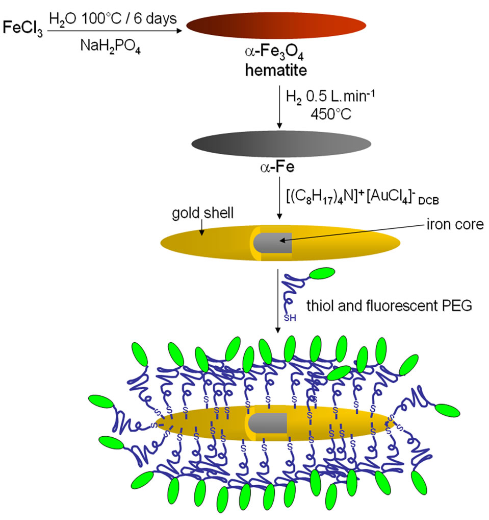
Scheme 1. General procedure to obtain the pegylated iron@gold (core@shell) NPs.
2. Experimental Section
2.1. Chemicals
Reactions were carried out under inert atmosphere using appropriate techniques. Iron(III) chloride hexahydrate (FeCl3·6H2O), trichloroethylene (C2HCl3), 1,2 dichlorobenzene (DCB), tetraoctylammonium bromide (TOAB) [C8H17]4N+ Br−, and auric acid (HAuCl4) were supplied by Sigma-Aldrich. H2N-PEG5000-STrt (α-amino-ω-tritylthio-poly(ethylene glycol) Mw = 5000 Dalton) was supplied by IRIS Biotech GMBH. Sodium phosphate monobasic (NaH2PO4) was supplied by Fluka. Ultra pure water 18.2 MΩ cm was obtained from a Thermo Scientific water purification device.
2.2. Characterization Techniques
The polyethylene glycol was verified by nuclear magnetic resonance (1H NMR, Bruker AC-200 MHz spectrometer). Structure and properties of iron and hematite were studied by X-ray diffractions (XRD, Bracket PW307) at 45 kV and 30 mA. The instrument used a Cu Kα radiation with a wavelength of 1.54060 Å, samples were placed in a glass holder and were scanned from 6 to 110˚, 2θ), transmission electron microscopy (TEM, JEOL JEM-1400), scanning electron microscopy (SEM, FEI XL30 ESEM LaB6) coupled to an energy dispersive analyzer (EDX, EDX Oxford/INCA). Surface modification of particles with the fluorescent polymers was analyzed with a Leica SPE confocal microscope using a 63 × 1.4 N.A. oil immersion objective. Magnetic properties of samples were investigated using a M2000/2100 hysteresis meter.
2.3. Synthesis of Hematite Spindle-Type Particles
The preparation of α-Fe2O3 particles was performed according to a method, which has been described elsewhere [4,16] and adapted for a larger scale (5 - 10 g) synthesis. Briefly, 5.41 g (0.02 M) of FeCl3·6H2O and 0.054 g (0.45 mM) of NaH2PO4 were dissolved in 1 L of ultra pure water and kept undisturbed during 6 days at 100˚C. Then, a filtration method to wash off sub-products (mainly salts) of hematite suspensions was applied.
The filtration system allowed particles to be continuously washed without drying or concentrating particles. The filtration system was composed by a ceramic hollow membrane coupled with a steel membrane housing. The suspension of particles was injected into this system, washed with ultra pure water until the suspension resistivity reached around 18 MW cm at room temperature and finally freeze-dried. This filtration method, combined to freeze-drying procedure, prevented hematite from agglomeration and ensured the full dispersion of lyophilized nanoparticles.
2.4. Hematite Reduction to Iron(0)
The non-agglomerated hematite powders (10 g) obtained above was calcinated in a modified furnace chamber at 450˚C under a continuous H2 flow (0.5 L min−1) during 4 h. The temperature was controlled by a PID-controller included in the tube furnace (Pirox). The vertical tube furnace was modified to introduce a vertical column support adapted to spread H2 through the sample (Scheme 2). The home-made column support came from a modified Pirex buchner filter funnel lengthen in bottom. The column incorporated a sintered silica distributor in bottom, and a quartz wool was placed on top to prevent the fluidized powder to escape from the column.
The whole particles turned from reddish to black indicating conversion of Fe(III) into Fe(0). After cooling under a N2 stream, the column was pulled down and trichloroethylene (20 mL) was added under N2 flow to avoid oxidation of the resulting α-Fe(0) NPs, which were kept into this solvent for further experiments. Very interestingly, it should be mentioned that no sintering was observed during this step.
2.5. Surface Modification of Iron Particles
Synthesis of FITC-PEG5000-SH. H2N-PEG5000-STrt (250 mg, 0.05 mmol) was dissolved into CH2Cl2/DMF (5/1, v/v) 600 µL and then FITC (19.5 mg, 0.25 mmol) and Et3N (50 µL, 0.5 mmol) were added. The mixture was stirred overnight and diethyl ether was then added. The precipitated was filtered off, washed with ether and then dried over vacuo. S-Trityl protecting group was then removed with TFA to lead, after precipitation with diethyl ether, the desired thiol, Fluorescein-PEG5000-SH with 90% overall yield as a yellow-orange solid.
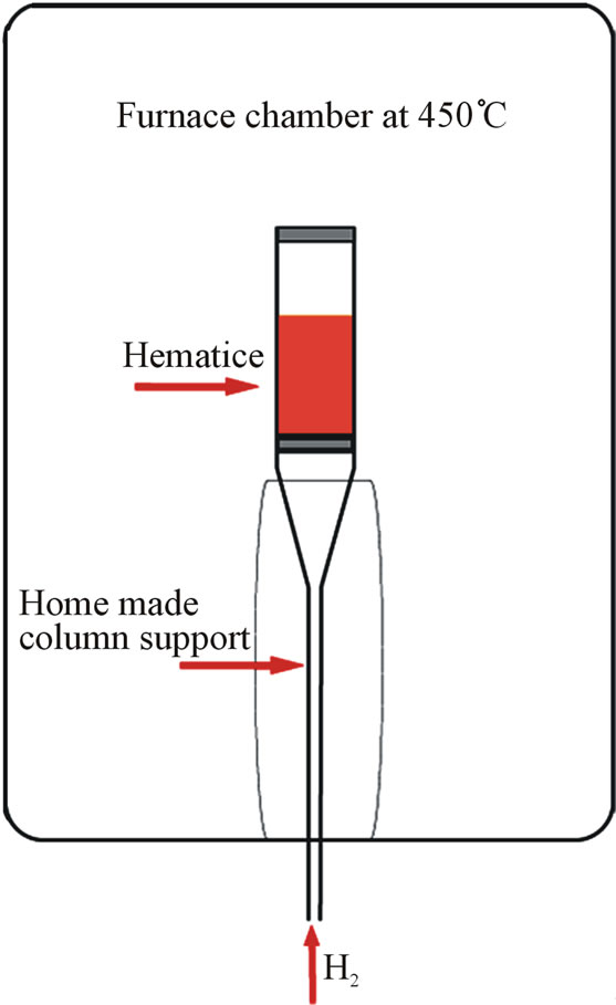
Scheme 2. Furnace scheme of α-Fe2O3 powders reduction.
NMR analysis of PEG. NMR 1H (d ppm, D2O, 200 MHz): 2.3 - 2.65 (m, 4 H, CH2SH, CH2CONH), 3.11 - 3.38 (m, (CH2O, CH2NH, 310 H], 6.43 - 6.63 (m, 6 H, H aromatic FITC), 7.02 (d, 1 H, J 8.1 Hz, H aromatic FITC), 7.57 - 7.62 (m, 1 H, H aromatic FITC), 7.80 - 7.83 (m, 2 H, H aromatic FITC).
Fe@Au NPs preparation. Gold coating of α-Fe(0) NPs was adapted and performed according to a described procedure [17]. First, hydrophobized gold(III) salt [(C8H17)4N]+[AuCl4]− were obtained from a phase transfer after mixing solutions of TOAB in DCB and aqueous HAuCl4 under vigorous stirring. [(C8H17)4N]+[AuCl4]− (290 mg, 0.36 mmol) were dissolved into 20 mL of DCB and added 100 mg of NPs under N2 atmosphere, the mixture were then heated at 90˚C for 2 h while kept under inert atmosphere and maintained under mechanical stirring. The reaction was quenched by adding 40 mL of absolute ethanol (EtOH). Fe@Au NPs were subjected to centrifugation/washing cycles with absolute EtOH (five times). Finally, particles were suspended into absolute EtOH and kept under a N2 atmosphere for further experiments.
Surface modification of Fe@Au NPs. 500 µL of the Fe@Au NPs stock suspension (10 mg·mL−1 in absolute EtOH) were degassed. Then, 500 µL of freshly made fluorescein-PEG5000-SH stock solution (10 mM in ultra pure water), which was previously degassed and filtered (0.22 µm, cellulose acetate), was added under N2. The resulting mixture was then stirred for 2 h under N2. Pegylated Fe@Au NPs were purified by several centrifugation/resuspension cycles into ultra pure water until the fluorescence signal of discarded water reached background level. Finally, FITC-PEG5000-labelled Fe@Au NPs were suspended into ultra pure water (1 mL) and further analyzed by TEM and confocal microscope to evidence functionalization.
3. Results and Discussion
3.1. Morphology and Structure of Hematite and Iron NPs
α-Fe2O3 and α-Fe(0) NPs resulting from the reduction process were analyzed by TEM and X-ray spectroscopy. The morphology and dimensions of particles were evaluated throughout a series of TEM pictures counting approximately 200 particles. Figure 1 displays a typical single particle of α-Fe2O3 (A) and α-Fe(0) NPs (B). It is important to mention that the shape of particles kept undisturbed during the whole process of reduction of the oxide into a metal phase. The average sizes measured from the TEM pictures were 580 (± 50) nm in length and of 80 (± 5) nm in width.
Figure 1 presents also the XRD patterns of both hematite and iron. X-ray pattern (a) exhibits crystal planes
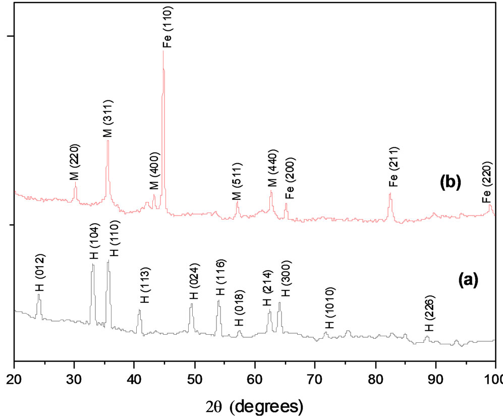

Figure 1. TEM pictures of (A) α-Fe2O3 and (B) α-Fe(0) NPs. X-ray diffraction patterns of α-Fe2O3 (a) and α-Fe(0) NPs (b), where planar peaks are hematite (H), iron (Fe) and magnetite (M).
corresponding only to Hematite. Pattern (b) shows two main phases, iron and magnetite. In (b), the crystallite sizes were estimated using the Scherrer equation with the characteristic reflections corresponding to iron (110) and magnetite (311), and were evaluated to 23 and 20 nm respectively. [18] Further magnetization measurements (see Section 3.4) are conjugated to these values to quantify the magnetic part of particles.
3.2. Fe@Au NPs Structure
Figure 2 shows the X-ray diffraction pattern of Fe@Au NPs. In this spectrum we have observed the characteristic peaks of iron, gold and magnetite, iron and gold peaks are overlapped at the diffractions peaks of 2q = 43.2˚, 62.7˚ and 82.43˚. Single peaks of gold and iron at 77.7˚ and 98.8˚ are respectively detected. It is as well observed the presence of magnetite as seen in Figure 1 (b). The core-shell structures of iron and gold were also corrobarated by SEM-EDX microscopy, Figure 3 presents the microanalysis of NPs presented in the inset of Figure 3. The EDX spectrum exhibits peaks for Fe, O, P and Au. The presence of Phosphorus is due to the phosphate introduction during the synthesis of hematite, the weak gold signal is due to the thin gold coating shell (see next section). These studies carried out by and XRD and SEM-EDX illustrate the coating of Fe@Au NPs and demonstrate that the presence of magnetite does not disturb the smooth reaction process, where a shell layer formation and core metal consumption occur simultaneously between surface Fe atoms of α-Fe(0) NPs and Au(III) ions of [(C8H17)4N]+[AuCl4]− in a non aqueous solvent.