Journal of Biomedical Science and Engineering
Vol. 5 No. 3 (2012) , Article ID: 18101 , 13 pages DOI:10.4236/jbise.2012.53016
FPGA implementation of fractal patterns classifier for multiple cardiac arrhythmias detection
![]()
Department of Electrical Engineering, Kao-Yuan University, Kaohsiung City, Taiwan
Email: eechl53@cc.kyu.edu.tw
Received 2 December 2011; revised 30 December 2011; accepted 29 January 2012
Keywords: Field-Programmable Gate Array (FPGA); Fractal Dimension Transformation (FDT); Fractal Dimension (FD); Probabilistic Neural Network (PNN)
ABSTRACT
This paper proposes the fractal patterns classifier for multiple cardiac arrhythmias on field-programmable gate array (FPGA) device. Fractal dimension transformation (FDT) is employed to adjoin the fractal features of QRS-complex, including the supraventricular ectopic beat, bundle branch ectopic beat, and ventricular ectopic beat. FDT with fractal dimension (FD) is addressed for constructing various symptomatic patterns, which can produce family functions and enhance features, making clear differences between normal and unhealthy subjects. The probabilistic neural network (PNN) is proposed for recognizing multiple cardiac arrhythmias. Numerical experiments verify the efficiency and higher accuracy with the software simulation in order to formulate the mathematical model logical circuits. FDT results in data self-similarity for the same arrhythmia category, the number of dataset requirement and PNN architecture can be reduced. Its simplified model can be easily embedded in the FPGA chip. The prototype classifier is tested using the MIT-BIH arrhythmia database, and the tests reveal its practicality for monitoring ECG signals.
1. INTRODUCTION
The electrocardiogram (ECG) signal can be measured non-invasively by placing electrodes on the body surface that provides information of myocardium electric activity and heart physiological function. An ECG signal shows as an almost periodic signal, and can reveal symptomatic information in the dysfunction duration. Currently, portable and stationary monitoring devices have been used on healthcare systems. Holter recorder is a well-known portable device and used to record the electrical activity with surface electrodes placed on the chest. However, its diagnostics is off-line analysis from the recorded data, and uses a cardiogram to identify arrhythmic types of the patients. Stationary monitors, such as dedicated or PCbased devices, have also been used on healthcare systems, which results in expensive solutions and limiting the portability [1,2]. Since telemedicine has also been used to acquire patient’s information, and has portable configuration for patient monitoring in remote non-clinical environments, it can be used in home healthcare, elder communities, and public place to acquire patient’s information. It has become a commonly used technology due to its low-cost, compactness, and short design-cycle. This remote device is an embedded hardware with FPGA, Bluetooth, RFID, and Zigbee. Via wireless transmission between the biosensor and supervision device, FPGA makes the ECG signal processing and sends digital signal to a remote monitor [3]. For a portable monitor design, FPGA device provides a promising solution to hardware implements.
FPGA device provides the flexibility and potential alternative to design hardware, including built-in DSP, analog and digital I/O, signal generation, communication, and specific functions for signal processing and controllers. It has been applied for digital filters design [4,5], signal analysis and classification [6,7], fault detection [8], and Fuzzy logic controller [9]. For signal analysis, transform methods have been used to extract features in the transform domain, such as fast Fourier transform (FFT) and wavelet transform (WT). However, the FFT technique is limited by the processing time, computational complexity, and the number of samples. The more samples, the more accurate parameters will be estimated. It will increase the memory requirement. WT can be chosen with a very desirable frequency and time characteristics, allowing the visualization with the short/broad window at the high/low frequencies. It is a dilated or constricted function by changing dilation and translation coefficients for feature extraction. WT process uses a several-structured filter bank to generalize several frequency bands containing decomposed signals [6,7]. Significant features are obtained at specific wavelet coefficients with a trial procedure of wavelet decomposition and experiences.
To overcome the drawbacks, an iterated function system (IFS) is proposed for modeling the non-linear interpolation function [10-14]. Its modification, the so-called FDT function, is simple in form and consists of sinusoiddal terms to the affine maps, making the model more flexible for processing irregular signals. FDT functions with FD are used to construct the fractal patterns from ECG signals in the time-domain, including the “Q-R Segment” and “R-S Segment”. The transform method results in data self-similarity and enhances the features for the same category. The PNN-based classifier is developed to perform the classification tasks. The performance of this method is presented and promising results are given for classification applications, such as the straightforward mathematical operation, flexible pattern mechanism, and high tolerance capability [15-17]. These algorithms can be easily programmed into the FPGA chip. The FPGA device has an inherent parallel architecture allowing designers to execute the multiple inputs and control loops simultaneously without slowing down the execution time and applications. From the test results, they appear to be computationally efficient and accurately recognize for patterns classification.
2. MATHEMATICAL BACKGROUND
2.1. Fractal Dimension Transformation (FDT)
An IFS has been proposed for image compression and signal modeling, and is capable of producing family functions with different fractal dimensions (FDs). It is a finite set for contraction mappings, and has been used to create images, various waveforms and patterns for medical image classification and biomedical signal analysis [10,11]. IFS is implemented with similarity maps, and the resulting data are self-similar. The significant removal of redundancy is related to the self-similarity of natural patterns. In modeling the pattern of a function or data sequence x[t], t = 1, 2, 3,  , N, the pth interpolation map Wp, p = 1, 2, 3,
  , P, can be presented as
 (1)
(1)
 (2)
(2)
For each map, Wp maps the data sequence xp[t] onto the subsequences with Np sampling data in the interval [Np1, Np2], and the maps can be constructed side by side. The remaining map parameters cp, dp, and fp can be solved by minimizing the sum of squared errors between the transformed data and the original data in the range of the pth map, and can be justified by the Collage Theorem [12,13]:
 (3)
(3)
where , Np = Np2 – Np1 + 1and N = N1 + N2 + N3 + ⋯ + Np + ⋯ + NP. To improve the constraint, non-linear interpolation is used to adjoin the data among the interpolation points, which makes the model more flexible for processing non-linear and irregular signals. Non-linear terms as sinusoidal functions can be added to Wp. The non-linear interpolation function can be represented as
 (4)
(4)
A fractal pattern of ECG signal can be adjoined with several segments such as P-R interval, P-R segment, Q-R-S complex, S-T segment, or Q-T interval. The nonlinear function with fractal dimension (FD) will change the ECG signals into fractal patterns at different scale parameters. FD must be a parameter between 1 and 2 for processing one-dimensional signals. The non-linear interpolation function, FDT with FD, can be modified as
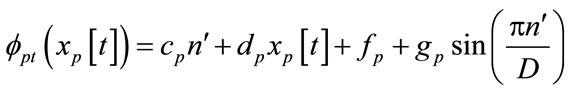 (5)
(5)
 (6)
(6)
where D is a FD parameter (1 < D < 2). The remaining map parameters cp, dp, fp, and gp can be solved by
 (7)
(7)
 (8)
(8)
Apply sequence data xp [t] are the sampling data from the ECG signals. The fractal patterns can be reconstructed as [14]
 (9)
(9)
Equations (5) and (6) are used to extract the features from the ECG signals, and Equation (9) is utilized to construct the fractal patterns of cardiac arrhythmias.
2.2. Artificial Neural Network (ANN)
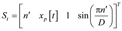
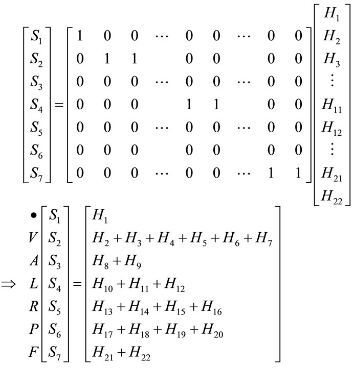
The PNN consists of four layers, including the input layer, hidden layer, summation layer, and output layer, that has the parallelism distributed process, learning, and pattern recognition ability. In this study, we have considered the sequence data xp[t], t=1, 2, 3,  , Np, with P segments from the ECG signal, and a fractal pattern F can be represented as
 (10)
(10)
The vector F can be also combined as F = [j11, j12, j13,  , j1N1|j21, j22, j23,
  , j2N2|…|jP1, jP2, jP3,
  , jPNP] = [f1, f2, f3,
  , fi,
, fi,  , fN], i = 1, 2, 3,
  , N, N = N1 + N2 + N3 +
  + NP, and each feature fi is connected to the input nodes of input layer. The number of input nodes is equal to the number N. The number of hidden nodes Hk (k = 1, 2, 3,
  , K) is equal to the number of training data, while the number of summation nodes Sj and output nodes Oj (j = 1, 2, 3,
  , m) equals to the types of cardiac arrhythmias. Therefore, its architecture can be easily to determined without any trial-and-error procedure. The weights
  (connecting the kth hidden node and the ith input node) and
  (connecting the jth summation node and the kth hidden node) are determined by K input-output training pairs. In the hidden node, a normalized Gaussian function Hk is applied to the Euclidean distance Ed between the unknown pattern F and K training patterns
 . The function Hk is inversely proportional to the distance Ed. If Ed approaches zero, the unknown pattern F is similar to any training data. This concept can be used for analyzing pattern relations. The output Oj can be computed by
 (11)
(11)
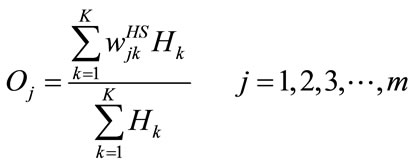 (12)
(12)
where the weights  are created by training data F(k) = [f1(k), f2(k), f3(k),
  , fN(k)], k=1, 2, 3,
  , k,
, k,  , K;
, K;
the weights  are the desired outputs associated with each stored pattern
 . The value of
  will be equal to “1” or “0”. The value will be set to be “1” when the kth training data belonged to the jth class; sk is the smoothing parameter. Finally, the maximum output Omax = [O1, O2, O3,
  , Oj,
, Oj,  , Om] indicates the type of cardiac arrhythmias.
In Equation (11), the smoothing parameter s1 = s2 = s3 =  = sK = s (s ¹ 0) would refine the classification accuracy. The non-linear optimization method, such as gradient descent method, steepest descent method or Newton-Raphson method [15-17], is employed to adjust the parameter s and minimize the error with iteration procedures. It is intended to minimize the predicted squared error function
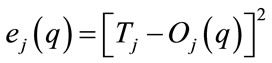 , and is updated by using pattern learning as
 (13)
(13)
where Tj is the desired output for training pattern , h is the learning rate, and q is the iteration number. The PNN based classifier has a dynamic and fast adaptation ability with continuity add-in or delete-off training data by automatically tuning the desired outputs and parameters s of hidden nodes.
3. FPGA IMPLEMENTATION
3.1. FPGA Development Environment
The field-programmable gate array (FPGA) is a semiconductor device that can be configured by the customer or the designer after manufacturing. It has the array architecture of logical elements, which can be used to design any logical functions to implement the given applications, such as an application-specific integrated circuit (ASIC). FPGA is also a programmability device, like programmable ROMs, and its programming techniques include antifuse-based device (Programmed Once) and static-memory-based device (Reprogrammed an Unlimited Number of Times). A typical FPGA consists of configurable logic blocks (CLB), input/output blocks (IOB), and programmable interconnects [4-9]. Each CLB can design the logical functions and latching data with combinational logic and sequential logic (AND, OR, Flipflops, and Registers). IOBs provide the interface between external pins and internal logics. Programmable intercomnects link the CLBs, I/O pins, and other resources on-chip memory through the routing paths, where interconnection among these blocks can be programmed by using hardware description language (HDL). Then, the designs can transferred the descriptions to gate-level netlists and dataflowflow on a chip. The prototype device can be implemented, tested, debugged, and modified as needed in a short design cycle.
Custom-design platforms have been provided to the FPGA implementation, such as Verilog, ModelSim, and Quartus II, and its development environment can simulate and verify the logic designs before initiating the compilation process [18-20]. However, HDL is a low level textbased programming language used for FPGA hardware design. Currently, LabVIEW extends the graphical programming tools to FPGA-based hardware. It has parallel execution, data acquisition, and floating-point arithmetic (Data Word Length: 8, 16, and 32 bit) functions to process signals on FPGA, and embeds specific functions for math, signal analysis/generation, comparison logic, linear/ non-linear control, analog and digital I/O, and timing. In this workspace, designers can quickly develop specific and reliable embedded systems containing FPGA-chips, real-time processor, and human machine interface (HMI). Graphical user interface for windows application has shorter design cycle, reprogrammability, and flexibility, which is much better than text-based languages. Under this development environment, we use saturation arithmetic functions to configure the combinational logics without prior complex digital design or electronic design automation (EDA) tools, and then to embed intelligent algorithms on the compact chip.
3.2. FDT Implementation with FPGA
An ECG signal is measured with the modified limb lead II (ML II), and its typical waveform consists of the Pwave, QRS-complex, and T-wave. The QRS-complex provides distinct information in monitoring heartbeats, which can be used to discriminate the arrhythmic types. Centered on the R-wave peak, the QRS-complex can be divided into the Q-R segment and R-S segment (P = 2). For 50 sampling points (25 points before R-peak and 25 points after R-peak, N = N1 + N2 = 50), the remaining map parameters can be solved by Equations (7) and (8) in the Matlab workspace. By using FD between 1 and 2, the fractal patterns are constructed with Equations (5), (6), and (9). The FDTs with fractal dimension D = 1.6 is chosen in this study. For a QRS-complex of normal beat (Patient Number: MIT-103), related parameters cp, dp, fp, and gp, p = 1, 2, are computed as shown in Table 1. The coefficients of four terms are assigned to construct FDT functions with 4 remaining map parameters for Q-R segment and R-S segment, respectively. Following the multiplication and addition of the FDT, the fractal fractures can be computed. However, the logical blocks only support the four fundamental operations of arithmetic. In Equation (5), special function 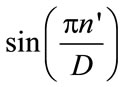 must be expanded a function into finite terms of Maclaurin series as
 (14)
(14)
where  and
and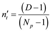 , w and
  are the constant coefficients; R, r = 0, 1, 2,
  , R, is the number of series term (R = 10 in this study); zr, r = 0, 1, 2,
 , R, represent the series coefficients and are also constant values. These coefficients can be computed and completed to verify the expanded function accuracy in the Matlab workspace, as shown in Table 1.
Figure 1 shows the structure of FDT logical block, in which 13 adders, 26 multipliers, and 17 constant coefficients are required to implement each FDT. Its CLB can design the function of feature extraction with combinational logical elements, and constant coefficients are stored in the memory elements. When each sampling data is applied to the FDT, each fractal feature is computed with multiplication and addition. This parallelism process completes the fractal pattern, and then each feature is applied to the PNN logical block.
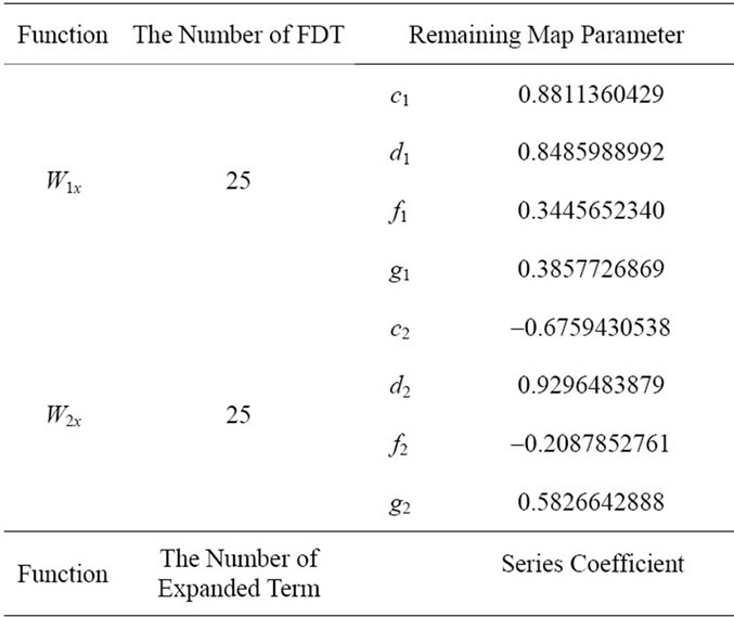

Table 1. Related data for FDTs.

Figure 1. The structure of FDT logical block.
3.3. PNN Implementation with FPGA
In this section, we focus on classifier design and collection of the annotated ECG beats for PNN training data. The ECG signals are obtained from the MIT-BIH arrhythmia database, including patient numbers: 100, 103, 107, 109, 111, 118, 119, 124, 200, 202, 207, 209, 212, 213, 214, 217, 221, 231, 232, and 233 [21]. ECG signals have various morphological information and waveforms, which can be classified into seven categories, including normal beat (·), premature ventricular contraction (V), atrial premature beat (A), right bundle branch block beat (R), left bundle branch block beat (L), paced beat (P), and fusion of paced and normal beat (F). Centered on the R-wave peak, the QRS-complex is divided into the Q-R segment and R-S segment. The FDTs with FD are utilized to construct various fractal patterns as shown in Figure 2. With data self-similarity, the preprocess resulting in the fractal patterns are similar for the same category, which can reduce the requirement of training data. The total number of fractal patterns are selected to be 1-, 6-, 2-, 3-, 4-, 4-, and 2-set data (K = 22) for the seven categories, respectively. These associated patterns could be expressed as weights , k = 1, 2, 3,
  , 22, i = 1, 2, 3,
  , 50, between the input and hidden layer. The weights
 , m = 1, 2, 3,
  , 7, between the hidden and summation layer are encoded as binary values with signal “1” denoting the seven categories while the rest of the weights are zero. The smoothing parameter s was adjusted by using the gradient descent method with 22-set training data. The optimal parameter s = 0.10942 can be computed in the Matlab workspace. For the convergent condition (Squared Error £ 10–4), PNN converges to the nearest local minimum for less than five learning cycles. The related data of the PNN-based classifier are shown in Table 2.
3.3.1. Hidden Node CLB
In the hidden layer, a normalized Gaussian function must be also expanded into a Maclaurin series as
 (15)
(15)
where div is dividend, div = 1 in this sudy,  and
and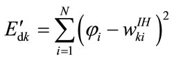 , d is the constant coefficient, and R is the number of series term (R = 6 in this study); yr are the series coefficients. Related data can be computed and stored in the memory elements as shown in Table 2. The

Figure 2. The the various fractal patterns for multiple cardiac arrhythmias.
Note: 1) No. 1: ·; 2) No. 2~7: V; 3) No. 8~9: A; 4) No. 10~12: L; 5) No. 13~16: R; 6) No. 17~20: P; 7) No. 21~22: F.


Table 2. Related data for PNN-based classifier.
term d can be computed with multiplication and addition. Then input the results to Gaussian function Hk. Figure 3 shows that the structure of hidden-node CLB, 106 adders, 63 multipliers, 1 divider, and 59 constant coefficients are required to implement each node Hk.
3.3.2. Summation-Node and Output-Node CLBs
For seven categories, the weighting factors , k = 1, 2, 3,
  , 22, j = 1, 2, 3,
  , 7, are encoded as binary values with signal “1” belonging to category j and the rest of the factors are zero. The weighting matrix [
 ]7´22 is sparse with 22 nonzero elements. The numerator of Equation (12) is a matrix vector computation, where each output Sj is formed by multiplying each of 22 outputs of the hidden node by one of 22 weighting factors, and can be presented as
 (16)
(16)
The number of addition and multiplication operations can be reduced leading to an increased speed in the arithmetic process. In the summation layer, the outputs of summation node Hk are computed with 15 adders. For the same category, their outputs of hidden nodes are summed in the summation-node CLB. The implementation of output node Oj would require 6 adders and 7 dividers, and can be presented as
 (17)
(17)

Figure 3. The structure of hidden-node logical block.
as shown by the denominator of Equation (12), the number of the addition operations can also be reduced. The structure of summation-node and output-node CLBs are shown in Figure 4.

Figure 4. The structure of summation-node and output-node logical block.
3.4. Overall Structure of the Proposed Classifier
In Figure 5, the overall structure of the proposed classifier divides into three stages: 1) signal preprocessing; 2) fractal feature extraction; and 3) heartbeat recognition with PNNbased classifier. In the preprocessing stage, ECG signals are acquired by using the amplifier and filter. The bandpass filter is used to remove unwanted frequency components, which comprise supply line frequency interference (50 Hz/60 Hz), baseline wander, and muscle noises. Thus, these noises do not affect the performance of the proposed classifier. ECG records are composed by a modified limb lead II (ML II) sampled at 360 Hz. Then R-peak waves are detected by the Peak detection algorithm. It begins by scanning for local maxima in the absolute value of ECG data. For certain window, the search continues to look for next larger value. If this search finishes without finding a larger maximum, the current maximum is assigned as the R-peak wave. The averaging window was chosen to be roughly the width of a typical QRS-complex. This window is at least 150 ms wide to allow for the wide QRS-complexes produced by V-heartbeats [22-24]. Centered on the detected R-peak, 25 sampling data are acquired including both Q-R segment (140 ms) and R-S segment (140 ms), respectively. In the second stage, these sampling data are converted to digital form (Signed 8-bit, 16-bit, or 32-bit Length Data) and then sent directly to the FDTs. The FDT CLBs with parallelism process are used to extract features and construct the fractal pattern. Finally, the classifier module integrates hidden-node, summation-node, and outputnode CLBs for cardiac arrhythmias recognition.
4. EXPERIMENTAL RESULTS AND DISCUSSIONS
The FPGA implementation of the proposed classifier is applied to examine multiple cardiac arrhythmias. With MIT-BIH arrhythmias database, the records of patient

Figure 5. The overall structure of proposed fractal patterns classifier.
numbers 107, 118, 119, 200, 209, 211, 214, 217, and 231 are selected for testing. Tested ECG signals were generated using LabVIEW and Matlab software on a PC Pentium-IV, 3.0 GHz, 480 MB RAM. The design platform of SOPC-NIOS II EDA/SOPC series (NIOS II-EP2C35 Chip, 700 K system gates, EEPROM) was used in this study. The ECG signals have been digitized and bandpass filtered, thus lowand high-frequency noises appears smaller in amplitude [21]. Signal preprocesses, such as R-peak detection and QRS-complex extraction, can be performed in LabVIEW and Matlab software. It is important that the signals delivered to the FPGA must be digital type. As they are intrinsically digital formats (8-bit Format), they can be directly sent to FPGA design platform. For recorded (Training Data) and unrecorded data, the proposed classifier was tested with accuracy and computational efficiency, and compares with the results in FPGA module and Matlab workspace.
4.1. Comparison with the Fractal Patterns in FDT CLB and in Matlab Workspace
The proposed classifier is tested with the software simulation, in order to examine the implementation of FPGA modules. After the designated modules, the designated circuit can be programmed into the FPGA chip through the download cable. In feature extraction, fractal features are extracted by using 50 FDTs. Then 50 features are reconstructed into one fractal pattern. Since the FDT module is a simplified module, it is worth noting that each FDT function must be first examined before programming them into the FPGA chip. The average fractal patterns from the same category are obtained from the selected patients. For training data, fractal patterns are computed by FDT module and high-level programming language (HLPL) in the Matlab workspace, respectively. Figure 6 shows the comparison fractal patterns in FDT module and Matlab workspace. The asterisk-line stands for the computed data with HLPL, and plus-sign-line is the computed data with FDT module Through cursory observation, nice inosculations can be seen between them, such as the fractal patterns of normal heartbeat, V-heartbeat, and F-heartbeat (Patient Numbers: 100, 107, 119, and 200). The differences are less than 0.2 as shown by the circle-line in Figure 6. This confirms that the proposed FDT module has high confidence of computation performance for reconstructing fractal patterns.
4.2. Classification Tests
The learning performance of the proposed classifier was tested with 22-set training data. In the learning stage, the optimal parameter s can be computed in the Matlab workspace. The proposed method has a fast learning process with slight iteration for adjusting parameter s. It takes 0.195 seconds to classify the 22-set training data into 7 categories. Then this optimal value was used to determine the parameter s of 22 hidden-node modules and was obtain to minimize the misclassification errors. Under the optimal parameter, decision boundaries can become increasingly non-linear, the network approaches a nearest neighboring classifier. In the recalling stage, all outputs
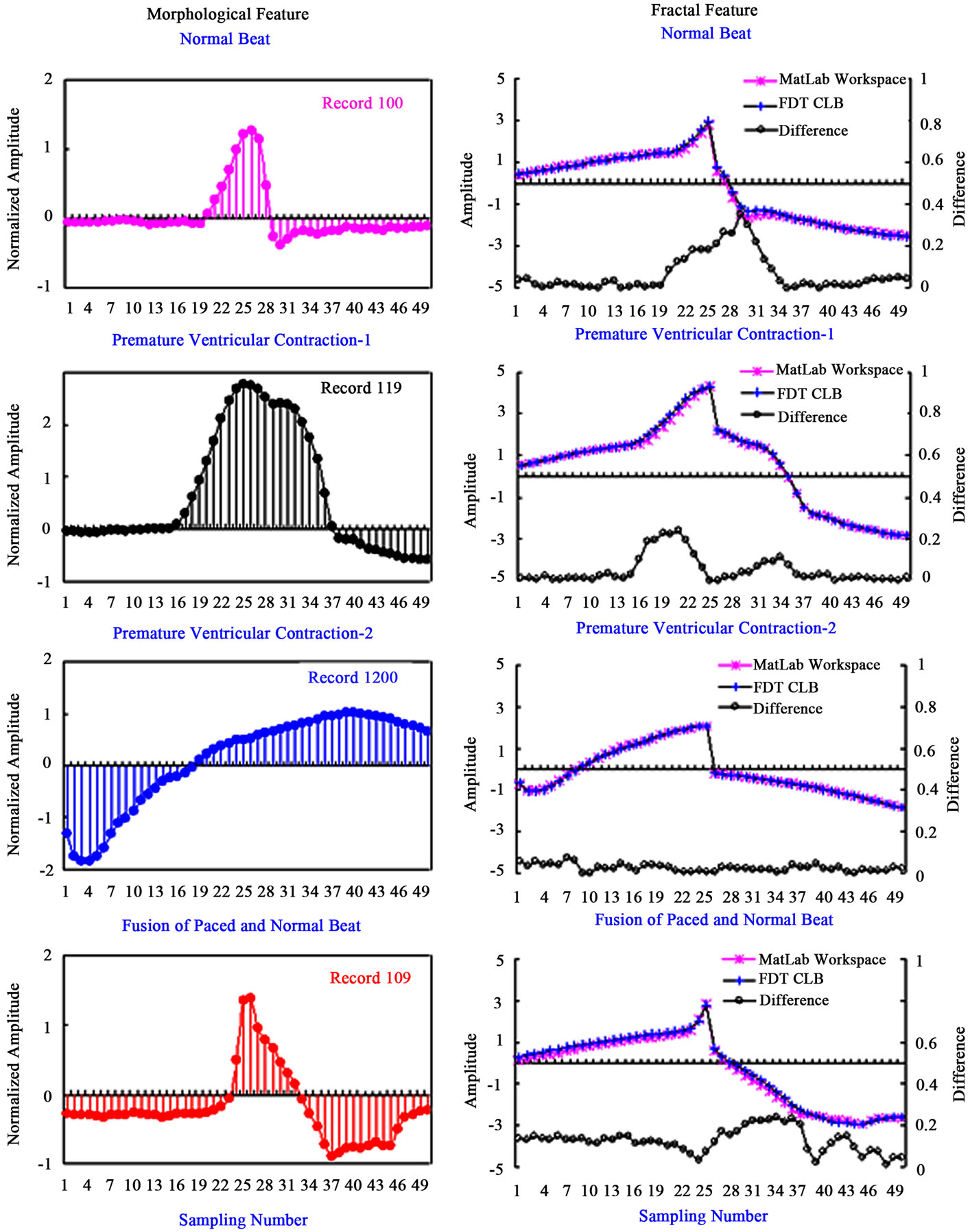
Figure 6. Compare with the fractal patterns in FDT module and in Matlab workspace.
approach the desired targets for 7 categories. The output values of the proposed classifier are shown in Figure 7. This confirms that the proposed classifier has nice learning performance.
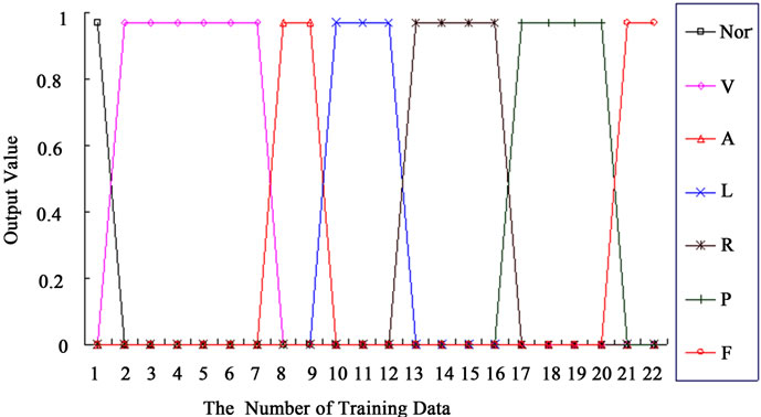
Figure 7. Output target value of the proposed classifier.
Note: 1) No. 1: ·; 2) No. 2-7: V; 3) No. 8-9: A; 4) No. 10-12: L; 5) No. 13-16: R; 6) No. 17-20: P; 7) No. 21-22: F.
Clinical diagnostic subjects have multiple cardiac arrhythmias such as supraventricular ectopic beat, ventricular ectopic beat, bundle branch ectopic beat, fusion, and paced beats. For example, patient number 200 has normal heartbeats and V-heartbeats with annotation labels in 1.5 minute segment. Test results reveal that the accuracy is 94% as shown in Table 3. The processes recognized 38 V-heartbeats with 6 failures, and the expected sensitivity as the fraction of category V correctly classified is 84.2%, and the specificity for normal heartbeats is 100%. The results confirm that the major category is the premature ventricular contraction. Patient number 217 has V-heartbeats, P-heartbeats, and fusion heartbeats (F). As shown in Table 3, test results confirm that the major category is P. The processes recognized 94 P-heartbeats with 5 failures, the sensitivities for ectopic beats is 94.7%, and the accuracy is 95%. Through the experimental tests, the proposed classifier can also recognize multiple cardiac arrhythmias with good accuracy in the FPGA module.
4.3. Discussion
In this study, the parameters of FDT functions have been directly computed by Collage theorem. Each FDT CLB has the same structure; it only assigns the segmented remaining map parameters and series coefficients. Most of them are repeatable uses. Owing to the enhancement in features by the FDT functions, the number of training data, data storage, and processing needs can be reduced. For classification applications, artificial neural network (ANN) has been presented for this study. However, it has some limitations including very slow learning process, need iteration for updating weights, and need to determine the network architecture such as the number of hidden layers and hidden nodes. The weights, input-layer to hidden-layer and hidden-layer to output-layer, are always nonzero values. This will increase the requirement of the addition and multiplication operations and memory storage. In addition, sigmoid activation functions of hidden and output nodes [25] are difficult to implement the CLB mod-


Table 3. The results of multiple cardiac arrhythmias.
ules, including the arithmetic process and memory storage. The proposed classifier provides a promising way for implementing the portable bio-monitor and telemedicine.
5. CONCLUSION
A fractal-pattern classifier using FPGA for the realizetion of FDTs and PNN to recognize multiple cardiac arrhythmias was proposed. The FDT modules are employed to construct various fractal patterns, and make the difference between normal and unhealthy subjects. The PNN module is proposed for recognizing multiple cardiac arrhythmias. Numerical experiments have been conducted with MITBIH arrhythmia database. The proposed classifier has excellent computational efficiency, high accuracy, and flexibility for patterns recognition. Then programs were downloaded to the FPGA chip to integrate all the modules, real-time processing, compression, transmission and input/output. This prototype can be further integrated in telemedicine and portable non-invasive devices.
6. ACKNOWLEDGEMENTS
This work is supported in part by the National Science Council of Taiwan under contract number: NSC97-2614-E-244-001, August 1 2008- July 31 2009.
![]()
![]()
REFERENCES
- Hernandez, A.I., Mora, F., Villegas, M., Passariello, G. and Carrault, G. (2001) Real-time ECG transmission via internet for non-clinical applications. IEEE Transactions on Information Technology in Biomedicine, 5, 253-257. doi:10.1109/4233.945297
- Mori, Y., Yamauchi, M. and Kaneko, K. (2000) Design and implementation of the vital sign box for home healthcare. Proceeding of IEEE EMBS International Conference on Information Technology Applications in Biomedical, Arlington, 9-10 November 2000, 104-108.
- Guillen, J.M., Millet, J. and Cebrian, A. (2001) Design of a prototype for dynamic electrocardiography monitoring using GSM technology: GSM-holter. Proceeding of 23rd Annual International Conference-IEEE/EMBS, Istanbul, 25-28 October 2001.
- Chris, D. and Fred, H. (2000) FPGA signal processing using sigma-delta modulation-innovative combinations of techiques and hardware for system designers. IEEE Signal Processing Magazine, January, pp. 20-35.
- Abbes, A. and Shrutisagar, C. (2007) Power modeling and efficient FPGA implementation of FHT for signal processing. IEEE Transactions on Very Large Scale Integration Systems, 15, 286-295. doi:10.1109/TVLSI.2007.893606
- Huang, S.-J., Yang, T.-M. and Huang, J.-T. (2002) FPGA realization of wavelet transform for detection of electric power system disturbances. IEEE Transactions on Power Delivery, 17, 388-394. doi:10.1109/61.997905
- Chilo, J. and Lindblad, T. (2008) Hardware implementation of ID wavelet transform on an FPGA for infrasound signal classification. IEEE Transactions on Nuclear Science, 55, 2008, pp. 9-13. doi:10.1109/TNS.2007.914322
- Tiwari, A. and Tomko, K.A. (2005) Enhanced reliability of finite-state machines in FPGA through efficient fault detection and correction. IEEE Transactions on Reliability, 54, 459-467. doi:10.1109/TR.2005.853438
- Kim, D. (2000) An implementation of fuzzy logic controller on the reconfigurable FPGA system. IEEE Transactions on Industrial Electronics, 47, 703-715. doi:10.1109/41.847911
- Chen, D.R., Chang, R.F., Chen, C.J., Ho, M.F., Kuo, S.J., Chen, S.T., Hung, S.J. and Woo, K.M. (2005) Classification of breast ultrasound images using fractal feature. Clinical Imaging, 29, pp. 235-245. doi:10.1016/j.clinimag.2004.11.024
- Katz, M. (1988) Fractals and the analysis of waveforms. Computing in Biology and Medicine, 18, 145-156. doi:10.1016/0010-4825(88)90041-8
- Mazel, D.S. and Hayes, M.H. (1992) Using iterated function systems to model discrete sequences. IEEE Transaction on Signal Processing, 40, 1724-1734. doi:10.1109/78.143444
- Vines, G. and Hayes, M.H. III (1993) Nonlinear address maps in a one-dimensional fractal model. IEEE Transactions on Signal Processing, 41, 1721-1724. doi:10.1109/78.212754
- Barnsley, M. (1986) Fractal functions and interpolation. Constructive Approximation, 2, 303-329. doi:10.1007/BF01893434
- Seng, T.L., Khalid, M. and Tusof, R. (2002) Adaptive GRNN for the modeling of dynamic plants. Proceedings of the 2002 IEEE International Symposium on Intelligent Control, Vancouver, 27-30 October 2002, 217-222.
- Lin, C.-H. and Wang, C.-H. (2006) Adaptive wavelet networks for power quality detection and discrimination in a power system. IEEE Transactions on Power Delivery, 21, 1106-1113. doi:10.1109/TPWRD.2006.874105
- Lin, C.-H. Du, Y.-C. and Chen, T.S. (2008) Adaptive wavelet network for multiple cardiac arrhythmias recognition. Expert Systems with Applications, 34, 2601-2611. doi:10.1016/j.eswa.2007.05.008
- Fawcett, B.K. (1994) Tools to speed FPGA development. IEEE Spectrum, 31, 88-94. doi:10.1109/6.328732
- Anderson, I.D.L. and Khalid, M.A.S. (2009) SC build: A computer-aided design tool for design space exploration of embedded central processing unit cores for field-programmable gate arrays. IET Computer Digital Techniques, 3, 24-32. doi:10.1049/iet-cdt:20070120
- Arshak, K., Jafer, E., McDonagh, D. and Ibala, C.S. (2007) Modeling and simulation of wireless sensor system for health monitoring using HDL and simulink mixed environment. IET Computer Digital Techniques, 1, 508- 518. doi:10.1049/iet-cdt:20050206
- Goldberger, A.L., Amaral, L.A.N., Glass, L., Hausdorff, J.M., lvanov, P.Ch., Mark, R.G., Mietus, J.E., Moody, G.B., Peng, C.K. and Stanley, H.E. (2000) PhysioBank, physio toolkit, and PhysioNet: Components of a new research resource for complex physiologic signals. Circulation, 101, e215-e220.
- Urrusti, J.L. and Tompkins, W.J. (1993) Performance evaluation of an ECG QRS complex detection algorithm. Proceedings Annual International Conference of the IEEE Engineering in Medicine and Biology Society, San Diego, 28-31 October 1993, 800-801.
- Nambakhsh, M.S., Tavakoli, V. and Sahba, N. (2008) FPGA-core defibrillator using wavelet-fuzzy ECG arrhythmia classification. Proceeding of 30th Annual International IEEE EMBS Conference, Vancouver, 20-24 August 2008, 2673-2676.
- Shukla, A. and Macchiarulo, L. (2008) A fast and accurate FPGA based QRS detection system. Proceeding of 30th Annual International IEEE EMBS Conference, Vancouver, 20-24 August 2008, 4828-4831.
- Rzempoluck, E.J. (1998) Neural networks data analysis using SimulnetTM. Springer-Verlag Inc., New York. doi:10.1007/978-1-4612-1746-6