 International Journal of Intelligence Science, 2013, 3, 145-161 http://dx.doi.org/10.4236/ijis.2013.34016 Published Online October 2013 (http://www.scirp.org/journal/ijis) Hybrid Designing of a Neural System by Combining Fuzzy Logical Framework and PSVM for Visual Haze-Free Task Hong Hu, Liang Pang, Dongping Tian, Zhongzhi Shi Key Laboratory of Intelligent Information Processing, Institute of Computing Technology, Chinese Academy of Sciences, Beijing, China Email: huhong@ict.ac.cn, pangl@ics.ict.ac.cn, tiandp@ics.ict.ac.cn, shizz@ics.ict.ac.cn Received June 28, 2013; revised August 25, 2013; accepted September 5, 2013 Copyright © 2013 Hong Hu et al. This is an open access article distributed under the Creative Commons Attribution License, which permits unrestricted use, distribution, and reproduction in any medium, provided the original work is properly cited. ABSTRACT Brain-like computer research and development have been growing rapidly in recent years. It is necessary to design large scale dynamical neural networks (more than 106 neurons) to simulate complex process of our brain. But such a kind of task is not easy to achieve only based on the analysis of partial differential equations, especially for those complex neu- ral models, e.g. Rose-Hindmarsh (RH) model. So in this paper, we develop a novel approach by combining fuzzy logi- cal designing with Proximal Suppo rt Vector Machine Classifiers (PSVM) learning in the designing of large scale neural networks. Particularly, our approach can effectively simplify the designing process, which is crucial for both cognition science and neural science. At last, we conduct our approach on an artificial neur al system with more than 108 neurons for haze-free task, and the experimental results show that texture features extracted by fuzzy logic can effectively in- crease the texture information entropy and improve the effect of haze-removing in some degree. Keywords: Artificial Brain Research; Brain-Like Computer; Fuzzy Logic; Neural Network; Machine Learning; Hopfield Neur al Network; Bounded Fuzzy Operator 1. Introduction Driven by rapid ongoing advances in computer hardware, neuroscience and computer science, artificial brain re- search and development are blossoming [1]. The repre- sentative work is the Blue Brain Project, which has simulated about 1 million neurons in cortical columns and included considerable biological detail to reflect spa- tial structure, connectivity statistics and other neural properties [2]. The more recent work of a large-scale model for the functioning brain is reported in the famous journal Science, which is done by the group of Chris Eli- asmith’s group [3]. In order to bridge the gap between neural activity and biological function, Chris Eliasmith’s group presented a 2.5-million-neuron model of the brain (called “Spaun”) to exhibit many different behaviors. Among these large scale visual cortex simulations, the visual cortex simulations are most concerned. The two simulations aforementioned are all about the visual cor- tex. The number of neurons in cortex is enormous. Ac- cording to [4], the total number in area 17 of the visual cortex of one he mispher e is close to 160,000,0 00. Fo r the total cortical thickness th e numerical density of synapses is 276,000,000 per mm 3 of tissue. It is almost impossible to design or analyze a neural network with more than 108 neurons only based on partial differential equations. The nonlinear complexity of our brain prevents our progress from simulating useful and versatile functions of our cortex system. Many studies only deal with simple neural networks with simple functions, and the connection ma- trices should be simplified. The visual functions simu- lated by “Blue Brain Project” and “Spaun” are so simple that they are nothing in the traditional pattern recogni- tion. On the other hand, logic inference plays a very impor- tant role in our cognition. With the help of logical design, the things become simple, and this is the reason why computer science has made great progress. There are more th an 108 transistors in a CPU today. Why don’t we use similar techniques to build complex neural networks? The answer is yes. As our brains work in the non Turing computable way, fuzzy logic rather than Boolean logic should be used. For this purpose, we introduce a new concept-fuzzy logical framework of a neural network. Fuzzy logic is not a new topic in science, but it is really very fundamental and useful. If the function of a dy- namical neural network can be described by fuzzy logical formulas, it can greatly help us to understand behavior of C opyright © 2013 SciRes. IJIS 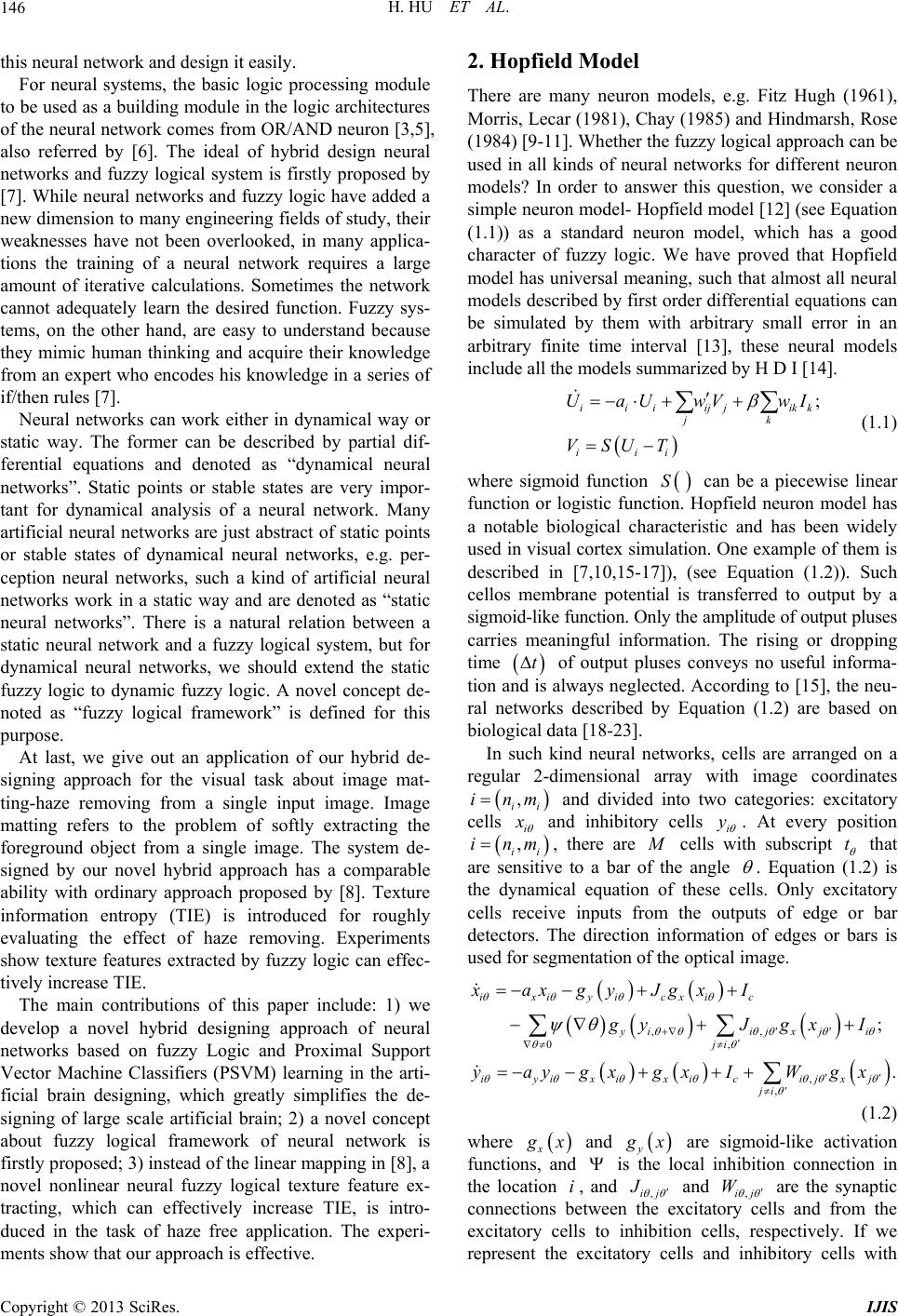 H. HU ET AL. 146 this neural network and design it easily. For neural systems, the basic logic processing module to be used as a bu ilding module in the logic arch itectures of the neural network comes from OR/AND neuron [3,5], also referred by [6]. The ideal of hybrid design neural networks and fuzzy logical system is firstly proposed by [7]. While neural networks and fuzzy logic have added a new dimension to many engineering fields of study, their weaknesses have not been overlooked, in many applica- tions the training of a neural network requires a large amount of iterative calculations. Sometimes the network cannot adequately learn the desired function. Fuzzy sys- tems, on the other hand, are easy to understand because they mimic human thinking and acquire their knowledge from an expert who encodes his knowledge in a series of if/then rules [7]. Neural networks can work either in dynamical way or static way. The former can be described by partial dif- ferential equations and denoted as “dynamical neural networks”. Static points or stable states are very impor- tant for dynamical analysis of a neural network. Many artificial neural networks are just abstract of static points or stable states of dynamical neural networks, e.g. per- ception neural networks, such a kind of artificial neural networks work in a static way and are denoted as “static neural networks”. There is a natural relation between a static neural network and a fuzzy logical system, but for dynamical neural networks, we should extend the static fuzzy logic to dynamic fuzzy logic. A novel concept de- noted as “fuzzy logical framework” is defined for this purpose. At last, we give out an application of our hybrid de- signing approach for the visual task about image mat- ting-haze removing from a single input image. Image matting refers to the problem of softly extracting the foreground object from a single image. The system de- signed by our novel hybrid approach has a comparable ability with ordinary approach proposed by [8]. Texture information entropy (TIE) is introduced for roughly evaluating the effect of haze removing. Experiments show texture features extracted by fuzzy logic can effec- tively increase TIE. The main contributions of this paper include: 1) we develop a novel hybrid designing approach of neural networks based on fuzzy Logic and Proximal Support Vector Machine Classifiers (PSVM) learning in the arti- ficial brain designing, which greatly simplifies the de- signing of large scale artificial brain; 2) a novel concept about fuzzy logical framework of neural network is firstly proposed; 3) in stead of the lin ear mapping in [8], a novel nonlinear neural fuzzy logical texture feature ex- tracting, which can effectively increase TIE, is intro- duced in the task of haze free application. The experi- ments show that our approach is effective. 2. Hopfield Model There are many neuron models, e.g. Fitz Hugh (1961), Morris, Lecar (1981), Chay (1985) and Hindmarsh, Rose (1984) [9-1 1 ]. W h ether th e f uzzy logical approach can be used in all kinds of neural networks for different neuron models? In order to answer this question, we consider a simple neuron model- Hopfield model [12] (see Equation (1.1)) as a standard neuron model, which has a good character of fuzzy logic. We have proved that Hopfield model has universal meaning, such that almost all neural models described by first order differential equations can be simulated by them with arbitrary small error in an arbitrary finite time interval [13], these neural models include all the model s summarized by H D I [14]. ; iii ijjik jk iii UaU wVwI VSUT k (1.1) where sigmoid function S can be a piecewise linear function or logistic function. Hopfield neuron model has a notable biological characteristic and has been widely used in visual cortex simulation. One example of them is described in [7,10,15-17]), (see Equation (1.2)). Such cellos membrane potential is transferred to output by a sigmoid-like function. Only the amplitude of output pluses carries meaningful information. The rising or dropping time t of output pluses conveys no useful informa- tion and is always neglected. According to [15], the neu- ral networks described by Equation (1.2) are based on biological data [18 -23] . In such kind neural networks, cells are arranged on a regular 2-dimensional array with image coordinates , ii inm i and divided into two categories: excitatory cells and inhibitory cells i y . At every position , ii inm, there are cells with subscript t that are sensitive to a bar of the angle . Equation (1.2) is the dynamical equation of these cells. Only excitatory cells receive inputs from the outputs of edge or bar detectors. The direction information of edges or bars is used for segmentation of the optical image. ,, 0, , , ; . ixiyicxic yiijxj i ji iyixixicijxj ji xaxgyJgxI gyJ gxI yaygxgxI Wgx (1.2) where x x and y x are sigmoid-like activation functions, and is the local inhibition connection in the location , and ,ij iJ and ,ij W are the synaptic connections between the excitatory cells and from the excitatory cells to inhibition cells, respectively. If we represent the excitatory cells and inhibitory cells with Copyright © 2013 SciRes. IJIS 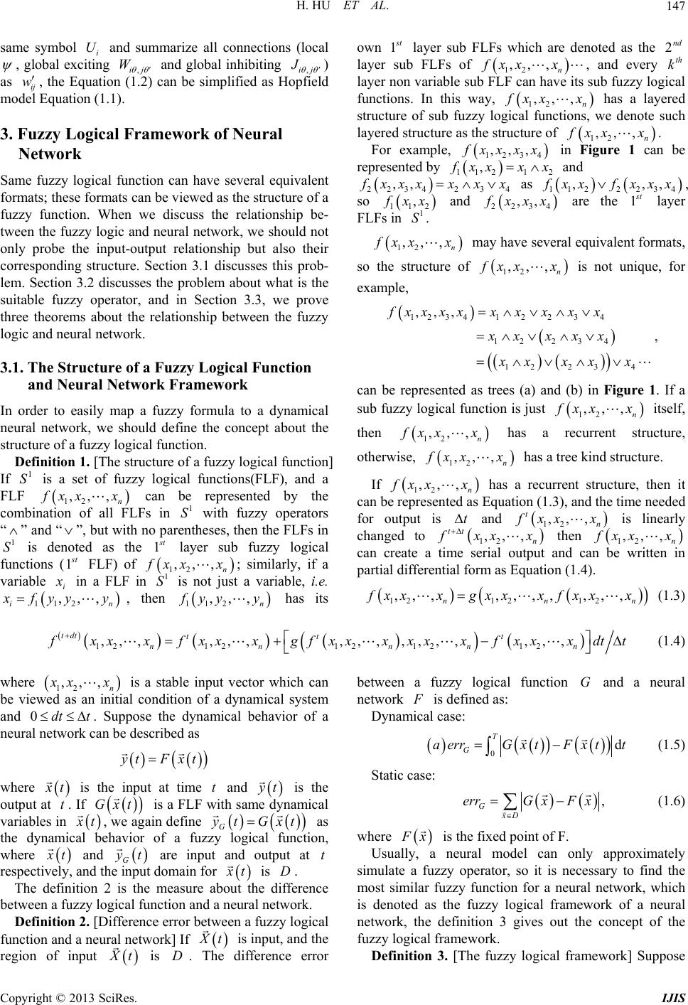 H. HU ET AL. Copyright © 2013 SciRes. IJIS 147 same symbol i and summarize all connections (local U , global exciting ,ij W and global inhibiting ,ij J ) as ij, the Equation (1.2) can be simplified as Hopfield model Equation (1.1). w 1 S 3. Fuzzy Logical Framework of Neural Network Same fuzzy logical function can have several equivalent formats; these formats can be viewed as the stru ct ure of a fuzzy function. When we discuss the relationship be- tween the fuzzy logic and neural network, we should not only probe the input-output relationship but also their corresponding structure. Section 3.1 discusses this prob- lem. Section 3.2 discusses the problem about what is the suitable fuzzy operator, and in Section 3.3, we prove three theorems about the relationship between the fuzzy logic and neural network. 3.1. The Structure of a Fuzzy Logical Function and Neural Network Framework In order to easily map a fuzzy formula to a dynamical neural network, we should define the concept about the structure of a fuzzy logical function. Definition 1. [The structure of a fuzzy logical function] If is a set of fuzzy logical functions(FLF), and a FLF 12 ,, , n xx x can be represented by the combination of all FLFs in with fuzzy operators “” and “”, but with no parentheses, then the FLFs in is denoted as the 1 1 S 1 S t layer sub fuzzy logical functions (1 t FLF) of 12 ,, , n xx x; similarly, if a variable in a FLF in is not just a variable, i.e. in i x 11 ,, 1 S 2, , then , n112 ,, yyy has its own 1 t layer sub FLnoted as the layer sub FLFs of Fs which are dend 2 12 ,,, n fxx x, and every th k layer non variable sub FLub fuzzy logical functions. In this way, F can have its s 12 ,,, n xx x has a layered structure of sub fuzzy logical functi suchons, he structure o we denote layered structure as t f 12 ,,, n xx x. For example 1234 ,,, Figure 1 can be xxxx in , 2 2 , 11 1 xx xxrepred by esent and 2 2342 fyy y 3 4 ,, xxxxxx as 12 234 , , 1 2 , xx fxx, so x 2 234 ,, xxx are the 1 t layer 1 21 , xx and FLFs i1 S. n 12 ,,, n xx x m equivalent formats, so the struc ay have several 12 ,,, n xx x is not unique, for ture of example, 1234 ,,,xxx 4 4 x x, Figure 1 1 22 3 12 2 x xxx xx xx d (b) in nctio 3 12 23 4 xx xx x can be represented as trees (a) an. If a sub fun is just 12 ,,, n fx zzy logical fu xx x itself, then n12 ,,, xx a recurrent structux hasre, e, otherwis 12 ,, xx , n xkind structure. If has a tree 12 ,,, n xx x has a recurrent structure, then it can be representes Equa time needed for output isd a ttion (1.3), and the and 1 t 2 ,,, n xx x changed to is linearly 12 ,,, tt n xx x then 12 ,,, n xx x can create a time serial output and can be written in pafferential fortial dirm as Equation (1.4). 1 , 2 ,,xx 12 ,,,, nn12 ,,, n xgxxx fxx x (1.3) 12 ,,, 1212 1212 ,,,,,, ,,,,,,, tdt t nn nnn tt xxfxx xxx xxx xfxx xdtt x gf (1.4) hwere 12 ,, n , xx an i k c is a stab iti le input vector wh networ ich can be viewal condition of a dynamical system and 0dt t. Suppose the dynamical behavior of a neuralan be describ ed as ed as n Fxtyt where t t at time is the inpu and t is the output at . If G is a FLF with same dynamical variables in xt t , we again define xt G yt as the dynamical behavior of a fuzzy logical function, where G t and G t are input and output at respectand the idomain for ively, nput t is D. The definition 2 is the measure abhe diout tfference between a fuzzy logical function and a neural network. Definition 2. [Difference error between a fuzzy logical function and a neural network] If t is input, and the region of input t is D. Tdifference error network he between a fuzzy logical function and a neural G is defis: Dynamical case: ned a 0d T G aerrGxtF t t (1.5) Static case: x , GxD errG xFx (1.6) where x lis the fixe d point of F. a n approximately Usualeural model can onl simulatzzy operator, so it is ne y, y e a fucessary to find the most similar fuzzy function for a neural network, which is denoted as the fuzzy logical framework of a neural network, the definition 3 gives out the concept of the fuzzy logical framework. Definition 3. [The fuzzy logical framework] Suppose 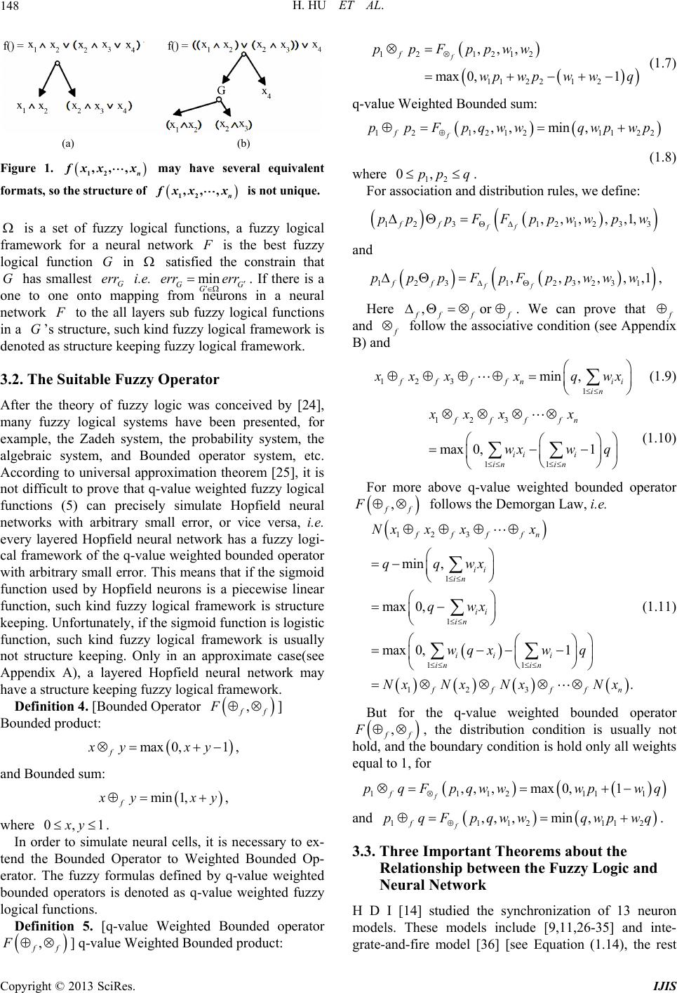 H. HU ET AL. 148 (a) (b) Figure 1. n xx x 12 ,,, may have several equivalent formats, so the structure of n fxx x 12 ,,, is not unique. is a set of fuzzy logic fuzzy logical al functions, a mework for a neural network fra is the best fuzzy log ne ical function G in satisfied the constrain that G has smallest G err i.e. m GG G errerr . If there is a one to one onto appi from neurons in a neural twork in m ng to th layercal functions in a G’s structure, such kind fuzzy logical framework is denoted as structure keeping fuzzy logical framework. 3.2. The Suitable Fuzzy Operator e alls sub logifuzzy After the theory of fuzzy logic was co many fuzzy logical systems have beenceived by [24], n presented, for example, the Zadeh system, the probability system, the algebraic system, and Bounded operator system, etc. According to universal approximation theorem [25], it is not difficult to prove that q-value weighted fuzzy logical functions (5) can precisely simulate Hopfield neural networks with arbitrary small error, or vice versa, i.e. every layered Hopfield neural network has a fuzzy logi- cal framework of the q-value weighted bounded operator with arbitrary small error. This means that if the sigmoid function used by Hopfield neurons is a piecewise linear function, such kind fuzzy logical framework is structure keeping. Unfortunately, if the sigmoid function is logistic function, such kind fuzzy logical framework is usually not structure keeping. Only in an approximate case(see Appendix A), a layered Hopfield neural network may have a structure keeping fuzzy logical framework. Definition 4. [Bounded Operator , f F ] Bounded product: 1, max 0, f xy xy and Bounded sum: min 1, f yx , y where 10, y. In order to simulate neural cells, it is necessary to ex- e Boundederator to Weighted Bounded Op- er tend th Op ator. The fuzzy formulas defined by q-value weighted bounded operators is denoted as q-value weighted fuzzy logical functions. Definition 5. [q-value Weighted Bounded operator , f F ] q-va 1212 ,,, f f pp Fppww 12 11 2212 max 0,1wpwpw wq (1.7) q-value Weighted Bounded sum: 12 1212 f f ppFpqww 2 (1 ) where 112 ,,, min,qwpwp .8 12 0,pp q association and . Fordistribution rules, we define: 3 12 312123 ,,, ,,1, ff ff pppFFppww pw and 12312323 1 ,,,,, ff ff ppFpFppwww , ,1 Here p ,or ff lue Weighted Bounded product: f . We can prove that and follow the associative condition (see Appe B) ndix and 123 1 min , fffn ii in xxx qwx (1.9) (1.10) For more above q-value weighted bounded operator 123 11 max 0,1 ffffn ii i in in xxx x wxw q , f F follows the Demorgan Law, i.e. 23fffn x xx 1 1 1 11 123 min , max 0, max 0,1 . f ii in ii in ii i in in ffff Nx qqwx qwx wq xwq Nx NxNxNx n (1.11) But for the q-value weighted bounded operator , f F ho , the distribution condition is usually not equal to 1, f ld, and the boundary condition is hold only all weights or 1,, ,max0,1 f f pqFpqwwwpwq 112111 and 111211 ,, ,min , f f pqFpqww qwpwq . 2 Three Important Theorems about the Relationship between the Fuzzy Logic and H Dn modinclude [9,11,26-35] and inte- 3.3. Neural Network I [14] studied the synchronization of 13 neuro els. These models grate-and-fire model [36] [see Equation (1.14), the rest Copyright © 2013 SciRes. IJIS  H. HU ET AL. 149 11 neuron models are all the special cases of the generalized model described by the ordinary differential Equation (1.16). 22 2. iaiiai aiiji j j xpxgx ft xx x (1.12) 22 2 , . ii iai iai aiiji j j xy xpygx ft xx x (1.13) 0 d dext syn vv It t (1.14) where and 0v 00 0ifvt vt . Usually syn t is defined by Equation (1.15). syn spike spikes Itg ftt 12 exp expft A tt (1.15) In fact, if we introduce a new variable ii yx change, the Van-der-Pol generator [28] model can bed to Eqf Equuation (1.13) which is just a special case oation (1.16); for the integrate-and-fire model, if we use logistic function 1 1exp T to replace the step function, th model can also has the e integrate-and-fire form of the Equation (1.16). So the Equation (1.16) can 2 n be viewed as a general representation of almost all neuron models, if we can prove the Equation (1.16) can be simulated by a neural network based on the Hopfield neuron model [see Equation (1.1)], then almost all neuron models can be simulated in the same way. 11111121 ,,, n 22 22212 12 ,,, ,,, n nn nnnn axwfx xxu axwfx xxu axwfx xxu (1.16) where every 12 ,,, ,1 in xxxi n rtial differential in the fin, has the continuous paite hypercubic domain 112 2 ,, n b aba ,,, :0 n xt xttT. (1.17) is the fixed point ,b tof n Da of its trajectory space 12 TR x The Equationth i a Hopfield neural circuit which only has one cell winput k . ,1exp 1 iikkii ii k UwIaV UT (1.17) At the fixed poin t, every neuron works just lik ron in a perception neural network. Theorem 1 tries to sh e a neu- ow the condition of Equation (1.17) to simulate dis- junctive normal form (DNF) formula. The fixed point of Equation (1.17) can easily simulate binary logical opera- tors; on the other hand, a layered neural network can be simulated by a q-value weighted fuzzy logical function. Theorem 1 Suppose in Equation (1.17), 1 i a , and every ,0,0,1 ikk iki wTTkK , for more, 1, , i Si L is a class of index sets,every index , Cset i S is a s and ubset of 1,2,3, , then we 1. If have: 12 1, , ,,, i ll klL jS fxxx is a d noform (DNF) formula, isjunctive rmal and the class 1, , i CSi L is the class which has the following two characters: (1). for every , ij SS C,ijk SS SC j for all and ki (this condition assures that 12 ,,, k xx x has a simple the character l j S st form); (2). every i S has 1 j , where i SC, and any index sets SC have character 1 j , or if 1 j jS jS , there must be an index set such that i i SC i SSS (this condition a is the larg, ssures est) xed point of the neural described by formu C cellthen the fi Equation (1.17) can simulate the DNFla 12 1, , ,,, i l klL iS fxxx ii z with arbitrary small error, where , if the corres- ponding input ii z , or ii z if 1 ii z on (1 . 2. If a ne described by.17) can ural cell Equati simulate the Boolean formula 2 ,, k 1 , xx x with arbitrary small error, and l i iS is an item in the disjunctive normal form of 12 ,,, k xx x, i.e. ,,, 1fxx x 12 k at xr all jS1 j fol and 0 j x for all l jS , then i iS dex and 2 l S ound 1. l 3. If a couple of insets can be f in the formula 1 l S 12 ,,, kt S 1, , , lk l t xx x x , such that 1 12 1 ll t tS tS xx xed point 2 2 e ti z fals i z , thhe fi of the neural cell described by Equation (1.17) can’t simulate the formula en t 12 ,,, k xx x. Proof 1. If 1 t I , for all l tS , and 0 t I, for all l tS , because 1 i l iS , th see ind ext l S is a subseten for th Copyright © 2013 SciRes. IJIS  H. HU ET AL. 150 of 1,2,3, , , we have 1 1exp1 i UT 11 1exp1 1, l ii ik ki kK ii iS V wI T T so e xp 12 lim1, ,, ik Vfxxx . If 1, t tS ; 0, t tS condition of th and , then acce is thSC eorem: if ording to th 1 i iS , 12 , ,k xx if 1 i , then there is an i lim 0, i Vf x ; ndex set such that , then iS i SC ii SSS 12 lim1, ,, i Vfxxx k . Shen o w static error defined by Equat6) trends to 0. , theion (1. 2. If thepoint of the neural cell de Eqauti fixed scribed by on (1.17) can simulate the Boolean formula 12 ,,, k xwhich is not a constant with arbitrary x x small error, and for a definite binary input 12 ,,, k xx, then the arbitrary small error is achieved when trends to infinite and 0 l ii ikki kS UT wIT where l S is the set of the labels and 1 i I, for all l iS, and 0 i I, for all ition suppses that every wT K l iS ik . The ’s condotheorem ,0, i0,1 k ikT k , and 12 ,,, k xx are binary nr 0 or so if 2 ,, k umbe1, 1 , xx xs not a constant, when 12 ,,, k fxx x i 0, ther lime must be0 i V ; and when 2 ,, 1 k xx , it is necessary for lim 1 i V 1 fx, . at l ii i iS TT trends to minus lim 0 i V infinite and needs th lim1 i V l ii i iS TT trends to plus infinite. So ,, k x needs that if 1 ,fx 21x at 1 j x for all l jS and 0 j x for all l jS , in order to guarantee e hol is the static error ween the neural cell , kki x 1 must bd, here 12 ,1 ,2, ,, lim,, ,,0, ii i fxx errw wwT l i iS 12 ,1 ,2, ,,,,,,, kii iki fxx x errw wwT defined by Equation (1.6) bet described d by Equat ion (1. 17) an 12 ,,, k xx x is based on the si . mple fact that for a single neuron 3. The third part of the theorem iis monotone on every input i V which can be i z or 1i z. An example of above theoreme is that th or fu e ed byquation (1.1) has a la he nction can’t be simulated by the neuron described by Equation (1.17). If thneural network dscribe E yered structure, the fixed point of a neuron at t non-input layer l is ,,,1, ,, liliklii k li li UwVa VSUT (1.18) Equation (1.18) is just a perception neur al network, so a perception neural network can be view of static points or stable states of a real described by Equat i o n ( 1. 18 ). red neural network can be si ed as an abstract neural network Theorem 2 shows the fact that a continuous function can be simulated by a layered Hopfield neural network just like a multi layered perception neural network with arbitrary small erro r, and a laye mulated by a q-value weighted fuzzy logical function. Theorem 2 is directly from the universal approximation theorem [25,37]’s proof. Theorem 2 If 1,, m xx is a continuous mapping from 0,1 m to 0,1 , for any 0, we can build a layered neural network defined by Equation (1.18), and its fixed point can be viewedontinuous map as a c 1 1 ,,, ,, mqm11 ,, , m xx FFxx from 0,1m1xx to 0, , such that 11 ,, ,, mm Fx x fx x , here 12 ,,, m xx are k inputs of the neural network. For more, for an ned by on (which has arbitr Equaary layer ti1 ed neur ) al netwo ark fixe defi d point func tion .17 ,, m1 xx, we can find a q-value fuzzyction logical fun 111 1 ,,,, ,,,, mmqm xx FxxmFxx of weighted Bounded operator , such that 11 ,,,, . mm x xFxxF nt neu networks described by the Equation (1.1 Theorem 3 tries to prove that all kind recurreral 6) can be simu- lated by Hopfield neural networks described by Equation (1.1). The ordinary differential Equation (1.16) has a strong ability to describe neural phenomena. The neural network described by Equation (1.16) can have feedback. For the sake of the existence of feedback of a recurrent neural network, chaos will occur in such a neural net- work. As we known, the important characteristics of chaotic dynamics, i.e., aperiodic dynamics in determinis- tic systems are the apparent irregularity of time traces and the divergence of the trajectories over time (starting from two nearby initial conditions). Any small error in the calculation of a chaotic deterministic system will cause unpredictable divergence of the trajectories over time, i.e. such kind neural networks may behave very differently under different precise calculations. So any small difference between two approximations of a tra- jectory of a chaotic recurrent neural network may create two totally different approx imate results of this trajectory. Fortunately, all animals have only limited life and the Copyright © 2013 SciRes. IJIS  H. HU ET AL. 151 domain of trajectories of their neural network are also finite, so for most neuron models, the Lipsch itz condition is hold in a real neural system, and in this case, the simu- lation is possible. Theorem 3 If 0, ,0TT , is an arbitrary finite time interval, and the partial differential for all 12 ,,, in xx x and in Equation (1.16), ,1,2,,ij n are continuous in th pace then every rk e finite domain (1 D of Hopfield neural the time interv its trajectory sneural network NC described by Equation (1.16) can be simulated by a netwodescribed by Equation al ][0,T and the finite domain D w an arbitrary small error 0 .1) in ith . Proof The detail is showed in [13]. Neural networks described by Equation (1.16) can in- clude almost all l models found nowada. [13] uses 1251 neurons Hopfeura neura ys ield nl network to simulate Rg to Theorem 3. R e of pages, in this paper only layered neural , nug fuzzy logical frameworks log al ts weters are time coefficients w to the logical relation ab ons; (2) A a ose-Hindmarsh (RH) neuron accordin ose-Hindmarsh (RH) neuron is much more complicate than Hopfield neurons. To simulate a complicate neuron by simple neurons is not a difficult task, but the reverse task is almost impossible to complete, i.e., it is almost impossible to simulate a Hopfield neuron by a set of RH neurons. 4. Hybrid Designing Based on the Fuzzy Logic and PSVM For the sak networks are discussed. For a layered neural network if the number of neurons at every layer is fixed mber of structure keepin N, the of N is fixed, so the number of the fuzzy logical frame- works of a neural network is also fixed. When the coeffi- cients of N are continuously changed, the neural net- work N is shifted from one structure keeping fuzzy ical framework to another. There are two different parameters in a dynamical lay- ered neurnetwork. The first kind parameters are weighhich represent the connection topo logy of neu- ral network. The second param hich control the time of spikes. Time coefficients should be decided according to the dynamical behavior of the whole neural network. There are two ways to design weights of a layered neural network: (1) according out this neural network, we can design the weights based on the q-value weighted fuzzy logical functi ccording to the input and output relation function 123 ,,,, in xxx x, we use machine learning approaches ,e.g. Back Propagation method, to learn weights for 123 ,,,, in xxx x. In order to speed up the learning process, for a layered neural network, we esigning with PSVM [15], called as “Logical support vector machine (LPSVM)”. LPSVM a Step 1: Except for the last output layer’s weights, designing the layers’ weights according to the logical relations; Step 2: If is the input train set, computing the last combine logical dwhich is lgorithm: inner layers’ output X based on ; Step 3: Using PSVM to compute the output layer’s weights according to the target set ; e input e output zation is ic, we ca similar to design binary digit boundary detection by co reground object image matting Y Step 4: Back propagate the error to the inner layers by the gradient-based learning and modify th layers’ weights. Step 5: Repeat the step 2 to step 4, until th error is small enough. 5. Hybrid Design of Columnar Organi of a Neural Network Based on Fuzzy Logic and PSVM In the neural science, the design of nonlinear dynamic neural networks to model bioneural experimental results an intricate task. But with the help of fuzzy log n design neural models networks. In our Hybrid designing approach(LPSVM), we firstly design neural networks with the help of fuzzy logic, and then we use PSVM to accomplish the learning for some concrete vi sual tasks. Although there are already many neural model to simulate the functions of the primary visual cortex, they only focus on very limited function. Early works only try to address the problem of mbining ideas and approaches from biological and computational vision [39-41], and the most recent works [1,3] are only for very simple pattern recognition tasks. In this experiment, we try to hybrid design a model of a columnar organization in th e p rimary visu al co rtex wh ich can separate haze from its background. 5.1. The Theory of Image Matting According to Levin A et al. (2008), image matting refers to the problem of softly extracting the fo from a single input image. Formally, methods take as an input, which is assumed to be a composite of a foreground image and a background B in a linear form and can be written as 1 FB . Closed form solution assumes that is a linear nction of the input image fu in a small window w:, ii aIbi w . Tn to solve a spare ear system to get the alpha matte. Our gets rid of the linear assumption ween he lin bet neural fuzzy logical appro ach and . Instead, we try to introduce nonlinearla re btionetween and : w iI FW (1.19) here w W is the image block included in the small win- dow w. We take color or tture in o cal exlwindow as our Copyright © 2013 SciRes. IJIS  H. HU ET AL. 152 input feature, and the trimap image map” means three kinds of regions, white denotes defi- fore d e primary visual cortex are still un- tood. rma- tion primary visual cortex nt areas of as the target. “Trip- nite ground region, black denotes definite back- grounregion and gray denotes undefined region. After training, the neural fuzzy logical network will generate the result of alpha matte. In the application of alpha mat- ting, our method can remove the haze using dark channel prior as the tr imap. 5.2. Neural System for Haze-Free Task with Columnar Organization Many functions of th known, but the columnar organization is well unders The lateral geniculate nucleus (LGN) transfers info from eyes to brain stem and (V1) [42]. Columnar organization of V1 plays an impor- tant role in the processing of visual information. V1 is composed of a grid 2 11mm of hypercolumns (hc). Every hypercolumn contains a set of minicolumns (mc). Each hypercolumn analyzes information from one small region of the retina. Adjacent hypercolumns analyze in- formation from adjace the retina. The recogni- tion of our hypercolumns’ system (see Figure 2) is started with the recognition orientation or simple struc- ture of local patterns, then the trimap image is computed based on these local patterns. The hypercolumns is de- signed by LPSVM, the weights of 1st and 2nd layers are designed by fuzzy logic, and the weights of the 3rd layer are designed by PSVM to learn the trimap image. 5.2.1. The 1st Layer Every minicolumn (Figure 3) in the 1st layer tries to change a 33 pixels’ image block into a binary33 alized. cus a The pixels’ texattern. The input image is norm Hopfield neurons to fo ture p there This process needs 33 33 small window, every neuron focuses only one pixel, and are two kinds of fuzzy processing. 1 t processing directly transforms every pixel’s value to a fuzzy logical one bsigmoid function, and the 2nd ssing is also completed by a sigmoid function, the difference is that every boundary pixel’s value subtracts h the center pixel’s value before sending it to a sig- moid function. Such processing emphasizes the contrast of texture, and our experiments support this fact. These two processing scan be viewed as some kind preprocess- ing of input image. Every neuron in a 1st layer’s mini- column has only one input weight ij w in Figure 3, which equals 1; when y a proce wit , the coefficient in Equation (1.17) ch anges the outpu ts from fuzzy values to binary numbers(see Figure 4). 5.2.2. The 2nd Layer Every minicolumn in the 2nd layer works in the way described by Hopfield neuron equation as Equation (1.18) or Equation (1.17) and can be viewed as a hypercolumn columns, which focuses on same of the 1st layer mini small 33 window, and has some ability to reco gnize a definite shape (see Figure 5). If there are total q local small patterns, a hypercolumn in the 2nd layer contains q (in our system 256q or 512) minicolumns of the 2nd layhich have same receptive field, and try to recognize q local small patterns from q miniclumns of the 1st layer. For a mn er, wo image, if adjacent windows e overlapped, thenar 2n2m hypercolumns are needed. In the plane of 22mn hypercolumns, similar 2nd inicolumns’ outputs create small images sized mq 22mn defined as “minicolumn- images”; if an image 6, then 254 254 and size is 256 25 hypercolumns are used fo or G or B. The input of every 2nd-layer minicolun comes from the ouyer’s minicolumn and has three different ways: 1. In a local image pattern recognition way(LIPW): r every color Rm tput of a la ev m a 1st–layer’s minicolumn which fo st 1- ery 2nd layer hypercolumn contains 512 2nd–layer’s minicolumns, and inputs of these 2nd–layer’s mini- columns come fro cuses on a 33 small window and applies the first kind processing. Every 2nd–layer’s minicolumn tries to classify the image block in this window into 512 binary texture patterns(BTP), e.g. eight important BTPs are shown in Figu . The pixel value is “1” for white and “0” for black. In this mode, 33 Hopfield neurons of the st 1 layer output a 33 re 6 vector, i.e., a 33 fuzzy logical pattern of a BTP, which is computed by a Sigmoid function. When the coefficient in Equation (1.17) is large enough, after enh cycles, the output of the nral model in Figu changes a gray pattern to a binary pattern of LIPW. 2. In a local Binary Pattern operator simulating way (LBPW). Every 2nd–layer’s hypercolumn in LBPW is similar to a 2nd–layer’s hypercolumn in above LIPW, except that its focused 1st oug eu re 3 –layer’s minicolumns apply the second kind processing. A 2nd–layer’s hypercolumn contains 256 2nd–layer’s minicolumns which can be labeled by , CC LBP xy in Equation (1.20). [43] introduced the Local Binary Pattern operator in 1996 as a mean of summarizing local gray-level structure. The operator takes a local neighborhood around each pixel, thresholds theneighborhood at the value of the central pixel and uses the resulting binary-valued image patch as a local image descriptor. It was originally defined for neighborhoods, giving 8 bit codes based on the 8 pixels around the central one. Formally, the LBP operator takes the form: 7 ,2 n CCnC LBP xyS ii (1.20) pixels of the 0n Copyright © 2013 SciRes. IJIS  H. HU ET AL. Copyright © 2013 SciRes. IJIS 153 Figure 2. A 4 layers’ structure of a columnar organization of V1 for haze-background separation. where in this case runs over the 8 neighbors of the xe ngle color ed n e R central pi si l c, ,ck i and ,nk i in Equation (1.20) are valu 1k or Gree 2k or Blue 3k at and , and is a sigmid 0 otherwise. In thst mn outputs a c , a 1 n layer’s min Su icolu o function or step function, i.e. 1 if 0u and is mode  H. HU ET AL. 154 Figure 3. Every 1st layer minicolumn tries to change local images into binary texture patterns, for a 33 small window, a minicolumn in the 1st layer coeld neurons, and eve ry neuron focuses only one pi xel. ntains 9 Hopfi Figure 4. When the coefficient λ in Equation (1.17) is large enough, after enough cycles, the output of the neural model in Figure 3 changes a gray pattern to a binary pattern of LIPW. Figure 5. A hypercolumn in the 2nd layer contains mini- columns which have same receptive field and try to recognize q definite small shapes. A “and” neon is needed for ry 2nd layer minicolumn . ur eve Figure 6. Every the 2nd layer’s minicolumn contains 256 or 512 minicolumn which corresponds to 256 or 512 modules in above picture. 24-dimensional vector ,, GB OVVV, her e , 1, ,2, ,8, , ,,, kkCkkCk kCk VSiiSiiSii ,,kRGB and ,, ,1,,8 lkCk Si il layer’s minicolumns. are the outputs from the 1st he center pixel’s value is also sent layer’s minicolery 2nd ntains 512 2ini- columns, In our system, a hypercolumn inhe 2nd -layer contains 512 2nd layer’s minicolumns for LPW and LBIPW way, 6 2nd layer’s minicolu percolumn in the 2nd layer has a 3. Hybrid LIPW and LBPW (LBIPW). In this approach, the boundary pixels’ value are substracted by the center pixel’s value in a 33 small window similar LBPW, except that tto to the inpu t of ev ery 2 nd u mn. So ev layer hypercolumn also cond–layer’s m t I or 25mns for LBPW way for every color R,G or B. So a hy 512 3 dimensions output or 256 3 dimensions output. To recognize above two patterns is simple, a Hopfield neuron defined by Eion (1.17) is enough to recognize a 33quat image. For example, the “” shape in Figure 5 can be described by a fuzzy logical formula (Equation (1.21)). The “and” operator for 9 inputs in Equation (1.21) can be created byc (see . a neuron m Figure 5). In Equation (1.21), every pixel ij P has two states7 ij m and ij m. Suppose the unified gray value of ij P is ij , and an image module needs a high value ij at the place of ij m and a low value at ij m. So the input neuron mc at ij m is ij ij Id at for the g, anij m is =1.0 ij ij g . A not gate mc is needed for =1.0 ij ij g . 1112 1321 2331 33 2232 Pmmmmmmmmm (1.21) In order to recognize a binary pattern, an “and” neuron with index i is needed (see Figure 5) for every 2nd- layer micolumn, and the weights of this “and” neuron to the 1-layer minicolumns are set as Equation (1.22), the corresponding threshold 5.1T, the parameter 0.9 ni st i and th coefficient of a quation (1.17) is e set to 1. in E 1,iftheth bit ofabinary pattern1 1,ifthethbit ofabinarypattern0 ij j wj (1.2 where for LIPW and LBIPW, LB 2) 1, 2, 3,,9j; for PW,the center 1st-layer minicolumn is useless, so 1, 2, 3,,j8 . 5.2.3. The 3rd Layer The output of a hypercolumn in layer, which has the 2nd 3256 or 3512 dimensionsis transformed to the 3rd-layer , mns to compute the inicolumi in Equation psarget is providedso calle channel prior which is computed by the a mentioned in [8]. As the small windows focused by rlapped, the fo (1.19) byvm, the t by d dark pproach hypercolumns in the 2nd-layer are ovecuses of 3rd–layer’s minicolumns are also overlapped. Copyright © 2013 SciRes. IJIS  H. HU ET AL. 155 5.2.4. The 4th There are two kinds minicolumns in this layer. At first, yer minicolumn, which is just a matte imfrom tco (1.23) Layer every 1st kind 4th-la Hopfield neuron, computes a pixel value of the alpha age he overlapped output of minicolumns in the 3rd layer, then the 2nd kind minilumn tries to remove the haze from original image. A 2nd kind minicolumn in the 4th layer computes a pixel of a haze free image according to the Equation (1.23) iifi Ix JxA i FJ ,, ,1 xAxx min ,1 fi i i ii ii qx JxxA where q is max gray or RGB value of a pixel, and where i is the haze free image, i is the original image, i A is the global atmospheric light which can be estimated from dark channel prior, i is the alpha matte generated by 3rd layer. We can use back propagation approach to compute pixels’ value i x given the haze image pixel value i x uation (1 . Foof simp licity, we di use the Eq.2b compute the haze free image. r th 4) m e sak ent e ioned rectlyy [8] to 0 max , ii i ii Ix A xA b (1.24) x where i is the haze free image, i is the original image, i is the global atmospheric light which can be estimated from dark channel prior, i is the alpha matte generated by 3rd layer, and 0 is a threshold, a typical value is 1. In order to compute Equation (1.24). 5.3. Experiments Result 1. Experiment about the ability of a 2nd–layer’s minicolumn This experiment is about the ability of a 2-layer’s m e nd minicolun to recognize a local pattern in the way of LIPW. Hre the inpu t color image is transformed to gray image by Equation (1.25). gray1.0256wrrwgwbb (1.25) The minicolumn is running in the iterative mo g de. in Equation (1.1) is to cell from logical “or” to in Figure 62 icolu tries toize a ve se twcolumns recogniz The effect of threshold control the function of a neui T ral “and”. L in Figure 7(a) is a horizontal line with a one pixel widt h . Figures 7(b) and (c) show the outputs of 2 mini- columns after repeating 3 steps. The models 0 m and 1 m have 33 pixels. The 1st minic o l u mn 0m tries to recognize a horizontal bar nd 0 wm recogn try to , and the min The di mn 1m o min irtical b e Lar 1 wm . at three fferent positions 0P, 1 and 2 . At 0P, the (a) (b) (c) Figure 7. The threshold can control the function of a Hop- field neural c ell from logical “or” to ”and”. b) using a hor i- zontal model m0 to recognize a horizontal line L; c) using a vertical model m1 to recognize a horizontal line L focus of these 2 minicolumns is just upon the line ; at L 1 , these 2 minicolumns focus the nearby of L; at 2 , the line is out of the focus of these 2- columns. L mini Copyright © 2013 SciRes. IJIS  H. HU ET AL. Copyright © 2013 SciRes. IJIS 156 These two minicolumns are constructed by a fuzzy formula similar to Eqaution (1.21). In the experiment, th e threshold changes from 0.0 to 1.26. The threshold can co function of a neural cell from logical “or” to “and”, when is too small, the neuron works in the way of looo two minicolumns both output high value at Same as Equation (1.21), the minicolumn of has a inhibit region when the weights of haveive values. At position The pi denote the rate of each pattern in histo- gram. In general pi define in Eqaution (1.28). Here pa i T ntrol the gic “ 0P i T r”, s . tterns we use are the LBPs in Equaiton (1.20), where 1 nC Si i , if 10 nC ii else 0 nC Si i . ,0,1,,1pihi NMiG (1.28) In Figures 8 (a)-(e) are the results of LBPW, LBIPW, LI becomes vaguer from LBPW, LBIPW, LIPW to LMKH. For the sakend kind processing in the 1st-layer’s minicolumns p m ttentihe h n of them,a similar as the linear proposed by According to the results showed in the Tab ar 0m negat 0m 1 PW, the linear mode by [8], and the original image respectively. From Figure 8, we can see that the texture structure in the waist of a mountain , L is droppeto thhibit region of model has a l mate at p1 wher than and . As “vertical” has meaning curve of m0 at ifferenwith the of at n izedcan zontal bar and a vertical bn be viewed as a couple of Equation d in owest 0p of “ t be selected. e in ching rat 2p horizontal”, the e curv As a hori 0m e L is a re 0p thre , so ne verse is to shol 0m arby tally d d T 1mA0p. optim of the 2 ays much ore aon to the contrast, LBPW has the highest ability to remove taze, LBPW and LIPW are com- plementary approaches, LBIPW, which is the coopera- tio has bility aapproach [8]. - i caar opposite shapes, the output of the minicolumn 0m is opposite to m1’s output in the task of recognize a hori- zontal bar or a vertical bar, so the most suitable threshold for logical operator “and” can be selected by le 1, wh ich e about texture information entropy of the image, we can see that the texture information entropy is increased after haze-free processing, so our approaches have higher ability to increase the texture information entropy than the linear approach proposed by [8]. Theoretically speak- ing, LBPW is a pure texture processing, so LBPW has a highest value, LIPW is much more weaker than LBPW, LBIPW is the hybrid of LBPW and LIPW, so it has a average ability. The texture information entropy of the Area1 correctly reflects this fact. But for the Area2, as it already has a clearest texture structure in the original im (1.26). 01 0.6 argmax i Tfrmfrm ( .26) Here 1 i rm is the fitting rate (output) at the place P1 of the minicolumn i m. 2. The Haze-Free Experiment Result (a) The Haze-Free and texture information entropy Texture information can give out a rough measure about the effect of haze-freeing, we use the entropy of the texture histogram to measure the effect of deleting haze from images. The entropy of the histogram is de- sc age, the deleting of haze may cause overdone. The texture information is over emphasized by LBPW in the Aera2, so it has a lowest texture information entropy and almost becomes a dark area. This fact means that over- treatment is more easier to appear in a non linear proc- essing than a linear one in the haze-free task. (b) The effect about the degree of fuzzyness (Figure 9) Just as the theorem 1 mentioned above, the parameter in Eqa ution (1.17) ca n contr ol the fuzzyness of a Hopfield ribed in Equation (1.27). Haze makes the texture of an image unclear, so theoretically speaking, haze removing will increase the entropy of the texture histogram. 1 2 0 Entropy: log G i pi pi (1.27) (a) (b) (c) (d) (e) Figure 8. The processing result of neural system for visual haze-free task. a) LBPW; b) LBIPW; c) LIPW; d) LMKH; e) Original.  H. HU ET AL. 157 Fig 1.6. ea1: the waist of a mountain; Area2: Right bot- tom corner) in the Figure 8. Area LBPW LBIPW LIPW LMKH Original ure 9. Rmse affected by_in first layer and second layer, we set Threshold in Equation (1.17) = Table 1. The texture information entropy of the image blocks (Ar Area1 5.4852 5.2906 5.1593 4.8323 1.0893 Area2 6.1091 10.3280 10.2999 9.1759 8.3718 neuron, when the parameter be cal fo g t in Eqaution (1.17) tends to infinite, a Hopfield neuronhaves from a fuzzy logi- cal formula to a binary logirmula. This experiment is about the relation amonhe precision (rmse) of PSVM learning and meters in the first and second layer. texture processing and ays much para reLBPW is a pu p n more attention to the contrast of an image’s earby pixels, a set of large is necessary for a low rmse, which cor- responds to binary logic; but LBIPW and LIPW appear to prefer fuzzy logic for a set of small when rmse is small. A pos by a s u nary sible explanation for this hat rjal (s otany - stbinatet nd a hazr- fac bin for im t is t LBP poposed T. Oa et al.1996) i ary, n fuzzy, d has ound classification abilit age u IPW ander LIPW anding re not binder , theyry pat ve fuzrn, bu y infoLB mation at least for the center pixel of a 33 small window. 6. Discussion It is very difficult to desn or analyze a large-scale non- linear neural network. Fortunately, almost all neural mo- dels which are described by the first order differential equations can be simulated by Hopfield neural models or logical functions with Weighted Bounded operator. We can find fuzzy logical frameworks for almost all neu- networks, so it becomes possible to debug thousands of parameters of a huge neural system with the help of fuzzy logic, for more fuzzy logic can help us to find use- ful feature for visual tasks, e.g. haze-free. 7. Acknowledgements National Na ig fuzzy ral tural Science Foundation of China (No. 610 Supported by the National Program on Key Basic Research Project (973 Pr ogram) (No. 2013CB329502), National High-tech R&D Program of China (863 Program) (No.2012AA011003), National Science and Technology Support Program (2012BA107B02). REFERENCES [1] H. De Garis, C. Shuo, B. Goertzel and L. Ruiting, “A World Survey of Artificial Brain Projects, Part 1: Large- Scale Brain Simulations,” Neurocomputing, Vol. 74, No. 1, 2010, pp. 3-29. 4 72085, 61035003,61202212, 60933004), http://dx.doi.org/10.1016/j.neucom.2010.08.00 [2] M. Djurfeldt, M. Lundqvist, C. Johansson, M. Rehn, O. Ekeberg and A. Lansner, “Brain-Scale Simulation of the the Ibm Blue Gene/l Supercomputer,” IBM ch and Development, Vol. 52, No. 1-2, Neocortex on Journal of Resear 2008, pp. 31-41. [3] C. Eliasmith, T. C. Stewart, X. Choo, T. Bekolay, T. De- Wolf, C. Tang and D. Rasmussen, “A Large-Scale Model of the Functioning Brain,” Science, Vol. 338, No. 6111, 2012, pp. 1202-1205. [4] J. O’Kusky and M. Colonnier, “A Laminar Analysis of the Number of Neurons, Glia, and Synapses in the Visual Cortex (Area 17) of Adult Macaque Monkeys,” Journal of Comparative Neurology, Vol. 210, No. 3, 1982, pp. 278-290. http://dx.doi.org/10.1002/cne.902100307 [5] K. Hirota and W. Pedrycz, “Or/And Neuron in Modeling IEEE Transactions on Fuzzy 4, pp. 151-161. Fuzzy Set Connectives,” Systems, Vol. 2, No. 2, 199 http://dx.doi.org/10.1109/91.277963 [6] W. Pedrycz and F. Gomide, “An Introduction to Fuzzy /10.1098/rstb.2002.1158 Sets: Analysis and Design,” The MIT Press, Massachu- setts, 1998. [7] L. Zhaoping, “Pre-Attentive Segmentation and Correspon- dence in Stereo,” Philosophical Transactions of the Royal Society of London. Series B: Biological Sciences, Vol. 357, No. 1428, 2002, pp. 1877-1883. http://dx.doi.org [8] K. He, J. Sun and X. Tang, “Single Image Haze Removal Using Dark Channel Prior,” IEEE Transactions on Pat- Copyright © 2013 SciRes. IJIS  H. HU ET AL. 158 tern Analysis e, Vol. 33, No. 12and Machine Intelligenc, 2011, pp. 2341-2353. http://dx.doi.org/10.1109/TPAMI.2010.168 [9] R. FitzHugh, “Impulses and Physiological States in Theo- retical Models of Nerve Membrane,” Biophysical Journal, Vol. 1, No. 6, 1961, pp. 445-466. http://dx.doi.org/10.1016/S0006-3495(61)86902-6 [10] H. R. Wilson and J. D. Cowan, “Excitatory and Inhibitory Interactions in Localized Populations of Model Neurons,” Biophysical Journal, Vol. 12, No. 1, 1972, pp. 1-24. http://dx.doi.org/10.1016/S0006-3495(72)86068-5 [11] J. Hindmarsh and R. Rose, “A Model of Neuronal Burst- ing Using Three Coupled First Order Differential Equa- tions,” Proceedings of the Royal Society of London. Se- ries B. Biological Sciences, Vol. 221, No. 1222, 1984, pp. 87-102. http://dx.doi.org/10.1098/rspb.1984.0024 [12] J. J. Hopfield, D. W. Tank, et al., “Computing with Neu- ral Circuits: A Model,” Science, Vol. 233, No. 4764, 1986, pp. 625-633. http://dx.doi.org/10.1126/science.3755256 [13] H. Hu and Z. Shi, “The Possibility of Using Simple Neu- ron Models to Design Brain-Like Computers,” In: Ad- vances in Brain Inspired Cognitive Systems, Springer, Shenyang, 2012, pp. 361-372. http://dx.doi.org/10.1007/978-3-642-31561-9_41 [14] H. Abarbanel, M. I. Rabinovich, A. Selverston, M. Baz- henov, R. Huerta, M. Sushchik, and L. Rubchinskii, “Sy n- chronisation in Neural Networks,” Physics-Uspekhi, Vol. 39, No. 4, 1996 pp. 337-362. http://dx.doi.org/10.1070/PU1996v039n04ABEH000141 [15] Z. Li, “A Neural Model of Contour Integration in the Primary Visual Cortex,” Neural Computation, Vol. 10, No. 4, 1998, pp. 903-940. http://dx.doi.org/10.1162/089976698300017557 [16] E. Fransen and A. Lansner, “A Model of Cortical Asso- ciative Memory Based on a Horizontal Network of Con- nected Columns,” Network tems, Vol. 9, No. 2, 1998, pp. 235-264. : Computation in Neural Sys- http://dx.doi.org/10.1088/0954-898X/9/2/006 [17] H. Sun, L. Liu and A. Guo, “A Neurocomputational Mo- del of Figure-Ground Discrimina ing,” IEEE Transactions on Neural Networks, V tion and Target Track- ol. 10, No. 4, 1999, pp. 860-884. http://dx.doi.org/10.1109/72.774238 [18] H. B. Barlow, C. Blakemore and J. D. Pettigrew, “ Neural Mechanism of Binocular Depth DiscriminThe a tion,” The Journal of Physiology, Vol. 193, No. 2, 1967, p. 327. [19] D. H. Hubel and T. N. Wiesel, “Stereoscopic Vision in Macaque Monkey: Cells Sensitive to Binocular Depth in area 18 of the Macaque Monkey Cortex,” Nature, Vol. 225, 1970, pp. 41-42. http://dx.doi.org/10.1038/225041a0 [20] K. S. Rockland and J. S. Lund, “Intrinsic Laminar Lattice Connections in Primate Visual Cortex,” Journal of Com- parative Neurology, Vol. 216, No. 3, 1983, pp. 303-318. http://dx.doi.org/10.1002/cne.902160307 [21] C. D. Gilbert and T. N. Wiesel, “Clustered Intrinsic Con- nections in Cat Visual Cortex,” ence, Vol. 3, No. 5, 1983, pp. 1116-1133. The Journal of Neurosci- /S0042-6989(00)00044-4 [22] R. von der Heydt, H. Zhou, H. S. Friedman, et al., “Rep- resentation of Stereoscopic Edges in Monkey Visual Cor- tex,” Vision Research, Vol. 40, No. 15, 2000, pp. 1955- 1967. http://dx.doi.org/10.1016 8188-8198. ets, Vol. An Active [23] J. S. Bakin, K. Nakayama and C. D. Gilbert, “Visual Re- sponses in Monkey Areas v1 and v2 to Three-Dimensio- nal Surface Configurations,” The Journal of Neuroscience, Vol. 20, No. 21, 2000, pp. [24] L. A. Zadeh, “Information and Control,” Fuzzy S 8, No. 3, 1965, pp. 338-353. [25] S. S. Haykin, “Neural Networks: A Comprehensive Foun- dation,” Prentice Hall Englewood Cliffs, 2007. [26] J. Nagumo, S. Arimoto and S. Yoshizawa, “ Pulse Transmission Line Simulating Nerve Axon,” Pro- ceedings of the IRE, Vol. 50, No. 10, 1962, pp. 2061- 2070. http://dx.doi.org/10.1109/JRPROC.1962.288235 [27] A. L. Hodgkins and A. F. Huxley, “A Quantitative De- scription of Membrane Current and Conduction and Excitation in Nerve, Its Application to from Crustacean Ax- No. 1, 1977, pp. 81- ” American Journal of Physiology, Vol. 117, No. 4, 1952, pp. 500-544. [28] V. der Pol B, “The Nonlinear Theory of Electrical Oscil- lations,” Proceedings of the Institute of Radio Engineers, Vol. 22, No. 9, 1934, pp. 1051-1086. [29] J. A. Connor, D. Walter and R. McKowN, “Neural Repe- titive Firing: Modifications of the Hodgkin-Huxley Axon Suggested by Experimental Results ons,” Biophysical Journal, Vol. 18, 102. http://dx.doi.org/10.1016/S0006-3495(77)85598-7 [30] C. Morris and H. Lecar, “Voltage Oscillations in the Bar- nacle Giant Muscle Fiber,” Biophysical Journal, Vol. 35 No. 1, 1981, pp. 193-213. , http://dx.doi.org/10.1016/S0006-3495(81)84782-0 [31] T. R. Chay, “Chaos in a Three-Variable Model of an Ex- citable Cell,” Physica D: Nonlinear Phenomena, Vol. 16, No. 2, 1985, pp. 233-242. http://dx.doi.org/10.1016/0167-2789(85)90060-0 [32] T. R. Chay, “Electrical Bursting and Intracellular Ca2+ Oscillations in Excitable Cell Models,” Biological Cyber- netics, Vol. 63, No. 1, 1990, pp. 15-23. http://dx.doi.org/10.1007/BF00202449 [33] D. Golomb, J. Guckenheimer and S. Gueron, “Reduction of a Channel-Based Model for a Stomatogastric Ganglion /10.1007/BF00226196 Lpneuron,” Biological Cybernetics, Vol. 69, No. 2, 1993, pp. 129-137. http://dx.doi.org Thalamic [34] H. R. Wilson and J. D. Cowan, “A Mathematical Theory of the Functional Dynamics of Cortical and Nervous Tissue,” Kybernetik, Vol. 13, No. 2, 1973, pp. 55-80. http://dx.doi.org/10.1007/BF00288786 [35] F. Buchholtz, J. Golowasch, I. R. Epstein and E. Marder, “Mathematical Model of an Identified Stomatogastric al Cy- Ganglionneuron,” Journal of Neurophysiology, Vol. 67, No. 2, 1992, pp. 332-340. [36] A. Burkitt, “A Review of the Integrate-and-Fire Neuron Model: I. Homogeneous Synaptic Input,” Biologic bernetics, Vol. 95, No. 1, 2006, pp. 1-19. http://dx.doi.org/10.1007/s00422-006-0068-6 [37] H.-X. Li and C. P. Chen, “The Equivalence between Fuzzy Logic Systems and Feedforward Neural Networks,” Copyright © 2013 SciRes. IJIS  H. HU ET AL. Copyright © 2013 SciRes. IJIS 159 IEEE Transactions on Neural Networks, Vol. 11, No. 2, 2000, pp. 356-365. http://dx.doi.org/10.1109/72.839006 [38] G. Fung and O. L. Mangasarian, “Proximal Support Vec- tor Machine Classifiers,” Proceedings of the Seventh ACM SIGKDD International Conference on Knowledge Discovery and Data Mining, New York, 2011, pp. 77-86. http://dx.doi.org/10.1145/502512.502527 [39] D. Wielaard, M. Shelley, D. McLaughlin and R. Sh “How Simple Cells Are Made in a Nonlinear Neapley, twork dings o Model of the Visual Cortex,” The Journal of Neurosci- ence, Vol. 21, No. 14, 2001, pp. 5203-5211. [40] J. Wielaard and P. Sajda, “Simulated Optical Imaging of Orientation Preference in a Model of V1,” Procee f First International IEEE EMBS Conference on Neural Engineering, Capri Island, 20-22 March 2003, pp. 499- 502. [41] Kokkinos, R. Deriche, O. Faugeras and P. Maragos, “Computational Analysis and Learning for a Biologically Motivated Model of Boundary Detection,” Neurocom- puting, Vol. 71, No. 10, 2008, pp. 1798-1812. http://dx.doi.org/10.1016/j.neucom.2007.11.031 [42] V. B. Mountcastle, “The Columnar Organization of the Neocortex,” Brain, Vol. 120, No. 4, 1997, pp. 701-722. http://dx.doi.org/10.1093/brain/120.4.701 [43] T. Ojala, M. Pietikäinen and D. Harwood, “A Compara- 7-4 tive Study of Texture Measures with Classification Based on Featured Distributions,” Pattern Recognition, Vol. 29, No. 1, 1996, pp. 51-59. http://dx.doi.org/10.1016/0031-3203(95)0006  H. HU ET AL. 160 Appendix A A Hopfield neuron can approximately simulate Bounded operator. Bounded operato r , f F max f pq Bounded product , 0, 1pq min 1,pq pq Bounded sum . f Based on Eqaution (1.1)), the membrane potential’s fixed poin t under input is k Iiikk k UwIi a and the output at the fixed point is 1exp 1 ii VUT i . If there are only two inputs 12 12 ,,0,1IIII 21.0w and we set , and , then 1.0 i a11.0w 12 I i UI . Now we try to prove that the Bounded operator , f F is the best fuzzy operator to simulate neural cells described by (3) and the threshold Ti can change the neural cell from the bounded operator to by analyzing the output at the fixed point 1exp 1 iii . If is a constant and VUT 0C 12i UIIC , then 1exp1 1V ii . When CT 12i UII 1 i V, so in this case, if is large enough, C 1 i V. If 12 I I i CU C , then 1exp1 1exp1 ii i CT VCT , according to equation (a). We can select a , that makes i T 22 !1exp _ jk iii i jk TUTj kUT i small enough, then 1i VII 2 . 2 2 2 2 2 1exp 1 1exp 1exp 11 ! 1exp _ ! 1exp_ . iii k ii ii k j ii ii j k ii k j ii ii j k ii k VUT UT kUT UTUT j kUT UTUT j kUT So in this case, 12 12 min 1, if VI III . Similarly, if 21 =IIUi 0 i V. So when is large enough and C12 0 i UII C, then 0 i V. When 12i CUI IC , if we select a suitable which makes i T 22 !1exp jk iii ii jk TUTj kUT 1, then 12 12 max 0,1 if VI III. Based on above analysis, the Bounded operator fuzzy system is suitable for neural cells described by Equation (1.1) when 1.0 i a ,1 and 2. For arbitrary positive i,1 and 2, we can use corres- ponding q-value weighted universal fuzzy logical func- tion based on Bounded operator to simulate such kind neural cells. If a weight is negative , a N-norm operator 1.0ww w 1.0w a w 1xNx should be use d. Experiments done by scanning the whole region of 12 , I in to find the suitable coefficients for 2 0,1 and show that above analysis is sound. We denote the input in (5b) as 12 , tItIt . The “error” for and “errAnd” for i T are shown in Figure A as the solid line and the dotted line resp ectively. In Figure 10, the threshold is scanned from 0 to 4.1 with step size 0.01. The best i in Equation (4) for T is 2.54 and the best in Equation (4) for i T is 0, when 1.0a , 11.0w and . In this case the “errOr” and “errAnd” is less than 0.01. Our experiments show that suitable i can be found. So in most cases, the bounded operator 1.0= 2 w T , f F <0w mentioned above is the suitable fuzzy logical framework for the neuron defined by Equation (3). If the weight 1 and 2 0w , we should use a q-value weighted bounded operator , f F to represent above neuron. Appendix B It is easily to see follows the associative condition and 123 1 min , fffn ii in xxxqwx . For , we can prove the associative condition is Figure 10. Simulating fuzzy logical and-or by changing thresholds of neural cells. The X-axis is the threshold value divided by 0.02, the Y-axis is errG. The real line is perrAndq between 1 If and 2 Ii V, and the dot line is the perrorq between 1 If and 2 Ii V. Copyright © 2013 SciRes. IJIS  H. HU ET AL. 161 hold also. The proof is listed as below: If , we have: 11 221 21wpwpw wq0 12 3 1212 33 11 221 233 11 221 2 33 3 11 22331 23 ,,, ,,1, 1, ,1, max 0,1 11 max 0,1 ff ff f pp p FFppwwpw Fwpwp wwqpw wpwpw wq wpwq wpwpwpw wwq ; if 11 221 21wp wpw wq0 , we have 12 3 1212 33 33 33 3 for 03 33 3 11 22331 23 ,,, ,,1, 0, ,1, max 0,011 max 0,0 max 0,1 ff ff f pq pp p FFppwwpw Fpw wpwq wp wq wpwpwpw wwq ; So 12 3123 11 22331 23 max 0,1 ff ff pppp pp wpwpwpw wwq . By inductive approach, we can prove that also follows the associative condition and 123 11 max 0,1 ffffn ii i in in xxx x wxw q . For more if we define (usually, a negative weight i corresponds a N-norm), above weighted bounded operator Npq p , w f F follows the Demorgan Law, i.e. 123 1 1 11 123 min , max 0, max 0,1 ffffn ii in ii in iii in in fff Nx xxx qqwx qwx wq xwq Nx NxNxNx n Copyright © 2013 SciRes. IJIS
|