Paper Menu >>
Journal Menu >>
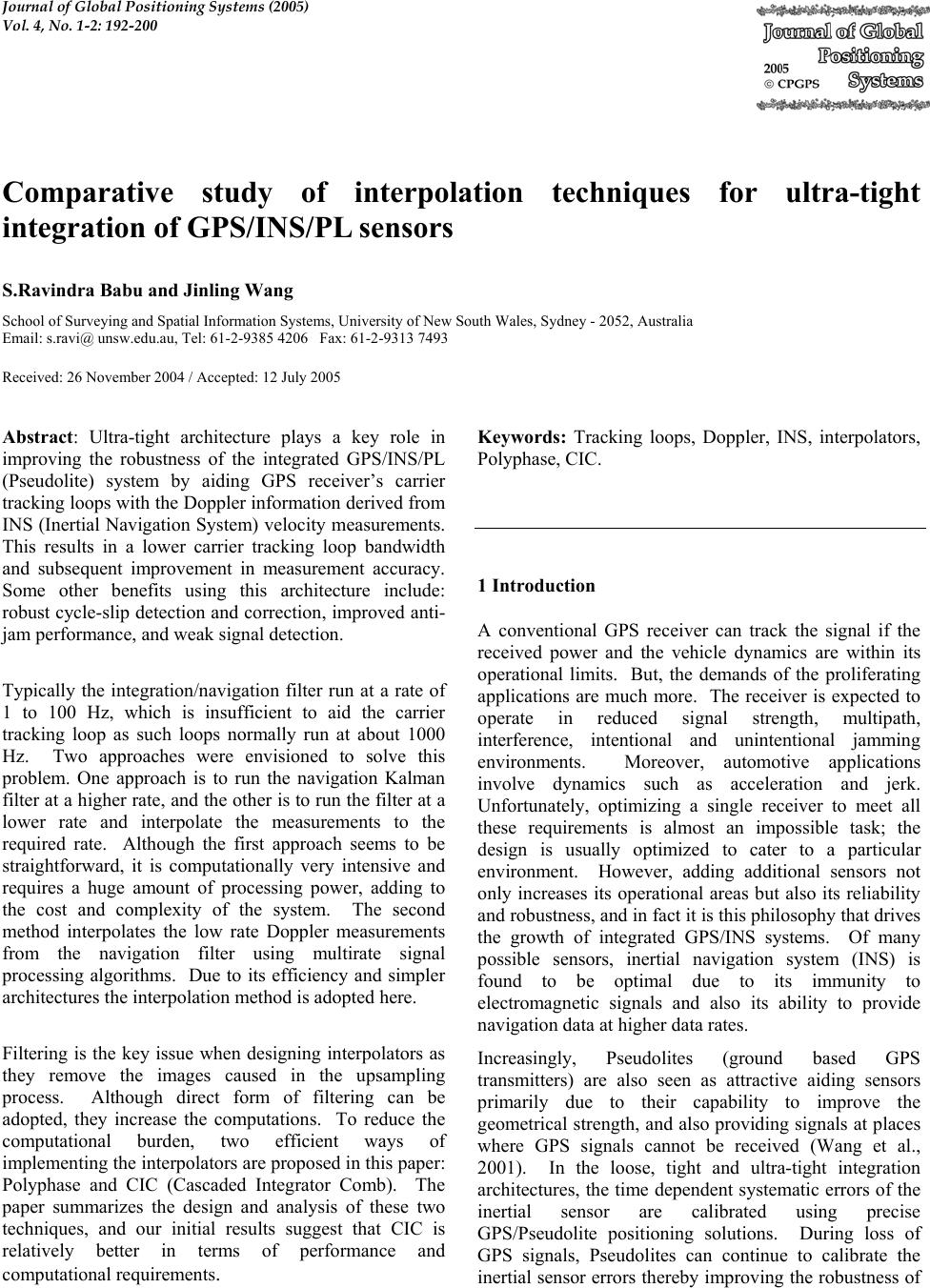 Journal of Global Positioning Systems (2005) Vol. 4, No. 1-2: 192-200 Comparative study of interpolation techniques for ultra-tight integration of GPS/INS/PL sensors S.Ravindra Babu and Jinling Wang School of Surveying and Spatial Information Sy s tem s, University of New South Wales, Sydney - 2052, Austral ia Email: s.ravi@ un sw.edu.au, Tel: 61-2-9385 4206 Fax: 61- 2-9313 7493 Received: 26 November 2004 / Accepted: 12 July 2005 Abstract: Ultra-tight architecture plays a key role in improving the robustness of the integrated GPS/INS/PL (Pseudolite) system by aiding GPS receiver’s carrier tracking loops with the Do ppler information d erived from INS (Inertial Navigation System) velocity measurements. This results in a lower carrier tracking loop bandwidth and subsequent improvement in measurement accuracy. Some other benefits using this architecture include: robust cycle-slip detection and correction, improved anti- jam performance, and weak signal detection. Typically the integration/navigation filter run at a rate of 1 to 100 Hz, which is insufficient to aid the carrier tracking loop as such loops normally run at about 1000 Hz. Two approaches were envisioned to solve this problem. One approach is to run the navigation Kalman filter at a higher rate, and the other is to run the filter at a lower rate and interpolate the measurements to the required rate. Although the first approach seems to be straightforward, it is computationally very intensive and requires a huge amount of processing power, adding to the cost and complexity of the system. The second method interpolates the low rate Doppler measurements from the navigation filter using multirate signal processing algorithms. Due to its efficiency and simpler architectures the interpolation method is adopted here. Filtering is the key issue when designing interpolators as they remove the images caused in the upsampling process. Although direct form of filtering can be adopted, they increase the computations. To reduce the computational burden, two efficient ways of implementing the interpolators are proposed in this paper: Polyphase and CIC (Cascaded Integrator Comb). The paper summarizes the design and analysis of these two techniques, and our initial results suggest that CIC is relatively better in terms of performance and computational requirements. Keywords: Tracking loops, Doppler, INS, interpolators, Polyphase, CIC. 1 Introduction A conventional GPS receiver can track the signal if the received power and the vehicle dynamics are within its operational limits. But, the demands of the proliferating applications are much more. The receiver is expected to operate in reduced signal strength, multipath, interference, intentional and unintentional jamming environments. Moreover, automotive applications involve dynamics such as acceleration and jerk. Unfortunately, optimizing a single receiver to meet all these requirements is almost an impossible task; the design is usually optimized to cater to a particular environment. However, adding additional sensors not only increases its operational areas but also its reliability and robustness, and in fact it is this philosophy th at drives the growth of integrated GPS/INS systems. Of many possible sensors, inertial navigation system (INS) is found to be optimal due to its immunity to electromagnetic signals and also its ability to provide navigation data at highe r dat a rat es. Increasingly, Pseudolites (ground based GPS transmitters) are also seen as attractive aiding sensors primarily due to their capability to improve the geometrical strength, and also providing signals at places where GPS signals cannot be received (Wang et al., 2001). In the loose, tight and ultra-tight integration architectures, the time dependent systematic errors of the inertial sensor are calibrated using precise GPS/Pseudolite positioning solutions. During loss of GPS signals, Pseudolites can continue to calibrate the inertial sensor errors thereby improv ing the robustness of  Babu et al.: Comparative Study of Interpolation Techniques for ultra-tight integration of GPS/INS/PL 193 the integrated architecture. Therefore, for applications such as indoors, foliage etc., integrating Pseudolites with GPS and INS systems will certainly improve the performance especially in terms of robustness and reliability. The integrated GPS/INS/Pseudolite systems are not new in the field of navigation, and are being developed for nearly two decades; however, the architectures in which these two systems can be integrated have changed over the period of time. The principal idea behind these architectures is if GPS or a Pseudolite can calibrate inertial sensor errors during normal operation, then the calibrated INS can provide navigation during GPS outages. Traditionally, both these systems were integrated in the so called loosely coupled architecture, where the navigation solutions from both the systems were combined in an external Kalman filter to provide an optimal solution. Though the implementation of this system looks simple, nevertheless there are limitations in this type of architecture (Farrell, 2000). To overcome some of these shortcomings, tightly coupled architecture was developed where a GPS/Pseudolite receiver is not considered as a navigation system but as a sensor that provides pseudo-ranges (PR) and pseudo range-rates (PRR) which can be integ rated with INS variables. Some of the advantages of this system are: it can provide navigation even with one satellite though with a degradation, and lesser correlation of the integration variables (PR, PRR) reduces the complexity of the integration Kalman filter. The recent development in this series is the Ultra-tight integration, i.e. integration of I (in-phase) and Q (quadrature) variables from the receiver’s tracking loops with INS. The inherent property of this system is the integration of INS derived Doppler feedback to the carrier tracking loops. This forms an important advantage of this system, as the INS Doppler aiding removes the vehicle Doppler from the GPS/Pseudolite signal, it facilitates a significant reduction in the carrier tracking loop bandwidth (Babu & Wang, 2004); on a comparative scale the dynamics on the pseudorandom noise code is very less due to its low frequency nature. The bandwidth reduction improves the anti-jamming performance of the receiver, and also increases the post correlated signal strength. In addition, due to lower bandwidths, the accuracy of the raw measurements is also increased. But, the INS aiding of th e receiver tracking loops require higher Doppler update rates from INS. As the update rate of the tracking loops is normally about 1 KHz, the derived Doppler rates should be generated at the same rate for the aiding to be efficient. One possible method is to run the Kalman filter at a high rate, i.e. 1000 Hz; however, this requires an extensive processing power. The second method is to generate Doppler at lower rates and then interpolate to the required rate (Beser et al., 2000; Gardner, 1993). This is the method adopted in this paper. The Kalman filter from which the Doppler is generated typically runs at 1 or 100 Hz, and the Doppler measurement is then interpolated by a factor of 10 or 100 for aiding. An increase in sampling rate can be accomplished by using interpolators which can efficiently be designed using multi-rate signal processing techniques (Mitra, 1999; Crochiere & Rabiner, 1983). A lowpass FIR (finite impulse response) filter is used in the interpolators to remove the images caused in the upsampling process. The filter transfer function is efficiently realized using Polyphase and CIC (Cascaded integrator comb) techniques (Hentschel, T., & Fettweis, 1990). While the polyphase method involves decomposing the filter transfer function into parallel stages, CIC implements the interpolator transfer function without using multipliers. This paper discusses on the design issues of both these techniques with their advantages and disadvantages. 2 Doppler estimates from INS The GPS/Pseudolite receiver computes its velocity by measuring the Doppler offsets on the GPS and Pseudolite signals. Therefore, measuring the Doppler signal accurately becomes imperative. After down converting the L1 signals to IF (intermediate frequency), the acquisition loops co arsely measures the carrier frequ ency and code offsets, and then pass these coarse measurements to the tracking loops for fine tracking. Due to their low loop bandwidths (typically about 12 to 18 Hz), the tracking loops are sensitive to the Doppler changes, whereas acquisition loops with a Doppler bin size of about 500 Hz are almost insensitive except in circumstances of very high dynamics. This places severe constraints on the tracking loops. For tracking high dynamics (acceleration and jerk), the bandwidth should be greater than 18 Hz with the order of the loop increased to 3Hz (Kaplan, 1996); however, this affects the quality of measurements and stability of the loop. The received Doppler from satellites and Pseudolites are given as _(1 ) rel rx gpstxva ffc =− G (1) where tx fis the transmitted GPS/Pseudolite L1 frequency (1575.42 MHz), rtrel vvv −= is the relative velocity between satellite and receiver, a G is the line of sight vector, and cis the velocity of light. The total Doppler on the received signal is due to the satellite and receiver motion, and satellite and receiver clock biases as shown in equation (2). 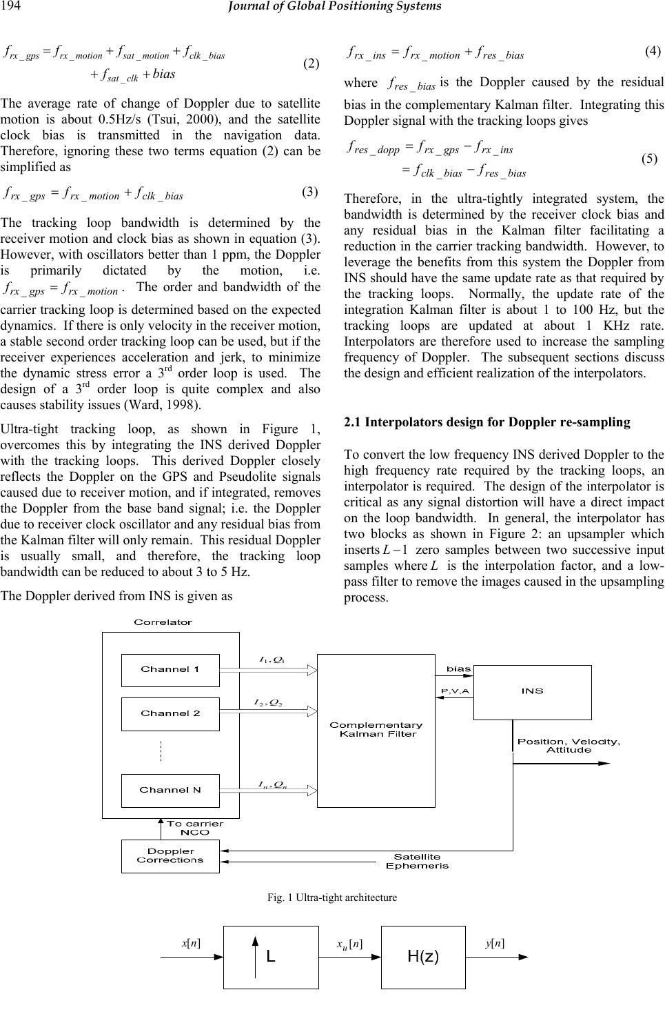 194 Journal of Global Positioning Systems __ _ _ _ rx gpsrx motionsat motionclk bias sat clk ff ff fbias =+ + ++ (2) The average rate of change of Doppler due to satellite motion is about 0.5Hz/s (Tsui, 2000), and the satellite clock bias is transmitted in the navigation data. Therefore, ignoring these two terms equation (2) can be simplified as biasclkmotionrxgpsrx fff ___ += (3) The tracking loop bandwidth is determined by the receiver motion and clock bias as shown in equation (3). However, with oscillators better than 1 ppm, the Doppler is primarily dictated by the motion, i.e. motionrxgpsrx ff __=. The order and bandwidth of the carrier tracking loop is dete rmined based on the expected dynamics. If there is only velocity in the receiver motion, a stable second order tracking loop can be used, but if the receiver experiences acceleration and jerk, to minimize the dynamic stress error a 3rd order loop is used. The design of a 3rd order loop is quite complex and also causes stability issues (Ward, 1998). Ultra-tight tracking loop, as shown in Figure 1, overcomes this by integrating the INS derived Doppler with the tracking loops. This derived Doppler closely reflects the Doppler on the GPS and Pseudolite signals caused due to receiver motion, and if integrated, removes the Doppler from the base band signal; i.e. the Doppler due to receiver clock oscillator and any residual bias from the Kalman filter will only remain. This resid ual Dop pler is usually small, and therefore, the tracking loop bandwidth can be reduced to about 3 to 5 Hz. The Doppler derived from INS is given as biasresmotionrxinsrxfff ___ += (4) where biasres f_is the Doppler caused by the residual bias in the complementary Kalman filter. Integratin g this Doppler signal with the tracking loops gives biasresbiasclk insrxgpsrxdoppres ff fff __ ___ −= − = (5) Therefore, in the ultra-tightly integrated system, the bandwidth is determined by the receiver clock bias and any residual bias in the Kalman filter facilitating a reduction in the carrier tracking bandwidth. However, to leverage the benefits from this system the Doppler from INS should have the same update rate as that requ ired by the tracking loops. Normally, the update rate of the integration Kalman filter is about 1 to 100 Hz, but the tracking loops are updated at about 1 KHz rate. Interpolators are therefore used to increase the sampling frequency of Doppler. The subsequent sections discuss the design and efficient realization of the interpolators. 2.1 Interpolators design for Doppler re-sampling To convert the low frequen cy INS derived Doppler to the high frequency rate required by the tracking loops, an interpolator is required. The design of the interpolator is critical as any signal distortion will have a direct impact on the loop bandwidth. In general, the interpolator has two blocks as shown in Figure 2: an upsampler which inserts 1 − L zero samples between two successive input samples whereL is the interpolation factor, and a low- pass filter to remove the images caused in the upsampling process. Fig. 1 Ultra-tight architecture 11,QI 22 ,QI nn QI, ][nx u ][nx ][ny 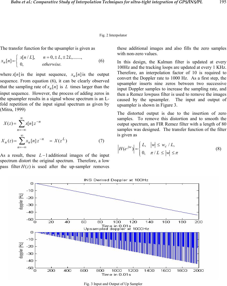 Babu et al.: Comparative Study of Interpolation Techniques for ultra-tight integration of GPS/INS/PL 195 Fig. 2 Interpolator The transfer function fo r the upsampler is given as ⎩ ⎨ ⎧±±= =.,0 ,.......,2,,0],/[ ][ otherwise LLnLnx nxu (6) where ][nx is the input sequence, ][nxuis the output sequence. From equation (6), it can be clearly observed that the sampling rate of][nxu is L times larger than the input sequence. Ho wever, the process of adding zeros in the upsampler results in a signal whose spectrum is an L- fold repetition of the input signal spectrum as given by (Mitra, 199 9) n n znxzX − ∞ −∞= ∑ =][)( )(][)( L n n uu zXznxzX== ∑ ∞ −∞= − (7) As a result, these 1−Ladditional images of the input spectrum distort the original spectrum. Therefore, a low pass filter)(zH is used after the up-sampler removes these additional images and also fills the zero samples with non-ze ro values. In this design, the Kalman filter is updated at every 100Hz and the tracking loops are updated at every 1 KHz. Therefore, an interpolation factor of 10 is required to convert the Doppler rate to 1000 Hz. As a first step, the upsampler inserts nine zeros between two successive input Doppler samples to increase the sampling rate, and then a Remez lowpass filter is used to remove the images caused by the upsampler. The input and output of upsampler is shown in Figure 3. The distorted output is due to the insertion of zero samples. To remove this distortion and to smooth the output spectrum, an FIR Remez filter with a length of 80 samples was designed. The transfer function of the filter is given as ⎪ ⎩ ⎪ ⎨ ⎧ ≤≤ ≤ = ππ wL LwwL eH c jw /,0 ,/, )( (8) Fig. 3 Input and Output of Up Sampler  196 Journal of Global Positioning Systems Fig. 4 Impulse and Frequency response of Remez filter To preserve the signal shape, the pass-band edge should be atLww cp /=, where c wis the highest frequency in the input spectrum. The impulse and the frequency response of the Remez filter is shown in Figure 4. The up sampled Doppler is then filtered to remove the images. The output of the filter shown in Figure 5 has almost the same shape as the original Doppler but with an increase in number of samples. Fig. 5 Interpolated Doppler Although the FIR filter has a linear phase, it is computationally inten sive. Therefore, efficient structures such as Polyphase and CIC based techniques can be adopted to realize the low pass transfer function )(zH which is the focus of the subsequent sections. 2.2 Polyphase Decomposition Efficient realization of the interpolation filter)(zH in equation (8) can be obtained using polyphase decomposition technique (Vaidyanathan, 1990). It is a method by which the original transfer function can be divided into L different branches given by ∑ − = − = 1 0 )()( L k L k kzHzzH (9) where .1..,.........1,0][][)( −=+==∑∑ ∞ −∞= ∞ −∞= −− LkzkLnxznxzH nn nn kk (10) The subsequences ][nxkare called the polyphase components of the parent sequence][nx , and the functions )(zHk, given by the z-transform of {} ][nxk, are called the polyphase components of)(zH . The transfer function given in equation (10) can be realized using Type II Polyphase decomposition as shown in Figure 6. Note that in Figure 6, the input of the polyphase filters run at the low sampling rates f, while the output sampling frequency is s fL , the increase is due to the generation of L samples from the parallel stages; i.e. for a single input sample there are ten output samples. The original impulse response of length 80 is split into 10 stages with each stage having 8 samples as shown in Figure 7. The relationship between the original FIR filter ][nh with a length M and the polyphase filters ][nHk is given as 1...............,2,1,0 1................,2,1,0)(][ −= −=+= Kn LknLkhnHk (11) 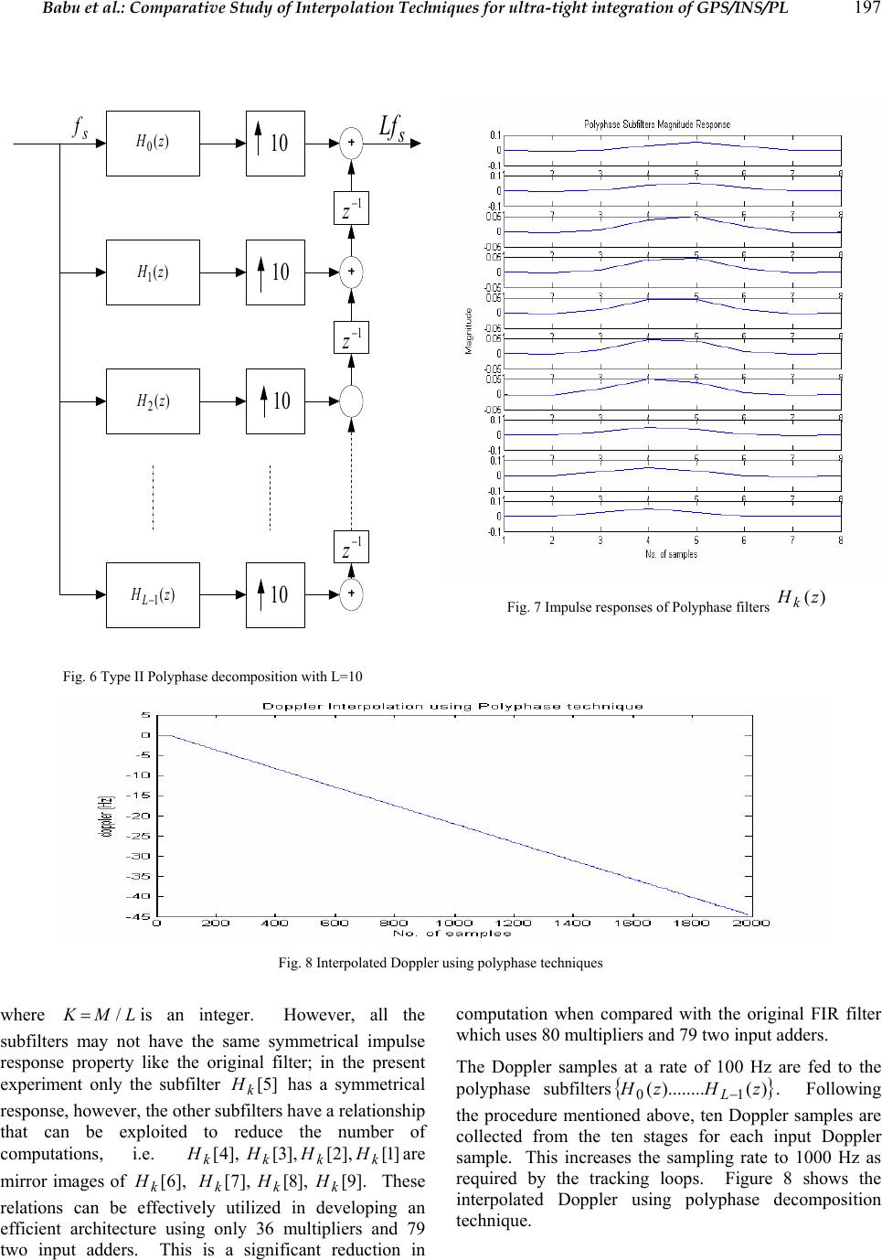 Babu et al.: Comparative Study of Interpolation Techniques for ultra-tight integration of GPS/INS/PL 197 Fig. 6 Type II Polyphase decomposition with L=10 Fig. 7 Impulse responses of Polyphase filters )(zHk Fig. 8 Interpolated Doppler using polyphase techniques where LMK/=is an integer. However, all the subfilters may not have the same symmetrical impulse response property like the original filter; in the present experiment only the subfilter ]5[ k H has a symmetrical response, however, the other subfilters have a relationship that can be exploited to reduce the number of computations, i.e. ]1[],2[],3[],4[ kkkkHHHH are mirror images of ],6[ k H],7[ k H],8[ k H].9[ k H These relations can be effectively utilized in developing an efficient architecture using only 36 multipliers and 79 two input adders. This is a significant reduction in computation when compared with the original FIR filter which uses 80 multipliers and 79 two input adders. The Doppler samples at a rate of 100 Hz are fed to the polyphase subfilters { } )()........( 10zHzH L−. Following the procedure mentioned above, ten Doppler samples are collected from the ten stages for each input Doppler sample. This increases the sampling rate to 1000 Hz as required by the tracking loops. Figure 8 shows the interpolated Doppler using polyphase decomposition technique. )( 0 zH 10 )( 1 zH 10 )( 2 zH 10 )( 1 zH L− 10 1− z 1− z 1− z s Lf s f 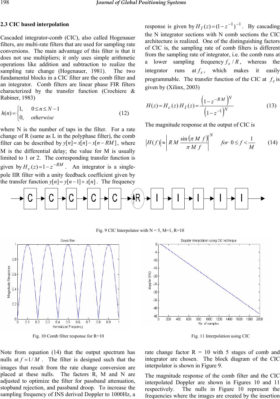 198 Journal of Global Positioning Systems 2.3 CIC based interpolation Cascaded integrator-comb (CIC), also called Hogenauer filters, are multi-rate filters that are used for sampling rate conversions. The main advantage of this filter is that it does not use multipliers; it only uses simple arithmetic operations like addition and subtraction to realize the sampling rate change (Hogenauer, 1981). The two fundamental blocks in a CIC filter are the comb filter and an integrator. Comb filters are linear phase FIR filters characterized by the transfer function (Crochiere & Rabiner, 198 3) ⎩ ⎨ ⎧−≤≤ =otherwise Nn nh ,0 10,1 )( (12) where N is the number of taps in the filter. For a rate change of R (same as L in the polyphase filter), the comb filter can be described by][][][ RMnxnxny −− = , where M is the differential delay; the value for M is usually limited to 1 or 2. The corresponding transfer function is given byRM czzH − −=1)( . An integrator is a single- pole IIR filter with a unity feedback coefficient given by the transfer function][]1[][ nxnyny + − =. The frequency response is given by11)1()( −− −= zzHI. By cascading the N integrator sections with N comb sections the CIC architecture is realized. One of the distinguishing factors of CIC is, the sampling rate of comb filters is different from the sampling rate of integrator, i.e. the co mb runs at a lower sampling frequencyRfs/, whereas the integrator runs ats f, which makes it easily programmable. The transfer function of the CIC at s fis given by (Xilinx, 2003) ( ) () N N MR Ic z z zHzHzH 1 1 1 )()()( − − − − == (13) The magnitude response at the output of CIC is () M ffor fM fM MRfH N1 0 sin )( <≤≈ π π (14) Fig. 9 CIC Interpolator with N = 5 , M=1, R=10 Fig. 10 Comb filter response for R=10 Fig. 11 Interpolation using CIC Note from equation (14) that the output spectrum has nulls atMf /1=. The filter is designed such that the images that result from the rate change conversion are placed at these nulls. The factors R, M and N are adjusted to optimize the filter for passband attenuation, stopband rejection, and passband droop. To increase the sampling frequency of INS derived Doppler to 1000Hz, a rate change factor R = 10 with 5 stages of comb and integrator are chosen. The block diagram of the CIC interpolator is shown in Figure 9. The magnitude response of the comb filter and the CIC interpolated Doppler are shown in Figures 10 and 11 respectively. The nulls in Figure 10 represent the frequencies where the images are created by the insertion 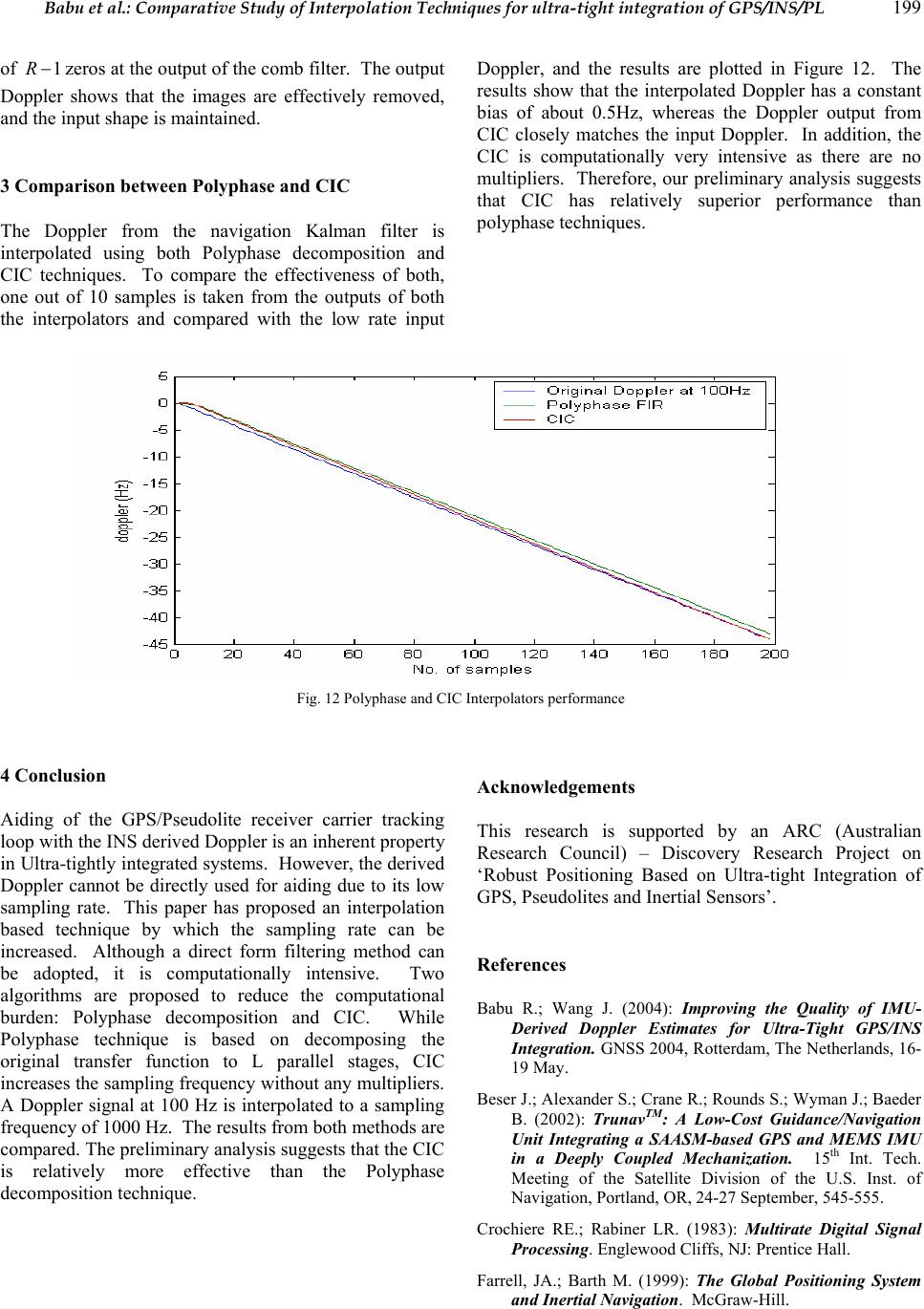 Babu et al.: Comparative Study of Interpolation Techniques for ultra-tight integration of GPS/INS/PL 199 of 1−Rzeros at the output of the comb filter. The output Doppler shows that the images are effectively removed, and the input shape is maintai ned. 3 Comparison between Polyphase and CIC The Doppler from the navigation Kalman filter is interpolated using both Polyphase decomposition and CIC techniques. To compare the effectiveness of both, one out of 10 samples is taken from the outputs of both the interpolators and compared with the low rate input Doppler, and the results are plotted in Figure 12. The results show that the interpolated Doppler has a constant bias of about 0.5Hz, whereas the Doppler output from CIC closely matches the input Doppler. In addition, the CIC is computationally very intensive as there are no multipliers. Therefore, our preliminary analysis suggests that CIC has relatively superior performance than polyphase techniques. Fig. 12 Polyphase and CIC Interpolators performance 4 Conclusion Aiding of the GPS/Pseudolite receiver carrier tracking loop with the INS derived Doppler is an inherent property in Ultra-tightly integrated systems. However, the derived Doppler cannot be directly used for aiding due to its low sampling rate. This paper has proposed an interpolation based technique by which the sampling rate can be increased. Although a direct form filtering method can be adopted, it is computationally intensive. Two algorithms are proposed to reduce the computational burden: Polyphase decomposition and CIC. While Polyphase technique is based on decomposing the original transfer function to L parallel stages, CIC increases the sampling frequency without any multipliers. A Doppler signal at 100 Hz is interpolated to a sampling frequency of 1000 Hz. The results from both methods are compared. The preliminary analysis suggests that the CIC is relatively more effective than the Polyphase decomposition technique. Acknowledgements This research is supported by an ARC (Australian Research Council) – Discovery Research Project on ‘Robust Positioning Based on Ultra-tight Integration of GPS, Pseudolites and Inertial Sensors’. References Babu R.; Wang J. (2004): Improving the Quality of IMU- Derived Doppler Estimates for Ultra-Tight GPS/INS Integration. GNSS 2004, Rotterdam, The Netherlands, 16- 19 May. Beser J.; Alexander S.; Crane R.; Rounds S.; Wyman J.; Baeder B. (2002): TrunavTM: A Low-Cost Guidance/Navigation Unit Integrating a SAASM-based GPS and MEMS IMU in a Deeply Coupled Mechanization. 15 th Int. Tech. Meeting of the Satellite Division of the U.S. Inst. of Navigation, Portland, OR, 24-27 September, 545- 555. Crochiere RE.; Rabiner LR. (1983): Multirate Digital Signal Processing. Englewood Cliffs, NJ: Prentice Hall. Farrell, JA.; Barth M. (1999): The Global Positioning System and Inertial Navigation. McGraw-Hill.  200 Journal of Global Positioning Systems Gardner FM. (1993): Interpolation in Digital Modems – Part I: Fundamentals. IEEE Transactions on Communications, COM-41(3), 501-507. Hentschel T.; Fettweis G. (2000): Sample Rate Conversion for Software Radio. IEEE Communications Magazine, August, 2-10. Hogenauer EB. (1981): An Economical Class of Digital Filters for Decimation and Interpolation. IEEE Transactions on Acoustics, Speech and Signal Processing, Vol. ASSP-29, 155-162. Kaplan ED. (1996): Understanding GPS: Principles and Applications. Artech House, MA. Mitra SK. (1999): Digital Signal Processing – A Computer Based Approach. Tata McGraw-Hill Edition, India, ISBN 0-07-463723-1. Tsui JBY. (2000): Fundamentals of Global Positioning Receivers – A Software Approach. John Wiley & Sons, Inc. Vaidyanathan PP. (1990): Multirate Digital Filter, Filter Banks, Polyphase Networks, and Applications: A Tutorial. Proc. IEEE, 78, 56-93. Vesma J. (1999): Optimizations and Applications of Polynomial-Based Interpolation Filters. PhD Thesis, Tempere University of Technology, Finland, ISBN 952- 15-0206-1. Wang J.; Dai L.; Tsuiji T.; Rizos C.; Grejner-Brzezinska D.; Toth C. (2001): GPS/INS/Pseudolite Integration: Concepts, Simulation and Testing. 14th Int. Tech. Meeting of the Satellite Division of the U.S. Inst. of Navigation, Salt Lake City, Ohio, 11-14 September, 2708- 2715. Ward P. (1998): Performance Comparisons Between FLL, PLL and a Novel FLL-Assisted PLL Carrier Tracking Loop Under RF Interference Conditions. 11th Int. Tech. Meeting of the Satellite Division of the U.S. Inst. of Navigation, Nashville, Tennessee, 15-18 September, 783- 795. Xilinx. (2003): Digital Up Converter (DUC) DS276 v1.0 Product Specification. (http://www.xilinx.com/ipcenter/catalog/logicore/docs/duc. pdf). |