Open Journal of Applied Sciences
Vol.4 No.7(2014), Article
ID:46861,7
pages
DOI:10.4236/ojapps.2014.47037
Experimental Evidence of Capillary Interruption of a Liquid Jet
Taha Massalha1, Rafael M. Digilov2
1Academic Arab College for Education, Haifa, Israel
2Department of Education in Technology & Science, Technion-Israel Institute of Technology, Haifa, Israel
Email: tahamas@gmail.com, edurafi@technion.ac.il
Copyright © 2014 by authors and Scientific Research Publishing Inc.
This work is licensed under the Creative Commons Attribution International License (CC BY).
http://creativecommons.org/licenses/by/4.0/


Received 23 April 2014; revised 26 May 2014; accepted 3 June 2014
Abstract
We observe the gravity discharge of liquid through the short cylindrical tube of diameter of 2 mm and aspect ratio 2.5 and 10 attached to the underside of Mariotte bottle. When the hydrostatic head is reduced and approaches to a certain value, a laminar jet escaped from the nozzle is interrupted and the discharge is drop wise. The plot of the discharge rate as a function of hydrostatic head does not pass through the origin as predicted by Torricelli law for an ideal liquid. We attribute this feature to the energy losses related with creating a new free surface area of the jet. The measurements for water and aqueous ethanol solution are compared with theoretical predictions based on the modified Bernoulli equation with the interfacial energy density correction and good agreement is observed.
Keywords:Mariotte Bottle, Modified Bernoulli Equation, Interfacial Energy Density Correction

1. Introduction
The simplest example of the use of Bernoulli’s equation in introductory physics course [1] is Torricelli’s law, which relates the velocity of efflux of a liquid issuing from the small orifice in a tank  to the hydrostatic head
  of the liquid:
 (1)
(1)
where  is the acceleration due to gravity. This result was recently questioned [2] [3] in the light of experimental evidence that at any nonzero
  the average discharge velocity is zero. The reason is that Bernoulli’s equation, which is a macroscopic mechanical balance of energy of an ideal, non-viscous liquid, cannot strictly be applied in the case of real flow due to the various dissipation effects [4] [5] , which Equation (1) does not include. Nevertheless, taking into account the energy losses, Bernoulli’s equation was used [3] to modified Equation (1) as follows:
 (2)
(2)
where  and
and  are empirical constants related, respectively, with the losses due to the losses proportional to the fluid velocity squared and the losses independent of the fluid velocity. While the presence of the constant
  in Equation (2) is somehow justified, there is no physical explanation for the constant
 . The interpretation proposed in [6] associates
  with capillary pressure, which hold up the liquid from coming out of the hole.
To give further understanding to this problem, we use the Bernoulli equation modified by the surface energy density and viscosity effect [5] to explain the physical meaning of the correction term . The validity of this approach is demonstrated by measuring the discharge velocity of Newtonian liquids with different surface tension and viscosity using discharge tubes of different aspect ratio.
2. Theoretical Background
Consider a Newtonian liquid of density , viscosity
  and surface tension
  discharged under gravity through the short tube of radius
  and length
  attached at the side of a large tank. A volume flux from the tube generates the axisymmetrical cylindrical jet of radius
 . We apply the modified Bernoulli equation [5] with the interfacial energy density along the streamline as is schematically shown in Figure 1:
 (3)
(3)
where  is the mechanical pressure,
  is the velocity at any point,
  is the height of the liquid above a reference level, all measured at the same point inside the liquid. The term
  represents the interfacial energy density required to create a unit of free surface area of the jet, and
  is the pressure head loss along the streamline due to various dissipative effects.
Let us apply Equation (3) for two points 1 and 2 of Figure 1, i.e. at the free liquid surface in the vessel and inside the jet. Since ,
,  ,
,  and
and , we get
 (4)
(4)
The derivative  in Equation (4) consists of two components, one being tangential and the other normal to the jet surface:
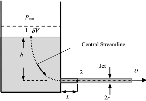
Figure 1. Schematic illustration of the discharge of Newtonian liquid from the tank.
 (5)
(5)
For an ideal cylindrical jet of length , volume
  and surface area
 , we have:
  and
and , where
  is due to formation of a fluid-air interface and
  due to its curvature. The physical meaning of these two effects can be clarified by considering the corresponding values of free energies. Whereas
  is the interfacial surface energy, the value
  gives
gives , the excess free energy due to the pressure jump across the interface. These two effects have to be considered together, therefore we have
 . However, since the shape of the jet is not a perfect cylinder, we introduce in this expression the shape factor
  to get
 (6)
(6)
Dissipation term  can be expressed [7] -[10] as the sum of the head loss at orifice entry of the tube and losses due to the skin friction within the tube orifice:
 (7)
(7)
Here,  is the coefficient of entry pressure loss, and
  is the skin friction coefficient, which depends on Reynolds number
  as
as
 (8)
(8)
where  and
and  are constants.
Combining Equation (4) with Equations (6) - (8), we obtain the sought equation for the average discharge velocity as a function of the pressure head:
 (9)
(9)
where constants  and
and  are typically,
  and
and  for laminar flow,
  and
and  for turbulent flow [10] . For laminar flow, Equation (9) reduces to the quadratic equation for
  with the solution:
 (10)
(10)
which involves the effects of viscous resistance and surface tension showing that at  the discharge velocity approaches to zero. We refer to this phenomenon as capillary interruption of a liquid jet. When the viscosity term
  becomes negligible, Equation (10) reduces to Equation (2):
 (11)
(11)
with . Equations (10) and (11) for the discharge velocity
  versus the pressure head
  of real liquids are the main result of present paper.
3. Experiment
To check the validity of the above theoretical approach we quantify the energy losses during the discharge of a real Newtonian fluid from the Mariotte bottle [11] -[13] (see Figure 2). We design a Mariotte bottle from the

Figure 2. Experimental set up for the measuring the discharge rate as a function of the pressure head υ(h).
plastic cylinder of diameter 78 mm and height 40 cm with the opening in the lower part of the wall. Plexiglas’s flange with O-ring at the top of the cylinder provides a seal.
An air intake tube of diameter 8 mm and length 50 cm was inserted through the flange using a compression fitting that seals with an o-ring. Glass capillary tubes with  and different lengths were separated inserted in the opening of the cylinder. As a liquid flows out of the bottle it is replaced by air, which enters through the air intake tube and bubbles up through the liquid level to provide a constant flow. The head, equal to the vertical distance from the bottom of the air-inlet tube to the outlet tube, was varied by raising or lowering the inserted tube. The discharge speed of liquid versus the pressure head was determined as follows. The force sensor, connected through a data logger to a computer, continuously recorded the fluid weight
  escaped from the bottle as a function of time. The average discharge velocity was calculated from the slope
  as
as
 (12)
(12)
Then, using the nonlinear curve fitting procedure available in MATHEMATICA (see Ref. 24 in [5] ), Equation (10) was fitted to measured discharge rate versus the pressure head  taking
  and
and  to be fitting parameters.
4. Results
To clarify the influence of surface tension and viscosity on the discharge rate of real liquids we used ordinary tap water with a density of , viscosity
  and surface
 , and also 30% aqueous ethanol of density
 , viscosity
  and surface tension
 . Two tubes of diameter 2 mm and aspect ratio
 and 10 were separate inserts in the opening of Mariotte bottle. To determine the effusion velocity
  versus the pressure head,
  , the liquid of the bottle was poured out into a plastic capacity mounted on the force sensor with the precision of 0.005 N, so that the measurement error over three trial experiments didn’t exceed 1%. Typical results of the discharge rate
  versus the pressure head
  are shown in Figure 3 and Figure 4 for two test liquids discharged through
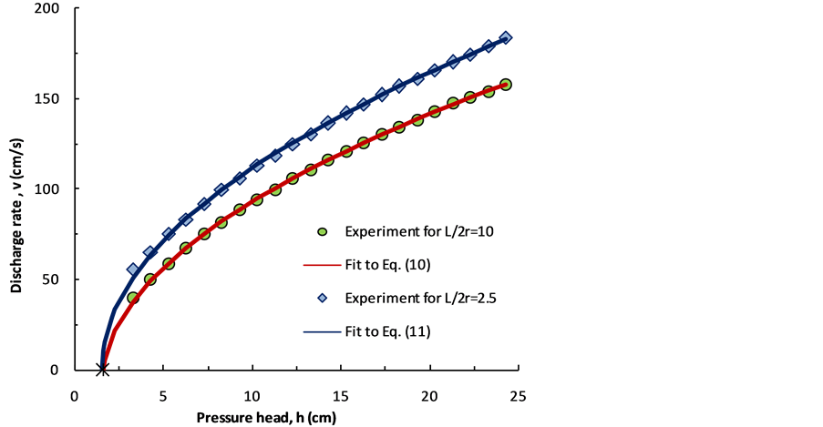
Figure 3. Discharge rate υ versus the pressure head h of tap water. Symbols denote experimental results. Solid lines are predicted by the present theory.
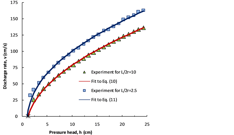
Figure 4. Discharge rate υ versus pressure head h of aqueous ethanol. Symbols denote experimental results. Solid lines are predicted by the present theory.
glass tubes with aspect ration  and 10 at temperature
 . It is seen that the discharge rate strongly depends on the fluid properties and the geometry of the outlet orifice. The range of the average discharge velocity,
  , Reynolds number, Re and fitting parameters k and b are presented in Table1
As expected, in the case of the discharge through the tube with  the viscous resistance plays a prominent role and the rate of discharge as function of the pressure head is better described by Equation (10), whereas Equation (11) provides the best fitting of experimental data
  of the same liquids discharged

through the orifice with , despite the fact that initially, in the case of water, the Reynolds number was slightly higher than its limit value 3000 for the laminar flow.
It can be seen also from Figure 3 and Figure 4, that over the range of the pressure head under operation, the rate of discharge of both liquids through the orifice with the aspect ratio  is considerably less than the rate discharge through the orifice with
 , as attributed to the viscosity resistance. If the point
 , at which the rate of the discharge
  decays to zero, is added to Figure 3 and Figure 4, it can be seen that the fit is quite reasonable. That the plot of
  in Figure 3 and Figure 4, intersects the horizontal axis at the same point
  for each liquid independently of the tube aspect ratio,
  , is indeed related to the fact that fluid flow losses energy in creating the free surface area of the jet as predicted by the theoretical model.
5. Summary
Subject of the discharge of Newtonian liquids from the container through the orifice of small diameter is an interesting topic in science education. One of the most important aspects that students can learn from these studies is the concepts of capillary pressure, interfacial energy and viscous. The use of the modified Bernoulli equation for the liquid jet, involving the interfacial energy density, is very useful for teaching the fundamentals of fluid flow. Students have the opportunity to study the effect of surface tension and viscosity on the fluid flow.
Acknowledgements
This work was partially supported by the Israel Ministry of Absorption and Immigration through the KAMEA Science Foundation.
References
- Halliday, D., Resnick, R. and Walker, J. (1977) Fundamentals of Physics Extended. 5th Edition, Wiley, New York.
- de Oliveira, P.M.C., Delfino, A., Costa, E.V. and Leite, C.A.F. (2000) Pin-Hole Water Flow from Cylindrical Bottles. Physics Education, 35, 110-119. http://dx.doi.org/10.1088/0031-9120/35/2/306
- Saleta, M.E., Tobia, D. and Salvador, G. (2005) Experimental Study of Bernoulli’s Equation with Losses. American Journal of Physics, 73, 598-602. http://dx.doi.org/10.1119/1.1858486
- Synolakis, C.E. and Badeer, H.S. (1989) On Combining the Bernoulli and Poiseuille Equation—A Plea to Authors of College Physics Texts. American Journal of Physics, 57, 1013-1019. http://dx.doi.org/10.1119/1.15812
- Massalha, T. and Digilov, R.M. (2013) The Shape Function of a Free-Falling Laminar Jet: Making Use of Bernoulli’s Equation. American Journal of Physics, 81, 733-737. http://dx.doi.org/10.1119/1.4819196
- Escamilla, P.L.L. (2009) Surface Tension Influence in Vessel Discharge: Comment on Experimental Study of Bernoulli’s Equation with Losses by Saleta M. E., D. Tobia and G. Salvador Gil [Am J Phys 73 (7), 598-602 (2005)]. American Journal of Physics, 77, 477-478. http://dx.doi.org/10.1119/1.3000362
- Fox, R.W. and McDonald, A.T. (1973) Introduction to Fluid Dynamics. Wiley New, York.
- White, F.M. (1979) Fluid Mechanics. McGraw-Hill, New-York.
- Streeter, V.L. and Wylie, E.B. (1986) Fluid Mechanics. McGraw-Hill, New-York.
- Ramamurthi, K. and Nandakumar, K. (1999) Characteristics of Flow through Small Sharp-Edge Cylindrical Orifices. Flow Measurement and Instrumentation, 10, 133-143. http://dx.doi.org/10.1016/S0955-5986(99)00005-9
- Schwertz, F.A. (1950) Rate-Indicating Mariotte Bottle. Analytical Chemistry, 22, 1214-1216. http://dx.doi.org/10.1021/ac60045a043
- Maroto, J.A. and de Dios, J. (2002) Use of a Mariotte Bottle for the Experimental Study of the Transition from Laminar to Turbulent Flow. American Journal of Physics, 70, 698-701. http://dx.doi.org/10.1119/1.1469038
- Kires, M. (2006) Mariotte Bottle with Side Openings. The Physics Teacher, 44, 388-389. http://dx.doi.org/10.1119/1.2336147