Design of 2D-Bootlace Lens with Five Focal Feed for Multiple Beam Forming ()
1. Introduction
In many radar and communication applications, it is often required to scan a wide area using an antenna array. A multiple beam-forming network is required to control the amplitude and phase at each element of the antenna array. Microwave bootlace lens forms an important class of multiple beam forming networks. Ruze [1] suggested a lens for wide-angle scanning. Rotman and Turner [2,3] suggested modification in Ruze’s lens to improve the scanning capabilities. Wide-angle scanning capabilities of these lenses are well established [4-6]. P. K. Singhal et al. [7] suggested modified design equations to improve the performance of the bootlace lens.
Bootlace lenses have traditionally offered great design flexibility without the excessive cost and reliability difficulties of phased array. This present report proposes to improve the current lens technology by developing a five focal point lens with scanning capability in a plane. As with previously developed multifocal bootlace lenses, specifying several adjacent perfectly focused scanned beam gives a well-focused field of view across the region bounded by the focal points. The entire aperture is used for all beams, providing optimum efficiency for this antenna.
2. Lens Design
Figure 1 shows the geometry of five focal point bootlace lenses. For a lens with five perfect focal points, the focal points are positioned as two pairs in different scan planes
and one central point. Un-scanned focus to accommodate a wide, two-dimensional field of view [8].
Using the design approach suggested in [9] and modified for this design following equations are written:
 (1)
(1)
 (2)
(2)
 (3)
(3)
 (4)
(4)
 (5)
(5)
where
 (6)
(6)
 (7)
(7)
 (8)
(8)
 (9)
(9)
 (10)
(10)
The five path length equation (counting each choice of ‘±’ as a single equation) are now simplified and solved numerically to give the surface and transmissions line length F = Distance from F1 to O & F2 to O called the off-axis focal length.
G = Distance from F0 to O called the on-axis focal length.
N = Indicate the position of the radiating elements, called the lens aperture.
er = Substrate dielectric constant.
ere = Effective dielectric constant of the transmission lines.
Design parameters are normalized relative to the maximum lens aperture Nmax and defined as follows:
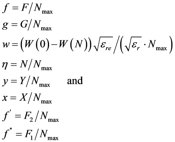
Algebraic manipulation of the equations above gives
 (11)
(11)
 (12)
(12)
 (13)
(13)
 (14)
(14)
 (15)
(15)
Normalized by Nmax
 (16)
(16)
 (17)
(17)
 (18)
(18)
 (19)
(19)
 (20)
(20)
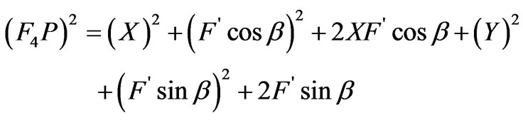
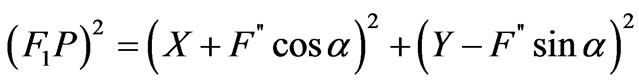
Now by the equations (1-5)
 (21)
(21)
 (22)
(22)
 (23)
(23)
 (24)
(24)
 (25)
(25)
Squaring (21) to (25)
 (26)
(26)
 (27)
(27)
 (28)
(28)
 (29)
(29)
 (30)
(30)
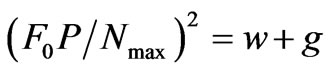
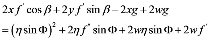
Equating both  by equation (25), (30)
 (31)
(31)
Equating both (16) & (26), (17) & (27), (18) & (28), (19) & (29) and putting the value of  by equation (31)
 (32)
(32)
 (33)
(33)
 (34)
(34)
 (35)
(35)
Add (32) & (34), (33) & (35)
 (36)
(36)
 (37)
(37)
Sub. (32) & (33), (34) & (35)
 (38)
(38)
 (39)
(39)
By (38) & (39)
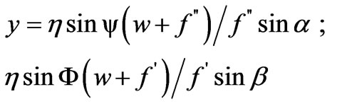 (40)
(40)
By (36) & (37)
 (41)
(41)
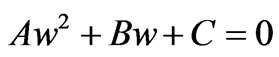
Value of x & y put into equation (31) and solve then we get the equation
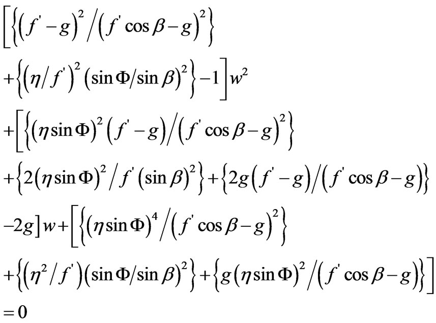 (42)
(42)
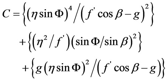
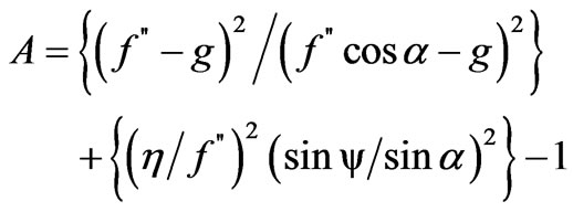
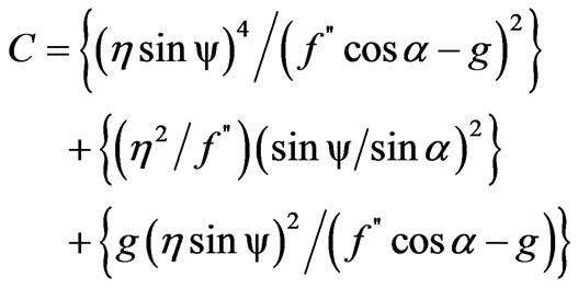
Compare
 (43)
(43)
where


Again Value of x & y put into equation (40) and solve then we get the equation
 (44)
(44)
Compare
 (45)
(45)
where

3. Simulated Result
Based on design equations the proposed design has been simulated for the following parametric values:

and the f3 and f4 are opposite to the f1 and f2. The results shown below in figure 2 it is clearly shown that the beam width has been reduced drastically and will provide further power spectral efficiency and better scanning area with less amount of power, thus reducing the effective cost of the equipment used for interfacing antenna array.

Figure 2. Simulated result of five feed bootlace lens.
4. Conclusion
Design equation of 2D-Bootlace lens with five focal feed for multiple beam forming has been computed and proposed geometry has been simulated using MATLAB, which gives result as per prediction of this design and will yield wave-front as per specification.
5. Acknowledgements
Authors would like to acknowledge the financial support of Dept. of Science and Technology, Govt. of India and the authorities of Madhav Institute of Technology & Science, Gwalior, India.