1. Introduction
The head is part of the body most threatened by the fatal injuries in accidents. Brain injuries cause approximately 56,000 dead and 83,000 disabled in the United States each year [1]. The typical duration of loading in road accidents is between 1 ms and 50 ms, according to the rigidity of the impacted area. This interval is approximately between 20 Hz and 1000 Hz frequency. It is therefore essential to carry out measures to the Interior of this frequency band. Because of the impossibility of technical and legal studies of human in vivo, they have been supplanted by studies in vitro performed in low proportion on humans [2-4], and largely on animals like pigs [5-8] and monkey [9-11].
The aim of this work is to develop a model to simulate the variation of the impedance mechanical (Z = force/ speed) material cerebral pork (viscoelastic materials [12]) on a range of frequency from 60 Hz to 580 Hz. The studied material is assumed to be homogeneous, isotropic, and stationary.
2. Method
The sample mixture of substances grey and white taken within the cerebral cortex pig brain is cylindrical, diameter d = 2 cm, height h = 3 mm and mass M = 1 g. It is cut from using part takes precedence. It entails part allows cutting cylindrical samples by helical motion descent. This is a method commonly used in [13] soft tissue Biomechanics because it allows you to obtain a cylindrical geometry, uniaxial tests, allowing the hypothesis of a field of uniform and unidirectional constraint depending on the axis of the cylinder. The sample is requested at its bottom surface with a sinusoidal force F = F0exp(j2πft) provided by a vibrating pot where the sample is deposited. The vibration solicitation is therefore a normal tension/compression type solicitation. This solicitation is own weight of the sample. A sensor force brought into contact with the vibrant plateau of the pot enables measurement of the force F applied to the underside of the sample. The speed v of top sample is measured by a speed sensor to laser. Treatment of experimental data by software MATLAB allows us to deduce the F0 force as well as speed v0 module.
2.1. Experimental Device
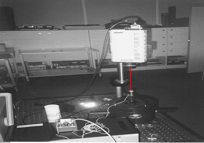
The experimental device (Figure 1) mainly includes a vibrant pot, a force sensor, a laser (helium neon) speed sensor and a computer with its acquisition Board (HPVEE). Note that experience was carried out ten times with samples taken from the same region (cerebral cortex), different, of the same dimensions.
2.2. Modeling of the Mechanical Impedance
To determine the theoretical mechanical impedance Zth = F/v of studied system, we have associated the mechanical model to 5 channels (types Kelvin-Voigt) (Figure 2) that we used in 2009 [14] to characterize brain matter of pork in terms of modulus of elasticity and depreciation internal. The vibration of the sample is then equated with the vibration of 5 overlapping cylindrical layers on the other. Each layer is then height h5 = h/5 diameter d and mass m5 = M/5.
To resolve the problem we have used the analogy of
 (a)
(a) (b)
(b)
Figure 1. (a) The experimental device; (b) Diagram of the experimental device.
mechanical/electrical (analogy force—voltage). Thus, our mechanical model was replaced by an electric model (Figure 3) with resistors R5, inductances L5 and capacitors C5:
In this circuit V0 and V5 represent the voltage input and output circuit respectively. I0 and I5 are input and output circuit intensities. Since then, studied mechanical system is excited a single endpoint (lower surface) that the

Figure 3. Electrical model analogous to our KV mechanical model.
other end (upper surface) is free (is not subject to any constraints), in this case, in our electric model output should be short-circuitée (V5 = 0). On this circuit transfer matrix is given by:
 (1)
(1)
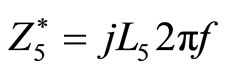
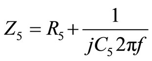
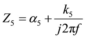
where  and
and  are the equivalent impedances to the inductance and the resistance in series with the capacity respectively:
 (2)
(2)
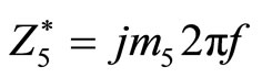
and
 (3)
(3)
Allowing us to write:
 (4)
(4)
with 
It follows that

The two Equations (5) and (6) allows us to deduce that
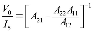 (7)
(7)
By returning to our mechanical model (KV model) and taking into account the analogy mechanical/electrical, theoretical expression of the mechanical impedance Zth = F/v can then be written as (7). Except that (2) and (3) and electrical impedance will be replaced by their mechanical analogues:
and

Figure 4. Superposition theory/experience of mechanical impedance modulus.
2.3. Determination of the Parameters of the Model
By introducing the k5(f) values and α5(f) already calculated in 2009 (Table 1) [14] we could calculate the values from the MATLAB software, and corresponding to each frequency of vibration of the sample. The module on KV model to 5 mass layers depending on the frequency theoretical mechanical impedance variation is then determined.
3. Results
The next curve represents the theory/experience the mechanical impedance module overlay.
From the Figure 4 we can see that the values of k5(f) and α5(f) already determined in 2009 [14], model very well the mechanical impedance of the studied system.
4. Conclusions
Our model (5-layer mass) type Kelvin-Voigt, with variable parameters based on the frequency is very well to simulate changes in mechanical impedance module of cylindrical sample of pork brain tissue.
The theoretical mechanical impedance Zth = F/v, that was used in this study, can be used in finite element model of brain to simulate the mechanical impedance.
This mechanical impedance represents a maximum in the surrounding of 400 Hz. It means that deformation is maximal at this frequency.
So, we can note that this frequency vibration can cause damage on the brain tissue.
NOTES