Received 2 March 2016; accepted 2016

1. Introduction
As the demand for intelligent vision-based human and computer/machine interfaces continues to grow, more intuitive and cost-efficient alternatives to conventional human-machine interfaces such as mice, keyboards, and touch-screens are required. Examples of such interfaces are vision-based hand gesture recognition system and handwriting recognition systems [1] - [3] . In sign language recognition, hand gestures are interpreted as symbols and words. On-line handwriting recognition systems provide a natural, convenient, and touch-free interface for human-computer interaction. This opens the door to new wireless character-inputting methods. Human fingertip can be used as a pointer input interface in place of a pen or a mouse, making the interaction/interface more user- friendly. A fingertip writing recognition system has applications, such as virtual mouse, signature input device and application selector.
In general, a visual fingertip/handwriting recognition system consists of 3 modules: visual data acquisition, feature extraction, and handwriting recognition. Based on a user’s body position, 3D trajectories of the human body, arm and/or hand can be reconstructed [4] [5] . An easier way for human hand or fingertip movement detection is based on image segmentation methods, such as skin color segmentation, background subtraction, etc. [6] - [8] . The connecting vectors between sampled points of the trajectory serve as features for the handwriting recognition system. The key-features selected are trajectory points, tangent angles, curvatures, etc. [8] [9] . Commonly used handwriting recognition techniques include template matching, DTW (dynamic time wrap) based KNN classifiers, hidden Markov models (HMM), neural networks, etc. [5] [7] [9] [10] .
Most earlier handwriting or fingertip-writing character recognition interfaces are built on PC-based systems with image input from USB cameras or Microsoft Kinect RGB-D sensors. This work focuses on an entirely FPGA based implementation with input from a CMOS image sensor. The proposed system achieved recognition accuracy of 100% for digits and lower case alphabets, and it could deal with scaled finger motion. One requirement of the system is that a fingertip blue cover is mounted on the user’s finger and is visible to the camera.
2. Main Approach
2.1. System Overview
The proposed vision-based fingertip-writing character recognition system, as shown in Figure 1, is built on the Altera DE2-115 FPGA development board. A LCD display with a camera module (VEEK_MT) is connected to the DE2-115. A fingertip blue cover is mounted on the top of the user’s finger in order to simplify fingertip detection and to enhance the recognition accuracy. The main functional modules of this fingertip-writing character visual recognition system, as shown in Figure 2, consist of (1) fingertip detection, (2) fingertip tracking and recording, (3) character stroke feature angle extraction, and (4) template matching with a KNN classifier.
2.2. Character Stroke Feature Angles
For each fingertip stroke, 9 feature points are extracted. The stroke's starting point is denoted by , and the end point by
 . Another 6 curve feature points
 ,
,  , are then uniformly sampled along the stroke curve between start to end. The last feature point,
  , is the average point of the above 8 sampled points,
 (1)
(1)
Each stroke curve is encoded with 10 key feature angles, as shown in Figure 3. The first seven feature angles,  ,
,  , are tangent angles of vectors between consecutive sample points,
 (2)
(2)
![]()
Figure 1. A fingertip writing character recognition system setup.
![]()
Figure 2. Functional modules of the visual character recognition system: (1) fingertip detection, (2) fingertip tracking and recording, (3) character stroke feature angle extraction, and (4) template matching.
![]()
Figure 3. Illustration of a character stroke's 10 feature angles.
The function  is a four quadrant arctangent function, such that
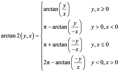 (3)
(3)
The last three features angles  are angles of the triangle consisting of the start point
![]() , end point
, end point ![]() and average point
and average point![]() , and are obtained using the cosine theorem,
, and are obtained using the cosine theorem,
![]() (4)
(4)
![]() (5)
(5)
and
![]() (6)
(6)
where ![]() are edge lengths of the triangle.
are edge lengths of the triangle.
2.2. Template Matching and Kth-Nearest-Neighbor Classifier
The proposed character recognition is based on template matching using a K-near-neighbor (KNN) classifier. Feature angles of reference characters (in the template i-th j-th feature angle table) are denoted by![]() ,
, ![]() ,
, ![]() , where i stand for the i-th character in the alphabet sequence of
, where i stand for the i-th character in the alphabet sequence of![]() , as shown in Appendix. The match distance between input stroke, encoded with feature angles
, as shown in Appendix. The match distance between input stroke, encoded with feature angles![]() , and each character template i is then computed by
, and each character template i is then computed by
![]() (7)
(7)
where
![]() (8)
(8)
Let ![]() denote the reference character satisfying
denote the reference character satisfying![]() , then the KNN classifier output is
, then the KNN classifier output is
![]() (9)
(9)
zero stands for an unknown character stroke.
3. Fingertip Detection and Tracking
The fingertip detection image processing module captures real-time images with a CMOS image sensor, image capture is followed by fingertip detection, character stroke tracking, and feature points recording. Figure 4 shows the functional block diagram of fingertip detection image processing module. The processing pipeline includes color space transformation, histogram equalization, color detection, filtering, object tracking and recording.
The RGB to YCbCr color transform is defined as
![]() (10)
(10)
where ![]() and
and![]() . Color space transform is followed by histogram equalization for the
. Color space transform is followed by histogram equalization for the ![]() component. Let histogram density function of
component. Let histogram density function of ![]() be denoted by
be denoted by
![]() (11)
(11)
where ![]() is the total number of pixels, then the histogram equalization function is
is the total number of pixels, then the histogram equalization function is
![]()
Figure 4. The image processing of fingertip detection and tracking.
![]() (12)
(12)
Then, the fingertip blue-cover color segmentation is performed as
![]() (13)
(13)
where ![]() denotes the
denotes the ![]() component after histogram equalization. Finally, a rank order filter in a
component after histogram equalization. Finally, a rank order filter in a ![]() window,
window,
![]() (14)
(14)
is applied twice to generate binary image, where pixels in the ![]() window are numbered from 1 to 25 from left to right and then top to bottom, with
window are numbered from 1 to 25 from left to right and then top to bottom, with ![]() being the center pixel. True pixels indicate potential fingertip positions. The detected fingertip position is recoded and tracked at a frequency of 7 times per seconds.
being the center pixel. True pixels indicate potential fingertip positions. The detected fingertip position is recoded and tracked at a frequency of 7 times per seconds.
4. FPGA Implementation and Experiment
The proposed fingertip-writing visual character recognition system is implemented as a dedicated logic circuit on a FPGA chip. Real-time image input is feed to the FPGA chip line by line. Up to 5 rows of a image are stored in line-buffers (FIFO) in a pipelined fashion. The image processing pixel clock is 96 MHz. The raw image data is captured by a color camera with ![]() resolution and a frame rate of 7 fps (frames per second). The raw image is converted to a
resolution and a frame rate of 7 fps (frames per second). The raw image is converted to a ![]() 24-bit RGB image (by a local neighborhood of every four scanned pixels). Figure 5 shows the image processing pipeline for fingertip detection and tracking.
24-bit RGB image (by a local neighborhood of every four scanned pixels). Figure 5 shows the image processing pipeline for fingertip detection and tracking.
Two mathematical functions, arccos(x) and arctan2(y,x), are required when computing a character stroke's feature angles. The arccosine function is implemented using a lookup-table with a resolution of 1.0 degrees. CORDIC algorithm [11] with 12-bit input data is applied to compute tangent angles. Figure 6 shows the pipelined CORDIC design for computing first-quadrant inverse tangent on the FPGA chip. The four-quadrant inverse tangent function can then be obtained from Equation (3). The synthesis results for all character recognition system architectures are shown in Table 1. The overall percentages of total FPGA resource are enclosed in parenthesis.
![]()
Figure 5. The image processing pipeline of fingertip detection and tracking.
![]()
Figure 6. Pipelined CORDIC design for computing first quadrant inverse tangent.
![]()
![]()
Table 1. Synthesis results and FPGA device utilization.
Figure 7 shows a typical fingertip detection and character recognition execution. The start of the fingertip writing process is triggered by moving the fingertip to a start button box shown on the LCD screen. The recognition system then starts to track and record a character stroke after 4 seconds. The end of a stroke is signaled by holding the fingertip stationary for 2 seconds. The recognition result is shown on the LCD screen thereafter. The entire process takes about a few seconds. Figure 8 shows a 2-character writing recognition experiment, in which the recognition of the second character starts right after the first character is recognized by 3 seconds.
The following character stroke pairs are similar and are more difficult to distinguish, hence the requirement for special distinction mechanisms.
(1) Digit 0 and alphabet o: digit 0 is written clock-wise, and alphabet o counter clock-wise.
(2) Digit 2 and alphabet z: alphabet z is written with an additional up-tick stroke.
(3) Digit 5 and alphabet s: alphabet s is written with a smoother curvature.
(4) Digit 9 and alphabet g: alphabet g is written with an additional up-tick stroke.
(5) Alphabets f and t: alphabet f is finished with an left-up tick stroke.
Figure 9 shows the experimental sample character strokes of digits 0 - 9 and lower case alphabets a - z. The
![]()
![]()
![]()
Figure 8. Experimental 2-character writing recognition.
![]()
Figure 9. Experimental 36 character strokes of 0 - 9 and a - z.
proposed system demonstrated 100% recognition accuracy in our experiments. We tested each sample character 10 times (a total of 360 character strokes), and no recognition error occurred.
5. Conclusion
We have presented a simple but effective vision-based fingertip writing character stroke recognition system. The proposed system is implemented on a single FPGA chip with input from a CMOS image sensor. The recognition system achieved accuracy 100% for digits and lower case alphabets, and it could deal with scaled finger motion. One additional requirement of the system is that a blue cover is mounted on the user’s fingertip and is visible to the camera. In future work, we would like to perform recognition of words with a few characters.
Acknowledgements
This work is supported by Taiwan Ministry of Science and Technology grants MOST-103-2221-E-011-101 and MOST 104-2221-E-011-035.
Appendix
![]()
Table 2. Template of character stroke feature angles.
NOTES
![]()
*Corresponding author.