The Use of Cortical Bone Wedges from the Mandibular Ramus “Wedge Technique”: For 3-Dimensional Bone Augmentation of the Atrophic Ridges. Technique Presentation and Report of Case Series ()
1. Introduction
Alveolar bone loss is a result of teeth extractions, periodontal disease, trauma, pathologic conditions, failed implants, and failed bone expansion procedures may provide poor bone quality in height, width, angulation and impaired intermaxillary relationships. Ridge augmentation may be considered in such cases to enhance placement of dental implants at a proper prosthetic position. Several augmentation methods and materials have been successfully used but much controversy still exists [1] - [10].
Autogenous bone grafts was still the gold standard due to their biological activities, their safety and their excellent incorporation in the recipient bed. Common extra donor sites such as the iliac crest, rib, tibia, and calvarium are commonly used and provide large quantities of bone. The main disadvantages of extraoral donor sites are: the need for hospitalization, general anesthesia, prolonged healing time, co-morbidities, and visible scars [11] - [17].
Different intraoral donors sites are widely used as bone blocks and or as particulate bone. The most typical intraoral donor sites are the chin and retromolar area [18] [19] [20] [21] [22]. They have different degrees of co-morbidities and complications [23] [24] [25] [26] [27].
Non autogenous bone grafts: allografts, xenografts, and synthetic bone are widely used either alone or in combinations [28] - [34]. They eliminate the potential complications that associated with the donor site, their availability is unlimited but typically lacks osteoinductive characteristics and osteoprogenitor cells to the recipient sites.
Autogenous bone graft healing goes through revascularization together with remodeling and substitution of the graft, which results in integration of the graft and the recipient bed [35]. There is a strong relationship between revascularization and osteogenesis inside and around the graft [36].
Revascularization of the bone graft begins when blood vessels sprouts grow and penetrate the bone block. They originate from two sources: 1) from the recipient bed, and 2) from the surrounding soft tissue. Hammack and Enneking in 1960 found that penetration of the blood vessels to the cortical graft occurred at the sixth day [37].
De marco et al. in 2005 reported the timing and the penetration rate of the blood vessels in the autogenic bone block in rats. New capillaries were migrated from the surface of the recipient bed and penetrated the graft to varying degree [38]. Graft fixation plays a key role at the corticocancellous bone grafts survival and also minimize the early graft volume loss and infections [4] [39] [40].
In this article I introduce a new bone augmentation method, the Wedge Technique (WT), as a biological approach that utilizes the main advantage of autogenic bone by transfer living cells, and the main advantage of the allogenic particulate graft as an unlimited quantities and availability. The way that this technique employs the autogenic bone block harvested from the mandibular ramus in combination of particulate allogenic bone substitute makes the limited amount of bone harvested from intraoral donor sites enough for large augmentations, and may enhance the revascularization of the thin bone blocks (the bone wedges).
2. Patients and Method
During a 6-years period (2009-2015), the wedge technique was used to augment different sites of atrophic ridges (Table 1), and (Diagram 1). The majority of the patients were referred by their surgeons due to different types and degrees of alveolar bone deficiencies, a lot of them were caused as a result of failed implants or failed previous bone augmentation attempts. Medically compromised patients such as patients with uncontrolled diabetes, history of bisphosphonates treatment, history of radiation therapy and heavy smokers were excluded from the study.
The patients that were treated with FWT, and were informed at admission about the diagnosis and the treatment alternatives. It was explained to all the potential patients how this treatment differed from familiar bone augmentation methods. Willing patients signed the consent form in which all the treatment sequence, possible complications, and post-surgical instructions were reported and explained. The patients underwent three-dimensional bone augmentation at least in one site in different arch regions to restore an atrophied alveolar ridge. The majority of the cases had: 1) at least two sites at one jaw or at the both jaws, and 2) the majority of the sites were at the posterior mandible. Indications for the use of wedge technique in the participants included, atrophic alveolar ridge with bone deficit that needs vertical, horizontal or combined vertical and horizontal bone augmentation.
The retromolar/ramus area was the donor site for the bone cortical wedges of this technique. Post-operative instructions include soft diet for six weeks, antibiotics for ten days, meticulous oral hygiene and any use of removable appliance was not allowed.
Follow up examinations were performed every 2 weeks. Four months after the operation, the recipient sites were evaluated clinically (to assess the contour and the volume of the augmented ridge), and radiographically (by computed tomography) to examine the bone gain and the new available bone to receive dental implants. The measurements of the bone gain were obtained from the multislice CBCT. The bone height and width were measured in each slice before and after the bone augmentation, and the obtained new bone was calculated. The calculation
![]()
Table 1. Patients, augmented sites, and the donor site.
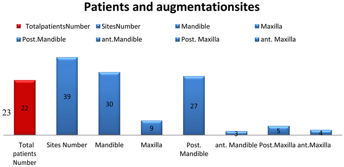
Diagram 1. Patients and augmented sites.
was made manually, that’s means the bone dimension after the surgery minus the initial bone dimension.
Reentry was performed after 4 to 5 months to evaluate the new bone volume, obtain biopsy specimens and insert implants. Patients were referred back to their dentists for prosthetic rehabilitation. Follow-up of the bone augmentations and implants that were inserted in these sites included periodic clinical evaluation and periapical radiographs. All the surgical procedures and postoperative evaluations were performed by the author.
2.1. Technique
Illustration case; 55 years old female was referred to pro-prosthetic unit at our department to augment her posterior mandible bilaterally in order to insert dental implants.
On examination; healthy patient with bilateral posterior mandibular edentulism (Kennedy class-1), lingually positioned and lingually angulated residual ridges (Figure 1(a)).
The computed tomography of her mandible demonstrated a moderate to severe atrophy of the both posterior mandibular ridges (Figure 1(b) and Figure 1(c)). Short implants are not option due to the severe lingual angulation of the ridges. Guided implants placement is not an optional treatment due to the central position of the inferior alveolar nerve. This case necessitated bone augmentation that was treated with the WT.
2.2. The Donor Site
Retromolar/ramus region is the gold standard of this technique. It can provide cortical bone block of 3 - 4 mm thickness, 2 - 3 cm length, 8 - 12 mm width, and its bone density is D1. At the present case the left retromolar area was the donor site.
Under general anesthesia, after IV administration 1 grm Augment in and 20 mg of Dexamethason, and local anesthesia with vasoconstrictor. A full-thickness mucoperiosteal flap was reflected with midcrestal incision distal to the second
![]()
Figure 1. WT, illustration case: Bilateral posterior mandibular edentulism. (a) and (b) Clinical view and panoramic view. (c) to (d) Computed Tomography shows inadequate bone in height, width, and angulation.
premolar. The incision was extended through the retromolar region to the ramus. An anterior oblique release incision was made at the first premolar and extended to the vestibular depth. This flap exposed the left augmented site (teeth 36 and 37 region), and the donor site of the bone block, It also allowed visualization of the lateral and inferior border of the mandible, the buccal shelf and the mental neurovascular bundle. The length (posterior-anterior) of the bone block, its width (superior-inferior) was determined and done by three complete osteotomies; posterior, anterior, and inferior (Figure 2(a)) with Micro Saw disc (Frios Micro Saw, DENTSPLY). The superior (crestal) edge was perforated with small holes by small round bur in a straight handpiece, and the determined the thickness of the bone block.
The block harvest was completed by straight osteotome that was malleated along the superior holes. The block was carefully released and obtained to avoid injury to inferior alveolar neurovascular bundle. The donor site was lifted to spontaneous healing.
2.3. The Wedge Preparation
The wedge preparation was done by multiple splitting of the harvested bone block. At the present case the bone block splitting was performed in its longitudinal axis, the firsts plit yielded two thinner bone blocks, and further splitting at the same axis gave 4 thin bone blocks from the original bone block (Figure 2(b) to Figure 2(d)). Further transverse splitting of the four thin bone blocks gave 8 - 10 thin bone blocks and each is one is called a bone wedge (Figure 2(e) and Figure 2(f)). In general we can make the splits of the original block at its transverse axis, and receive four thick bone blocks. Further splitting of those blocks at their long axis can give 8 - 10 thin bone wedges (Figure 2(g) to Figure 2(j)).
2.4. Recipient Site
The left recipient site was already exposed, the augmented bed is prepared by making grooves (slots, fissures) with high speed straight thin bur, low speed small straight bur or by piezo. In the present recipient site three bucco-lingual grooves were made (Figure 3(a) and Figure 3(b)). The numbers of the grooves are determined by the length of the augmented ridge, and the depth of the
![]()
Figure 2. WT, the donor site and the wedge preparation. (a) Bone block harvest from the left retromolar area. (b) to (f) Multiple splitting of the bone blocks result in multiple small bone wedges. (g) to (j) Transverse splitting of the harvested bone block maybe also done to create the bone wedges.
![]()
Figure 3. WT, The recipient site. (a) Grooves are created by height speed, low speed or piezoelectric. (b) Three grooves were created at the left side.
grooves is limited by its distance from the inferior alveolar nerve that can be measured on the dental CT scan. In general the groove should be through and through bucco-lingually, and as deep as possible. The role of the groove in this technique is retain biologically and mechanically the bone wedge.
2.5. The Augmentation Procedure
Try-in of the bone wedges into the grooves at the recipient bed, and adaptation of a bone wedge for each groove. Thereafter one adapted wedge is inserted and taped into one groove using flat edge cylindrical instrument and hummer (Figure 4(a)). It is extremely important to check the stability of each wedge by trying to extract it out from the groove. Unstable wedge should be removed and changed by a stable one. The next step is trimming of sharp edges of each wedge to prevent trauma to the soft tissue overlying the augmentation (Figure 4(b) and Figure 4(c)).
Multiple bone compartments are achieved from the above stages, (Figure 4(d)). The next step is the filling of those compartments with allograft bone substitute (Miner-0ss, BioHorizons) (Figure 4(e) and Figure 4(f)). The final product is the planned bone augmentation volume (Figure 4(g)), that subsequently was covered with resorbable collagen membrane (Geistlich Bio-Gide) (Figure 4(h)). The final step is tension free closure of the flap (Figure 4(i)). Free buccal fat pad graft may be used to enhance the closure of the flap.
Follow-up frequency was performed every two week for three months postoperatively (Figure 5(a) and Figure 5(b)). At 4 months after the operation, the patient was referred to CBCT dental to evaluate the amount of the bone gain from the augmentation procedure (Figure 5(c) to Figure 5(e)). The dental implants were inserted under local anesthesia (Figure 6). The patient was referred to her dentist for prosthetic rehabilitation 3 - 4 months after the implants surgery (Figure 7(a) to Figure 7(b)). This case was followed during 62 months (Figure 7(c) to Figure 7(e)).
![]()
Figure 4. WT, Bone augmentation. (a) Inserting and tapping of the wedges inside the grooves. (b) Trimming of sharp edges. (c) Checking the stability is crucial. (d) Bone compartments at the recipient site. (e) Bone filler allograft. (f) Filling the bone compartments with allograft particles. (g) The final bone volume. (h) Resorbable membrane. (o) Primary soft tissue closure.
3. Case Presentations
3.1. Case 1
A 45-year-old woman was referred to our department to augment atrophic ridges at the anterior and left posterior mandible.
On examination; partial edentulism of the mandible with missing anterior and
![]()
Figure 5. Follow-up 2 weeks. (a) Clinical view; (b) The panoramic view demonstrates one donor site and two recipient site; (c) to (e) CBCT four months after the surgery, nice bone gain.
![]()
Figure 6. Reentry 4 months. Nice bone gain: (a) RT side; (b) LT side; (c) and (d) Implants placement.
![]()
Figure 7. Follow up. (a) and (b): Crowns rehabilitation; (c) to (e): Panoramic radiograph and clinical view 36 months after the surgery.
left posterior teeth (43 - 33 and 35, 36) teeth 34 and 44 were with poor prognosis (Figure 8(a) to Figure 8(c)). CBCT was performed and demonstrated the bone deficit in height and width at the anterior and left mandible. (Figure 8(d) and Figure 8(e)).
She was treated in two stages. At the first stage FWT was performed to augment the anterior and left mandibular region.
Under general anesthesia, the bone block was harvested from the left retromolar area (the same surgical site), the bone block was split to achieve multiple bone wedges (Figure 8(f) to Figure 8(i)). The recipient sites were prepared by creating grooves, and thereafter 7 bone wedges were inserted into the grooves in a stable position, and trimmed to smooth their sharp edges. Several bone compartments were achieved (Figure 8(j) to Figure 8(l)), and filled with particulate allograft bone substitute. A final bone volume was achieved (Figure 8(m)), and then covered with resorbable membrane (Figure 8(n)). The recipient sites were closed primarily and tension free (Figure 8(o)). Temporary bridge based on teeth 34 and 44 was performed. The healing process was uneventful during the follow up period.
Mandibular CBCT was performed after 4 months to evaluate the available bone for dental implants (Figure 8(p) to Figure 8(r))). The bone gain was 4 - 6 mm horizontally and vertically. The reentry was performed under local anesthesia, and revealed the new bone volume. The bone wedges were integrated into
![]()
![]()
Figure 8. Case 1. (a) to (e): Clinical and radiographic view. (f) to (i): Bone block harvest and preparation of the bone wedges. (j) to (o): FWT bone augmentation anterior and left mandible. (p) to (r): CBCT 4 months after bone grafting. (s) to (v): reentry and implants insertion 4 months after the augmentation surgery. (w): radiographic view-follow up. (x) to (y): Crowns Rehabilitation. (z): 48 months-follow-up.
the new bone mass (Figure 8(s)), and 6 implants were inserted (Figure 8(t) to Figure 8(u)). Immediate loading was performed over the anterior implants (Figure 8(v)).
All the inserted implants were successfully osseointegrated (Figure 8(w) and Figure 8(x)) and the final rehabilitation was performed after 3 months later (Figure 8(y)). This case was followed for 48 months (Figure 8(z)).
3.2. Case 2
A 28-year-old woman was referred because of sever atrophy of anterior maxillary region that was augmented unsuccessfully by her surgeon. Clinical and radiographical examinations revealed sever atrophy of the anterior maxillary ridge and pneumatization of the right maxillary sinus (Figures 9(a)-(e)), teeth 23, 14
![]()
![]()
Figure 9. (a) to (s) Case 2. (a) and (b) Clinical view-anterior maxilla. (c) to (e): CBCT anterior maxilla. (f) to (g): FWT bone augmentation. (h) to (k): Clinical and radiographic view-follow-up four months. (m): Reentry 4 months, nice bone volume. (n) and (p): The drilling for the implants was performed inside the bone wedges. (q): 4 implants were placed in the recipient site. (r) and (s): Clinical and radiographic view at 4 months after the reentry. (t) to (u): Temporary rehabilitation follow up, 6 months after implants insertion.
and 15 were with poor prognosis. She was treated in three stages. At the first stage, bone augmentation of the anterior maxilla with the wedge technique, extracion and socket preservation of tooth 15, and open sinus augmentation at the right maxillary sinus were performed under general anesthesia. The right mandibular retromolar area was the donor site for the bone block. Four cortical bone wedges were inserted at the grooves that were prepared at the recipient site (Figure 9(f)). Particulate allograft bone substitute was used as the bone filler between the bone wedges (Figures 9(h)-(i)). Teeth 14 and 23 were preserved to hold temporary acrylic bridge during the healing period.
Follow-up examinations at 2 weeks, and three months (Figure 9(h)) showed excellent recovery. At 4 months, computed tomography of the maxilla showed the new bone gain and the current available bone “width; 6 to 10 mm” for implant insertion (Figures 9(i)-(k)). At second stage, the intra-operative views showed a good alveolar ridge, and the bone wedges had an excellent integration in the new bone volume (Figure 9(m)). Figure 9(n) and Figure 9(p) illustrate the drilling through those wedges. Teeth 14 and 13 were extracted and particulate allograft bone substitute was used to preserve their sockets. At this stage 4 implants were placed at the anterior augmented region with immediate loading (Figures 9(q)-(s)).
At the third stage, additional 4 implants were placed; 3 at the right maxilla and one implant at the location of tooth 23. Four months later the patient was referred to her dentist for fixed prosthesis over the implants (Figures 9(t)-(u)).
4. Results
4.1. Clinical Outcomes
Bone augmentation with cortical bone wedges was performed in 39 sites in 22 patients (15 women, 7 men; mean age 47 years; range 19 to 67 years). The healing process was uneventful. The donor site for the bone block, the retromolar area, healed very well without significant complications. Extra oral edema was resolved during 7 to 14 days after the surgery. Although in ten patients a temporary post-operative lower lip hypoesthesia was noted, it was resolved completely after 3 months. No incidence of permanent sensory deficit was recorded. Spontaneous regeneration of the donor sites was observed during the follow-up period without filling with bone substitutes at the surgery time.
In 21 patients the recipient sites healed very well, and the bone augmentations were maintained without wound dehiscence. In one patient, partial breakdown of the wound occurred, and the majority of the augmented bone was lost; this patient had completed treatment with nerve transposition.
Four months after the augmentation surgery, in 21 patients, clinical evaluation of the recipient sites revealed new hard tissue volume and good ridge contour. The CBCTs showed that good bone volume was obtained, and the bone gain was 4 to 8 mm horizontally and 3 - 6 mm vertically (Table 2).
The second surgery that was performed for implant insertion revealed a new and good bone volume, with excellent integration of the bone wedges in the recipient site.
114 implants were inserted of adequate lengths “10 - 16 mm” and diameters “3.3 - 4.2 mm” (Table 2). Further follow-up of the augmentation sites and the implants revealed stable outcomes. The mean follow-up period was 32 months.
4.2. Histologic Findings
At the reentry stage for implant insertion, hard tissue specimens were taken from the wedge area for histologic evaluation (Figure 10(a) and Figure 10(b)).
![]()
Table 2. Results; the bone gain, and the inserted implants.
![]()
Figure 10. (a)-(c) Histological examination. (a) Clinical view, wedge biopsy. (b) CBCT view of the site of the wedge biopsy. (c) The microscopic view of the bone wedge was captured at 20× magnification, the wedge is obvious at the center of the figure.
The histologic specimen of the bone wedge revealed osteocytes inside the bone wedge, osteoblasts and osteoclast in its periphery (Figure 10(c)). Those findings may indicate the vitality and remodeling of the graft.
5. Discussion
Autogenous bone grafts have been used many years for ridge augmentation and still considered the gold standard. Intraoral donor sites, mandibular symphysis and ramus are widely used. Extraoral donor sites are also used, and they are combined with major disadvantages that include the morbidity of the donor site, the high treatment costs, and high resorption rates [11] - [17].
Retromolar/ramus area is used as donor site, and the majority of the bone block that obtained is a cortical bone. Pikos in 2005 stated that one donor site can provide adequate bone volume for three-tooth segment, and can augment 3 - 4 mm as horizontal or vertical bone augmentation [41].
If extensive bone graft is required for one or more sites in the same mouth, then it may be necessary first to harvest simultaneously bilaterally from the ramus area and from the symphysis, or it may be necessary to make multiple augmentation of the same site. Schwarts reported the use of multitier technique for such cases. In addition some surgeons may use extraoral donor sites for extensive or multiple sites augmentations [42].
Among the major concerns in the bone block augmentation, two are important. First, bone block dislodgment during the implants insertion [43] , and second, the presence of connective tissue layer between the block graft and the recipient bony site [44].
The present report describes the wedge technique as a novel bone augmentation method that can be useful for multiple site augmentations as horizontal or vertical bone augmentation or both.
The multiple splitting of one harvested block may give 12 to 16 thin cortical bone wedges (0.6 to 1 mm thickness for each wedge), and 3 to 4 wedges that are used in the recipient site can augment three-tooth segment. A simple calculation shows that one harvested bone block can augment 3 to 4 sites of three-tooth segment. The uses of cortical bone wedges that are inserted into the grooves at the recipient site create bone compartments that are filled with bone particles, usually allograft, are the basic concept of this technique. This combination in this way makes it possible to augment more than one site (usually 2 to 3 sites) from one harvested bone block.
The grooves that are prepared at the recipient site by the wedge have several functions that include: 1) mechanical retention of the cortical bone wedge so there is no need for fixation materials like screws, and in this way the hazards of hardware infection and expenses can be eliminated. 2) biological retention of the cortical bone wedge, and this is because the grooves are a kind of recipient site decortication, and the injury to the blood vessels can enhance angiogenesis and revascularization of the thin bone wedge in one hand, and in the other hand can accelerate the regional acceleratory phenomenon which have an important function in the healing of the operated organs. It is well documented in the relevant literature that the success of bone grafting procedures depends mainly on the amount of revascularization (quality and intensity).
De Marco et al. in 2005 reported that several vascular sprouts proliferated toward the graft by the third day, and were demonstrated at the graft periphery. Revascularization was more intense in the area near the perforation of the recipient bed. Those findings may explain the integration the thin bone wedges in the retention grooves at the recipient bed, and this may happened due to the wide openings of the blood vessels when preparing the grooves at the recipient bed. Upon the histologic examinations from the bone wedges that were performed 4 months after the augmentation: Osteocytes were visible inside the wedge and indicates its vitality. In addition the presence of osteoclasts and osteoblasts at the periphery of the wedge is an indicator of the graft remodeling.
In FWT, the cortical bone wedge also has several functions; first, the thin nature of the wedge “0.5 - 1 mm” make it more readily to be penetrated by the vascular sprouts that emerge from the grooves at the recipient bed, so the revascularization of the graft may be earlier and more intensive than a thick block. Second, the bone wedge acts as space maintainer for the new bone volume, and this achieved by the multiple bone compartments that created between the bone wedges. Third the bone wedges while they are inserted in the grooves, they tent the membrane, support the particulate bone filler, and inhibit deformation of the augmentation materials. Insertion of several bone wedges at the recipient site creates a site with increased number of bone walls that may accelerate the regeneration of the treated sites. The wedge-groove unit increases the bone to bone contact surface and can lead to the end point of fast wedge to groove integration. Successful grafting depends directly on close contact between the graft and vascularization tissue, and in fixation of the graft to the recipient bed [35] [39]. Those two principles are found in the wedge-groove unit.
The cortical bone wedge technique has several advantages which includes: 1) Two harvested bone blocks for multisite augmentation in both jaws. 2) No need for fixation materials (Screws, miniplates or titanium mesh). 3) No need for extra-oral donor sites. 4) Reducing complications and expenses.
The use of free fat graft is usually used with this technique for double layer and tension free closure of the recipient site [45].
6. Conclusion
The cortical bone wedge technique biological rational is to create multiple autogenic bone compartments that filled with allogenic bone particles. This combination can augment multiple sites with intraoral autogenous bone blocks, and reduce the need for extraoral donor site. The wedge-groove unit may enhance revascularization of the bone graft and improve the graft survival.
Acknowledgements
Thanks to Doctor Abu Subeh Abir for her technical support.
Conflict of Interest
Declare that there is no financial interest or any conflict of interest.
Abbreviations
Wedge Technique (WT)
Fares Wedge Technique (FWT)