The Performance of MANET Routing Protocols for Scalable Video Communication ()
1. Introduction
A mobile Ad-hoc network (MANET) consists of a number of nodes that play two roles: sending packets and forwarding received packets. A MANET has no infrastructure to support routing and network management. Therefore, nodes in MANETs are responsible for all the tasks needed in order to communicate including routing. The overall performance of data delivery in a MANET is directly affected by the routing protocol used.
Routing protocols in MANETs are classified into two main categories: reactive and proactive routing protocols [1]. With reactive routing protocols, routing information is created when needed (on-demand). A source node invokes the routing protocol to establish a path to a destination node. Once the path is established, data packets are transmitted through the established path, and the path stays valid until it is not needed. Examples of reactive routing protocols are: AODV and DSR.
On the other hand, with proactive routing protocols, each node maintains a routing table and advertises its routing information to its neighbors continuously to maintain up-to-date routing information. Examples of proactive routing protocol are OLSR and DestinationSequenced Distance Vector routing (DSDV).
Scalable Video Coding (SVC) is the extension of H.264 Advanced Video Coding (AVC) [2,3]. SVC supports the layered encoding of video streams. Layered encoding allows the decoding of video at different temporal, spacial, and SNR qualities. This means that receiver nodes can recover video according to their capabilities and needs without the need for re-encoding and sending several video streams with various qualities.
SVC encodes video into layers: a base layer and one or more enhancement layers. Decoding lower video layers allows the recovery of a low quality video, while decoding enhancement layer(s) enhance(s) the quality of recovered video [4].
In this paper, the performance of AODV [5], DSR [6] and OLSR [7] is evaluated when employed in forwarding scalable video contents in two different network scenarios. The purpose of the first scenario is to evaluate the impact of increasing the number of hops between the source and the destination on the quality of the recovered video at the destination. The second scenario evaluates the impact of the number of concurrent independent video streams (connections) in the network on the quality of the recovered video under each of the three routing protocols we consider.
The evaluation in this paper employs several simulation tools including NS2 [8] with a video evaluation framework [9,10]. The use of these tools enables us to encode a real video, packetize it, and transform it into a form that can be transmitted over a MANET in NS2. When the simulation finishes, a trace file of the packets collected at the receiver node(s) is created. This file is used to regenerate the video taking into consideration the losses and delay that occurred while forwarding the video packets. The generated video is then visually assessed. Furthermore, the PSNR of the video is calculated and presented as part of the results in this paper.
The major contributions of this paper are as follows:
• The performance of the considered routing protocols is highlighted under various network scenarios. Realistic network conditions in terms of node’s distribution and mobility are employed and the quality of video communication as well as other performance metrics is evaluated.
• The selection of the tools used in this paper allows for better evaluation. In particular, instead of only using the average delay and packet loss ratio as the metrics to assess the quality of the recovered video, we can now visually assess the recovered video as well as calculate the PSNR of the recovered video. This is important since as shown in the results, presenting the average delay and the delivery ratio independently is not enough to judge the quality of the recovered video.
The rest of the paper is organized as follows: in Section 2 the MANET routing protocols understudy (AODV, DSR, and OLSR) are reviewed. In Section 3 the performance of the selected routing protocols is evaluated under different network scenarios and the evaluation results are discussed. Finally, in Section 4 the paper is concluded.
2. MANET Routing Protocols
There are two categories of MANET routing protocols: reactive and proactive. Reactive routing protocols are on demand routing protocols where routes are established when needed. Nodes exchange routing messages once a path between source and destination is established. On the other hand, with proactive routing protocols nodes maintain routing information all the time whether there is/isn’t data to send. Nodes maintain routing tables and exchange routing messages continuously so that they are ready to forward data packets any time.
Next, an overview of three important MANET routing protocols is provided. Two reactive routing protocols (AODV and DSR) and a proactive routing protocol (OLSR) are explained briefly. The performance of each of these protocols is assessed later in the paper when employed in forwarding scalable video contents.
2.1. Ad-Hoc On Demand Distance Vector (AODV)
AODV is a distance-vector reactive routing protocol. Nodes do not maintain routing information that is not needed or used. On the other hand, each node maintains a routing table that contains recently used routing information. For each recently targeted destination, a node maintains a next hop to that destination in its routing table along with other control information.
Route request (RREQ), Route reply (RREP), and Route Error (RERR), are the AODV messages used to create and maintain routing information. RREQ is a broadcast message that is sent by the source node in order to discover a path.
Source node S with data packets to be sent to destination node D checks its cache for a next hop to reach D. In case there is a next hop to D, S starts sending data packets to D through the found next hop immediately. On the other hand, if there is no next hop to D, S broadcasts an RREQ packet to its neighbors. A neighboring node that receives RREQ creates a reverse path to S, through which it can reach S.
The neighboring node receiving RREQ checks its cache for a next hop to D. In case there is a next hop to D, the neighboring node replies to the source with a RREP message. However, if there is no next hop to D, the neighboring node re-broadcasts the RREQ to its neighbors. The same is performed at the neighboring nodes receiving the RREQ message until a neighboring node replies with routing information to the source using RREP message or the destination D replies to the source.
In case a node finds that a route through a neighboring node is not valid anymore, it sends RERR message to its neighbors who inform their neighbors about the detected error.
2.2. Dynamic Source Routing (DSR)
DSR is a reactive routing protocol where routing information is created and maintained when needed. DSR is a source routing protocol where the full route is listed in the header of the data packet. The list includes the sequence of intermediate nodes through which packets are going to be forwarded. Unlike AODV, nodes do not rely on routing information at other nodes to reach destination. The whole path to reach destination is included in the packet header and hence no routing tables are needed at forwarding nodes.
Route request and route reply are the DSR messages used to establish a path between source and destination. Route request is a broadcast message that is sent by the source node in order to discover a path.
Each node caches a list of recently discovered paths. Source node S with data packets to be sent to destination node D checks its cache for a path to D. If there is a path to D, S starts sending data packets to D through that path immediately. If there is no path to D, S broadcasts a route request packet to its neighbors. A neighboring node receiving the route request checks its cache for a path to D. If there is a path to D, it replies to the source with the path using route reply message. If there is no path, the neighboring node records its address in the route request message and re-broadcasts the message to its neighbors. The same is performed at the neighboring nodes receiving the route request message until a neighboring node replies with a path to D using route reply or the destination D replies. The route reply message has the route recorded in the received route request message.
In the route request message received by a replying node (an intermediate node with a cached path or the destination), the path from S to the replying node is recorded in the request message received. Replying node checks its cache for a path to the source. If there is a path, the replying node uses the cached path as a source route for the route reply message. Otherwise, the reverse of the recorded route received in the route request message is used.
2.3. Optimized Link State Routing (OLSR)
OLSR is a proactive routing protocol where routing information is established and maintained at each node. Nodes exchange routing information continuously to adapt to network changes.
OLSR is a link state routing protocol. This means that nodes exchange link state information. After receiving link state information, each node creates shortest paths to other nodes.
OLSR employs two types of messages: HELLO and Topology Control (TC) messages. HELLO message is used to discover connectivity among nodes. TC message is used to propagate topology information through the network.
To control the amount of flooding of routing information, Multi-Point Relay (MPR) nodes are selected. MPRs are nodes that perform flooding of routing information. MPR nodes are the only nodes that generate link state information. Link state information is used by nodes to calculate shortest paths to other nodes based on the minimum number of hops.
Nodes maintain routing tables continuously. A source node with data packets to be sent to a destination will find routing information in its routing table; it can start sending data packets to the next hop from the routing table immediately.
3. Performance Evaluation
In this section we evaluate the performance of AODV, DSR and OLSR routing protocols when used for forwarding scalable video in different network scenarios. The metrics of evaluation in the simulations are the number of control packets generated while forwarding video packets, the percent of packets correctly received at destination, the average packet delay (average time it takes a packet from transmission to reception). And finally the PSNR of video recovered at destination.
The first metric of performance evaluation is the number of control packets generated while forwarding sender data to the destination. Routing protocols generate control messages in order to establish routing paths and/or maintain routing information. The routing protocol that generates less amount of control information while forwarding data to destination is preferable since more bandwidth is utilized for data transfer rather than control messages transfer.
The second metric of evaluation is the number of packets correctly received by the destination. This metric reflects the reliability of the routing protocol in propagating and delivering sender data to the destination.
The third metric of performance evaluation is the average packet delay per video packet sent. This is the average delay it takes each video packet to arrive to the destination through the sequence of forwarding nodes on the path to destination. As the average delay increases, the risk of packet loss increases. Each video packet is required to be delivered within a specific time period. A video packet received after the time interval is useless (lost).
The fourth metric of evaluation is PSNR. This metric reflects the quality of the decoded video sequence at the destination relative to the original video sequence (sent by the sender). Losses and late delivery of video packets causes video frame losses. As a loss concealment technique, every lost video frame is substituted by the last correctly received video frame. In other words, in the place of a lost video frame, the last correctly decoded frame is placed. Losses degrade the PSNR of the decoded video.
Network Simulator 2 (NS2) is used with an extension that allows sending the packets of real video. MyEvalSVC provides an extension for NS2 to support sending and receiving the video traces [9]. The input video is encoded using Joint Scalable Video Model (JSVM) [11]. Moreover, Scalable Video coding streaming Evaluation Framework (SVEF) [10] is employed in the process of sending the video and assessing the performance of recovered video.
JSVM is used to encode the raw video (Foreman) at Common Intermediate Format (CIF) with image size 352 × 288 and 30 frames per second. Foreman video consists of 300 video frames. JSVM is used to generate a packet trace file that lists the packets of the encoded video along with their sizes and PSNR characteristics. SVEF is used to generate another trace file that assigns each packet the sequence number of the video frame from which the packet was extracted.
The trace file generated by SVEF is converted into a format compatible with the format of NS2 input. Using NS2, the network topology is specified. Sender and receiver nodes are selected according to the simulation scenario. NS2 video trace file is what will be sent from the sender. When the simulation finishes, NS2 output packet trace file is generated. The output packet trace file at receiver lists the video packets that have been received by the receiver node. From the output video trace file a packet trace file compatible with JSVM is reconstructed. The JSVM reconstructed trace file usually suffers from packet losses. Lost packets are the packets that were not received by receiver node. At the same time, packets that were received late are considered lost packets. A timeout period of one second is established at receiver node. Video packets received with delay greater than one second are regarded lost packets and are not used to decode the video at the receiver node.
Lost packets results in loss of video frames. SVEF supports video loss concealment. Each lost video frame is replaced by the last correctly received video frame. The output of SVEF concealment is an encoded video file with a number of video frames equals the number of video frames in the original input video. The concealed video stream is then decoded using JSVM. The decoded video stream can be played where the effect of loss can be seen. At the same time, JSVM is used to find the PSNR of the decoded video stream.
The performance of AODV, DSR and OLSR is evaluated in two network scenarios shown in Figures 1 and 2. In both scenarios node transmission radius is 250 m, 802.11 g is the underlying Mac layer protocol. Packet size is 1000 bytes.
In the first scenario (shown in Figure 1), the distance between two adjacent nodes is 200 m. Node N0 is the source node. The performance of AODV, DSR and OLSR is evaluated when each of the other 9 nodes (N1-N9) is the destination. In all simulation runs, N0 is the source node. At each simulation run, a different receiver is selected. In the first simulation run, N1 is the destination. In the second run, N2 is the destination, and so on. The goal of this scenario is to evaluate the performance of the three different routing protocols as the number of hops between the source and the destination increases.
Figure 3 shows the percentage of control packets generated while forwarding video packets from the source to the destination. The x-axis represents the number of hops that separate sender and receiver. The less number of control packets, the lower overhead and hence the better performance. As the number of hops between source and destination increases, the amount of control packets generated increases. It is clear from Figure 3 that OLSR produces the largest amount of control packets. This is expected since OLSR is a proactive routing protocol where routing message are exchanged continuously regardless of the data packets sent. Figure 3 shows that AODV generates more control packets than DSR. Also, it is shown in the figure that for each of the three protocols, as the number of hops between the source and destination increases, the number of generated control packets increases.
Figure 4 shows the percentage of packets decoded at receiver. As the number of hops between source and destination increases, the percentage of decoded packets decreases. It is clear from the figure that both DSR and AODV have almost the same performance in terms of delivering video packets to destination. On the other hand, OLSR does not perform as well.
Figure 5 shows the average delay per packet received at the destination. The lower the delay, the better the performance. Figure 4 shows that OLSR has the best performance in terms of average packet delay. At the same time AODV has better performance than DSR.
Also, it is noted in Figure 5 that there is a decrease in average packet delay values for hop counts three and seven from the delay values for hop counts two and six respectively. Such variation in delay values is expected due to the small number of packets received among

Figure 2. Example of simulation scenario 2 with four connections.

Figure 3. Percentage of control packets to data packets generated (×100%).

Figure 4. Percentage of packets received to packets sent (×100%).

Figure 5. Average delay per packet received in seconds.
which the average delay is calculated. In other words, due to the small percent of packets received (for hop counts greater than or equal three) the delay of each packet received can clearly affect the average delay per packet received.
Figure 6 shows the PSNR of the video decoded at the destination. It is clear that OLSR achieves the lowest PSNR at the receiver node. Even though OLSR performed better in terms of average delay per packet received (as shown in Figure 5), the PSNR achieved by OLSR is the lowest among the three routing protocols. OLSR achieves the lowest PSNR due to its worst performance in delivering packets (as shown in Figure 4).
In the second scenario of evaluation, 50 nodes are randomly distributed in a 500 m × 500 m area. Nodes move randomly in a speed that is less than or equals to 10 mps. Source as well as destination nodes are selected randomly. At each simulation run in this scenario, a different number of concurrent connections is established between source(s) and destination(s). Figure 2 shows an example of scenario 2 with four connections.
In the first experiment of scenario 2, there is only one connection established between a source (randomly selected) and a destination (randomly selected). That means, throughout the simulation period, only one connection is established between two nodes selected randomly. In the second experiment, two connections are established between two different source-destination pairs (randomly selected). In the third scenario, three connections are created between three source-destination pairs. In the fourth experiment, four connections are created between four source destination pairs. In all the experiments, there is a random number of intermediate nodes between each source-destination pairs. Through each connection, the video packet trace file is sent. As explained previously, the output is a packet trace file of the video packets received by the receiver node(s).
Figures 7 shows the percentage of control packets generated while forwarding video packets from the source to the destination. As the number of connections in the network increases, the number of control packets generated increases. It is clear from the figure that OLSR produces the largest amount of control packets. This is expected since OLSR is a proactive routing protocol where routing messages are exchanged continuously regardless of the data packets sent. Figure 7 shows that AODV and DSR have almost the same performance in terms of the control packets generated.
Figure 7 shows that the percentage of control packets is decreasing as the number of connections increases in OLSR. As the number of connections increases, the total number of video packets forwarded increases and hence the percentage of control packets to video packets decreases. For AODV and DSR, as the number of connections increases, the percentage of control packets slowly increases in almost the same fashion as the number of data packets increases. This is indicated by the almost constant behavior of DSR and AODV as shown in Figure 7.

Figure 7. Percentage of control packets to data packets generated (×100%).
Figure 7 leads us to the conclusion that OLSR becomes more feasible as data traffic increases. When data traffic increases, the percentage of control packet to data packets decreases (less overhead).
Figure 8 shows the percentage of packets decoded at receiver to packets sent. As the number of connections in the network increases, the percentage of decoded packets decreases. It is clear from the figure that DSR and AODV have close performance. On the other hand, OLSR has slightly lower performance than the other two protocols.
Figure 9 shows the average delay per packet received at the destination as a function of established connections. It is shown in the figure that OLSR has the best performance in terms of average packet delay. At the same time, AODV has better performance than DSR.
Figure 10 shows the average PSNR of the decoded video. It is clear that OLSR achieves the best PSNR. Even though OLSR performed worse in terms of the percentage of decoded packets (as shown in Figure 8), its performance in terms of PSNR is better. The better performance of OLSR in terms of PSNR is due to the lower
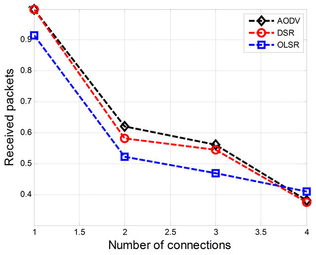
Figure 8. Percentage of packets received to packets sent (×100%).

Figure 9. Average delay per packet received in seconds.
delay per packet received achieved by OLSR (as shown in Figure 9).
In real-time applications like the communication of video, delay is very important. It is not enough of the routing protocol to be reliable, where data packets are delivered correctly but it is as important to deliver packets within an allowable delay limits. In case the delay exceeds limits, the received packets are useless and cannot be used in decoding video frames. This is the reason why OLSR achieved better PSNR even though smaller percentage of packets were received. With AODV and DSR, part of the packets received were received with higher delay values. These packets are useless and are discarded.
Since OLSR is a proactive routing protocol, routing information are established and maintained at nodes continuously (not on demand). In reactive routing protocols, routing information are established and maintained when needed (on demand). This explains the delay behavior of these protocols.
In Figure 10, PSNR achieved by OLSR is better when the number of connections is 2, 3 and 4. In the case of only one connection, the PSNR achieved by OLSR is slightly less than that achieved by AODV and DSR. This is because the three protocols achieve the same average delay per packet received (as shown in Figure 9). At the same time, OLSR achieves the lowest number of decoded packets among the three protocols (as shown in Figure 8).
4. Conclusions
In this paper we evaluated the performance of communicating scalable video over mobile Ad-hoc networks (MANET). AODV, DSR and OLSR are the three routing protocols evaluated. The performance was evaluated in two network scenarios. In the first scenario, the effect of increasing the number of hops between source and destination was assessed. Performance results showed that AODV and DSR achieve better performance than OLSR.
In the second scenario, a grid topology with mobile nodes randomly located was evaluated. The effect of increasing the number of connections over which video is streamed was assessed. Performance results showed that OLSR could achieve better performance in terms of video quality even though it achieves lower packet-delivery rates. The better performance in terms of video quality achieved by OLSR is due to the lower delays when forwarding video packets. OLSR is a proactive routing protocol where routing information is established and maintained continuously and not on demand as in the reactive routing protocols (AODV and DSR). This is the reason why OLSR achieves lower delays.