Modelling and Parameters Identification of Through-Hole Type Wind Turbine Contactless Sliprings ()
1. Introduction
Recently contactless slipring systems have gained high popularity among researchers for their several advantages as compared to conventional mechanical slipring systems. In a glance, the reliability and long life cycle, in combination with minimum maintenance requirement, are the main advantages of CSS (Contactless Slipring Systems). Use of conventional slipring assemblies is often undesirable, since their inherent high friction characteristics often cause excessive wear and increased maintenance [1]. The contactless slipring solution eliminates many of the disadvantages associated with the conventional systems [2,3].
However, with all the mentioned benefits, contactless slipring systems posed some unusual design constraints. To begin with, the relatively large gap in their magnetic circuit results in a low magnetizing inductance. Again, because of the air gap between primary and secondary windings results in high primary and secondary leakage inductances. Moreover, eddy currents, caused by fringing flux, can be formed in the magnetic material near the gap which could cause losses and local radiation [4]. Therefore, based on CSS features and the mentioned design restrains, having a reliable prediction and an accurate model of the contactless transformer used in such systems is essential for design prejudgments. Moreover, the obtained model is advantageous for theoretical calculations, electrical network simulations, and any further modifications before construction. This helps the designer to have a better understanding about the system and its associated limitations for any possible changes, in order to design the system so as to meet the application requirements. There are other methods such as testing /measurements and FEM analysis that can be used for design analysis. However, the measurement method can only be applied in practical systems and the finite element analysis is only suitable for preliminary calculations and simulations.
The aim of this paper is to obtain a complete procedure and derive the required equations for modeling two types of through-hole contactless transformers. Basic principle of a CSS is presented. This is followed by the effect of the fringing flux generated around the air gaps and the way of correcting this effect. Mathematical equations and developed theory are presented for obtaining the electrical model based on the physical layout. The reluctance equations are summarized for two contactless transformers for numerical calculations. Finite Elements Models are developed and simulation results are presented for the system assessment. A complete procedure of experimental contactless transformer measurements is presented. Two coaxial and face to face designs of a through-hole contactless transformer are prototyped and experimental testing are performed for modelling verification. Finally, to evaluate the theoretical modelling and calculations, a comparison with FEM and experimental results is conducted.
2. Basic Principle of Operation
Figure 1 shows two through-hole types (a) coaxial and (b) face to face structures of a contactless transformer. As it can be seen because of the air gap, the secondary can freely move or rotate relative to the primary. The block diagram of this system is demonstrated in Figure 1(c). The whole system includes primary converter, contactless transformer and secondary converter. Generally high frequency resonant converter is adopted at the primary to improve the power transfer characteristics. The secondary converter realizes rectifying and power converting according to the load requirements. A distance between the whole structure and the shaft is considered to avoid any excessive heating the shaft due to fringing flux lines, etc. The revolution of high-frequency switching power conversion allowed the magnetic link to be implemented with reasonably sized components [5]. This new technology creates new possibilities to supply portable devices with electrical energy which has been used in many different applications, each of them having particular specifications, necessities and restrictions.
The air gap is fixed for the first design, while it can be varied by moving the rotating part back and forth for the second design. Usually, for high power and small air gap situations, transformers with magnetic cores in primary and secondary side are appropriate. Other new coupling structures for a contactless transformer with single core and single air gap are proposed for this application [6,7]. In contrast, for large air gap and low power air transformers (coreless) are preferred. A special case is a sliding transformer which can have construction for linear or circular movement. The final configuration of contactless power transfer systems depends also strongly on number of loads to be supplied. In such cases transformer with multi-windings secondary or primary side are used. Because of the air gap, a contactless transformer reveals different features as compared to the typical un-gapped transformer as detailed in the next section.
3. Effect of Air-Gap and Its Correction Rules
Depending on the application, the magnetic coupling structure used in contactless slip-ring systems has different geometry, size and structure that define their performance. Due to the existence of air gap between the
 (a)
(a) (b)
(b)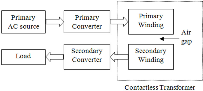 (c)
(c)
Figure 1. Axial contactless transformer structures (a) Coaxial; (b) Face to face; (c) Block diagram of a CSS.
windings, the contactless transformer reveals a low magnetic coupling coefficient. This results in storing a portion of the total supplied energy into the magnetic structure itself (mainly within the air gap) rather than transferring it to the secondary. The energy storage is directly related to the coupling. There are two basic energy storing elements; the magnetizing inductance (inversely proportional to the air gap length) and the leakage inductance (related to the windings layout and relative positioning).
The magnetizing inductance of such a transformer is much lower than that of a compactly coupled counterpart. As a result, in addition to the reflected load current, the primary winding carries an increased magnetizing current, in turn, increasing the primary-side conduction losses. Again, by the reason of air gap inclusion and the availability of alternative magnetic-flux paths (air space) rather than the ideal core path, the contactless transformer also exhibits increased leakage inductance in both windings. The increased leakage inductance, which appears in series with the windings, causes a voltage drop across them, resulting in the reduced voltage gain. At the same time only a portion of the primary current is being reflected to the secondary side as the rest is being drawn by the low magnetizing inductance [8]. Furthermore, whenever an air gap is introduced into a magnetic path, the magnetic field lines will “fringe” outward as they cross the air gap as shown in Figure 2. These fringing fields will increase the effective cross-sectional area Ag of the air gap. One way to correct this effect is by adding the length of the gap to the dimensions of the core center-pole cross-section. To avoid what could be a significant error, the inductance calculation must be based upon the effective gap area rather than the actual center-pole area. Therefore, a range of experiential methods have been developed for correcting this effect. For a core with a rectangular center-pole (cp) with cross-section dimensions (a and b), the effective gap area, Ag is approximately [9] is,
 (1)
(1)
Similarly, for a round centre-pole with diameter Dcp,
 (2)
(2)
Thus, to achieve the desired inductance, the gap area must be modified by using the above correction method.
4. Obtaining Electrical Model from Geometry
The purpose of modeling the transformer as an electrical network is to offer an improved analysis of the transformer performance, simulation, derivation of mathematical equations to put a figure on each aspect of a magnetic component. Moreover, it helps to define the magnitude and location of relevant parasitic magnetic elements to enable prediction of performance effects. The duality method is proposed decades ago and it’s based on finding the equivalent magnetic circuit by identifying the different magnetic flux paths in it. Then using the duality between magnetic and electric quantities, the reluctance model then is converted to an electric equivalent network [10]. Figure 3 shows the flux paths of the contactless transformer used for contactless slipring system. The primary current is flowing in the primary winding sets up an mmf

Figure 2. Fringing flux around the air gaps.

Figure 3. Flux paths of the contactless transformer.
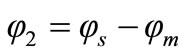
(N1I1) which is considered as a driving mmf. If a load is connected to the secondary winding, then the induced current in the secondary winding produces a back-mmf (NsIs) which its associated flux φ2 opposes the primary flux φ1 (and thus subtract from it) as illustrated in Figure 3. The resultant of these two mmf’s is the working main flux φm (mutual flux) is given by,
 (3)
(3)
Where
 (4)
(4)
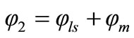
Referring to Figure 3; the leakage stray flux lines (φst1 and φst2) in contactless transformer do not have a priori known path, therefore, it is inaccurate to model them with a reluctance network. Thus, fringing fields around the gaps will be ignored, except the effective gap area might be corrected to take the fringing field into account as presented in Section 3. Therefore, the total flux linked by each winding can be divided into two components: a mutual component φm that is common to both windings, and a leakage flux components (φlp and φls) that links only the winding itself. In terms of these flux components, the total flux by each of the windings can be expressed as,
 (5)
(5)
 (6)
(6)
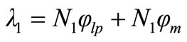
For N1 and N2 as primary and secondary number of turns, the primary and secondary windings flux linkage then are given by,
 (7)
(7)
 (8)
(8)
Based on the above relationships for the flux linkages, the primary and secondary inductances are also divided into two components (the leakage inductances and the magnetizing inductances) as following,
 (9)
(9)
 (10)
(10)
The mutual inductances as well are given as,
 (11)
(11)
The above self-inductances plus the mutual inductance then are determined from modelling the physical structure of contactless transformers. The reluctance of each region of the structure is calculated from its area, length and permeability [Equation (12)], and inserted with its specific value into the appropriate location in the reluctance model, as shown in Figure 4. The magnetic field sources (ampere-turns) of the windings are assigned to any discrete point where the flux is not divided.
 (12)
(12)
The series reluctances for the same core section with the same dimensions can be summed giving the primary and secondary core reluctances as following,
 (13)
(13)
 (14)
(14)
Generally, the air gap reluctances are much greater than the adjacent ferrite core legs in Figure 4. This indicates the reluctance of the air-gap is governing and restrains the magnetic flux that is remaining through the core. Therefore, the core reluctances could be eliminated from the reluctance model. This leads to the simplified reluctance model as shown in Figure 5.
A dual now needs to be created for the magnetic circuit

Figure 4. Reluctance model of the contactless transformer.
of Figure 5 following the duality relationships between the two networks. For instance, in a reluctance model, nodes are the meshes in the electrical model. Similarly, open branch will be shorted, series will be parallel, mmf is a voltage source, and a reluctance is a permeance in the electrical network.
Figure 6 shows a permeance network of the reluctance model after applying a network transformation between the two networks. Permeance is the reciprocal of reluctance and can be calculated as follows,