Prediction and Analysis of Deposition Efficiency of Plasma Spray Coating Using Artificial Intelligence Method ()
1. Introduction
The role of surface coatings has become increasingly demand for various engineering applications in industries because requirement of high efficiency and longer service life of the equipment [1-4]. Thermal spraying holds a unique position in the spectra of surface modification technologies because it can provide thick coatings over 100 μm over a large area at a very high application rate compared with other coating processes such as PVD, CVD and electroplating [5,6].The conventional plasmaspraying process is commonly referred to as air or atmospheric plasma spraying (APS). In this APS technology, the coating materials used with well-defined melting point ranging from metallic and ceramic materials to polymeric material [7]. To generate the plasma, an inert gas typically argon or argon+ hydrogen mixture is superheated by a direct-current arc [8]. Plasma temperatures in the power heating region range from approximately 6000˚C to 15000˚C, which are significantly above the melting point of any known material [7]. The materials in the form of powder mixture (Flay-ash+quartz+
illmenite powder composite) are injected into a hightemperature plasma flame. The powder mixture (size from 40 µm to 100 µm) is then rapidly heated and accelerated to a very high velocity by the plasma flame, impacts the surface of the substrate material in the form of molten or semi-molten state and very quickly cools to form a high-quality coating [8,9-11]. The quality control of plasma spray technique generally considers the monitoring of the molten feedstock particle characteristics, deposited at the substrate surface i.e. to increase the coating efficiency [12]. The deposition efficiency is the main requirements of the coatings developed by plasma spraying. It is defined as the ratio of the weight of coating deposited on the substrate to the weight of the expended feedback. Deposition efficiency represents the effectiveness of the deposition process as well as the coatability of the powder under study [13]. In this decade, Mishra et al. attempt to spray different type of raw material and fly-ash mixture on metal substrates through plasma spraying and studied the behavior of coating deposition efficiency [14-17]. Plasma spraying process depends on the operating conditions, the desired properties of the final coating, etc. Besides the intrinsic material properties, the technical requirements for the plasma spray feedstock powders include good flowability and sprayability. They are greatly affected by the particle size, shape and morphology as well as particle size distribution [18]. Hence the coating deposition efficiency directly or indirectly depends on many other parameters during spraying, in which each one is inter-related with each other. ANN study and design of systems capable of perceiving their environment & taking actions maximizeing their chance of success and to increase deposition efficiency.
A neural network is a mathematical model processing system which is capable to relate input to output parameters and learning from data set through iteration, without requiring a prior knowledge on the relationships between the process variables [19]. This model can able to approximate various nonlinearities in the data series, among other models [20-22] and can give an appropriate optimized data output (Deposition efficiency).
2. Experimental Procedure
Mixture of Flay-ash, Quartz and illmenite used as a composite coating material on the Copper and Mild Steel substrates. Flay-ash, Quartz and illmenite mixture was taken with their weight percentage ratio of 60:20:20 and mechanically milled in a FRITSCH-Planetary ball mill for 3 hour to get a homogeneous mixture. This mixture used as feed stock for plasma spraying was first sieved and four different size i.e. 100 µm, 80 µm, 60 µm and 40 µm are separated out. The substrate materials have dimensions of 1 inch diameter and 3 mm thickness. The substrate were grit blasted at a pressure of 3 kg/cm2 using alumina grit to make the surface roughness ~5.00 Ra. After grit blasting substrates surface were cleaned by acetone and then immediately plasma spraying was carried out. The coating process made by using a 40 KW dc power supply plasma spray system at the Laser & Plasma Technology Division, BARC, Mumbai. The plasma input power level was varied from 11 KW to 21 KW. This is a typically atmospheric plasma spray process, which is working in the non-transferred arc mode. The injection of the powder from the torch nozzle directed perpendicular to the plasma flow and parallel to the torch trajectory. The torch was operated using argon (Ar) and Nitrogen (N2) plasma mixture gas. The major subsystems of the set up include the power supply, powder feeder, plasma gas supply, plasma spraying torch, and substrate to torch distance controller, cooling water and spray booth. For cooling the system, a water cooling system used which is a four stage closed loop centrifugal pump, regulated at a pressure of 10 kg/cm2 supply. Operating parameters used for coating deposition are given in Table 1. Flow rate of plasma gas (argon) and Secondary gas (N2) are kept constant. Powder feed rate, Powder Size and Torch to base distance (TBD) are varied with respect to increase in power level.
3. Artificial Neural Network
Artificial neural network is a technique that involves database training to predict property-parameter (output) evolutions, more quickly [23,24]. This section presents the database construction, implementation protocol and a set of predicted results for coating deposition efficiency [25]. ANN of simple processing elements (neurons) typically organized in layers (input layers, hidden layers and output layers) shown in Figure 1. Each neuron receives multiple inputs in proportion to their connection weights and generates a single output which may be propagated to several other neurons [26]. A software package NEURALNET for neural computing developed, by using back propagation algorithm as the prediction tool for output (coating deposition efficiency) [27]. The procedure to find out the deposition efficiency for plasma spraying is described as:
Step 1. Input training parameters: Among all data set, 75% data set are taken as Input (parameter set includes V, I, Torch to base distance, powder federate and powder size and deposition efficiency) to train and define the ANN architecture.
Step 2. Input testing parameters: In this step, remains 25% of data set enters by excluding its output parameter (deposition efficiency) value.
Step 3. Adjust the number of neuron for layers for training.
Step 4. Training process: Execute the training set builder program, in order to build the training set for the
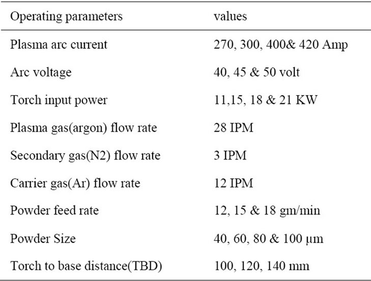
Table 1. Operating parameters during deposition of Flyash+ quartz+ illmenite coatings.
learning of ANN.
Step 5. Test process: After training process, the output value of above 25% data set is observed.
Step 6. Error percentage calculation: in this step, the ANN deposition efficiency of testing data is compare with that of experimental data. The test error is an important quantity since it can be viewed as an estimate of the generalization error. This should not be too large compared to training error, in which case one must suspect that the network is over-fitting the training data [28].
Step 7. If there is a greater error percentage, then set the neuron number of Step 3 and execute the evaluator in order to find the optimal values.
Step 8. Prediction for experimental input: Again the whole experimental input data enters to find out the ANN predicted deposition efficiency.
Step 9. Compare the neural network response of step-5 and the optimal solution of step-7 in order to evaluate the problem recognition capability of neural network.
There are no fixed rules for developing an ANN, but through a general framework it can be followed based on previous successful applications in engineering. The aim of an ANN is to normalize an input-output relationship of the form of:
ym = ƒ(xn)
where, xn is an n-dimensional input vector represents variable parameters x1, ··· xi, ··· xn and ym is an m-dimensional output vector represents the resulting variables y1, ··· yi, ··· ym. In plasma spray modeling, values of x may be Current, Voltage, Torch-to-base distance, powder federate and powder size.
4. Results and Discussion
A software package NEURALNET is used for neural computing, developed by Rao and Rao [27], which can predict the coating deposition efficiency. Operation of database undergoes between three categories step i.e. input, hidden layer and out-put layer which are graphically present in Figure 1. About 12 data sets including voltage, current, torch to base distance, powder feed rate, powder size are taken to train the neural network used for predicting coating deposition efficiency. With varying number of neurons in the hidden layer are tested at constant cycles, learning rate, error tolerance, momentum parameter and noise factor and slope parameter. Based on least error criterion, one structure given in Table 2 is selected for training of the input-output data. The learning rate is varied in the range of 0.002 - 0.100 during the training of the input-output data. The network optimization process (training and testing) is conducted for 10,000,000 cycles for which stabilization of the error is obtained. The number of cycles selected during training is high enough so that the ANN models could be rigorously trained. Neuron numbers in the hidden layer is varied and in the optimized structure of the network this number is 8 (for Copper) and 6 (for Mild Steel).
4.1. Predicted Deposition Efficiency Compare with Experimental Results Based on Different Feed Rate
In Figure 2, there is a comparative study of ANN prediction value of coating deposition efficiency with that of experimental value for copper substrate. There are two comparison plot to confirm the error between ANN prediction and experimental. In plot (a1), the fly-ash+ quartz+illmenite powder mixture are deposited on copper substrate at 12 gm/min feed rate, 100 mm torch to base distance with varying the power level. In plot (b1), the powder mixture are deposited at 18 gm/min feed rate, 140 mm torch to base distance. As seen from the figure, the close agreement of the values of the coating deposi-

Table 2. Input parameters selected for training.

Figure 2. Comparison plot between ANN Prediction deposition efficiency and experimental value of Copper (plot a1) at 12 gm/min feed rate and (plot b1) at 18 gm/min feed rate (fly-ash+quartz+illmenite powder mixture are deposited on Copper substrate).
tion efficiency by the neural network and the experimental study clearly indicates that the model can be used for predicting the amount coating deposition efficiency. For Mild steel substrate the comparison plots are shown in Figure 3 by varying power level. In plot (a2), the powder mixture 12 gm/min feed rate, 100 mm torch to base distance. In plot (b2), the powder mixture are deposited at 18 gm/min feed rate, 140 mm torch to base distance.
4.2. Comparisons between Mild Steel & Copper Substrate in Account of ANN PREDICTED “Rate of Deposition Efficiency” Results
Figure 4 shows the coating deposition efficiency for Copper and Mild Steel substrate. In each substrate it is clearly observe that by increasing the power level from 11 KW by taking any of the feed rates ranging from 12 gm/min to 18 gm/min, the coating deposition efficiency increases up to a certain limit (~19 KW) and further increase in power level, there is decrease in rate of deposition efficiency. These results can be clearly detected from the SEM figure of substrate deposited surface, which is shown in Figure 5. The image analysis of the splats on the substrate surface allows determining their size and shape factors versus the substrate nature, temperature [29]. There is a comparison SEM structure of deposition efficiency for Copper substrate at 18 KW, which is nearly highest deposition efficiency (shown in Figure 5(a)) with 21 KW, which leads to decreasing in “rate of deposition efficiency” (shown in Figure 5(b)). In 18 KW power level there is uniform spreading of splats and there is less inter splat cavity. But when we go for 21