World Journal of Mechanics
Vol. 1 No. 4 (2011) , Article ID: 7125 , 7 pages DOI:10.4236/wjm.2011.14022
Micro Crack of Aluminum Sheet during Cold Rolling*
1School of Mechanical, Electronic and Control Engineering, Beijing Jiaotong University, Beijing, China
2State Key Laboratory of Tribology, Tsinghua University, Beijing, China
E-mail: zhhzhang@bjtu.edu.cn
Received June 10, 2011; revised July 7, 2011; accepted July 16, 2011
Keywords: Aluminium Sheet, Micro Crack, Cold Rolling, Emulsion
ABSTRACT
The micro crack of aluminum sheet during cold rolling lubricated with emulsions is investigated. Experiments show that micro cracks occur after cold rolling process and this is attributed to various parameters, for instance, the thin oxide film formed at the sheet surface. The micro crack spacing thus becomes an important parameter which deserves more concerns. The aspect ratio of these micro cracks is then analyzed theoretically, which takes into consideration of the oxide fracture process. The good agreement between the observations and the theoretical predictions validates the analysis. The approach can shed some new lights on the mechanical process of aluminium sheet during cold rolling.
1. Introduction
Aluminium alloy sheets are widely used in the car, ship building and aerospace industries as substitutes for steel sheets and fiber reinforced plastic panels, due to their excellent properties such as high strength, corrosion resistance, and weld abilities [1]. Cold rolling is one of the fundamental methods for introducing plastic deformation of alloys such as aluminium, zirconium, titanium alloys, etc. The importance of tribology of the flat process in aluminium sheet manufacture is considered in economic terms. One of the important parameters in the forming of aluminium sheets is lubrication. Control of lubrication is the main barrier to improving productivity and surface quality.
Friction and the surface quality of the rolled strip are closely related to the amount of oil drawn into the bite and the surface roughness on the rolls and the in-going strip [2]. The most common procedure to measure the pressure and frictional stress distribution in the roll gap in favor of frictional conditions is to use pin-type sensor. By using a strain gages, the elastic deformation of the roll is measured and is used to calculate the stresses between the sheet and the roll [3]. In common sense, the averaged frictional coefficient depends critically on a large number of variables. Speed of rolling, which is identified as the most important parameter when the friction coefficient is concerned, the Lai-Seng et al’s experiments [4] tells.
Friction models are used in the cold metal rolling industry to increase productivity and to improve surface quality via better online control and off-line scheduling. Measurements of changes in surface roughness during cold rolling with mixed lubrication by Sutcliffe et al. show that short wavelength components persist longer than long wavelength components, mirroring the results for dry rolling [5,6]. A two-dimensional frictional model has been developed for cold metal rolling in the mixed regime to account for the experimental outcomes, where the hydrodynamic pressure in the lubricant is solved by using Reynolds’ equation coupled with the crushing process of the two-wavelength roughnesses [7]. In another analysis model, the average Reynolds for Christensen surfaces, which is developed as a convenient approximation for the Gaussian distribution, with the arbitrary Peklenik surface pattern parameter is combined with an analysis flattening under conditions of bulk plastic flow to treat lubrication in the mixed regime [8].
Elastic deformation of the sheet plays a very significant role in film thickness formation where elastic deformation of the rolls results in some interesting phenomena such as lengthening of the work zone and the occurrence of a pressure spike [9]. Saeed et al. made a comparison of cold rolling theories based on the equilibrium approach, without using average constant frictional coefficients [10]. Cambiella et al. discovered that the interactions between metal surface and emulsifier molecules, which are related to the pH value of the surfactant solution, play key roles in the mechanism of emulsion lubrication [11]. Second-order average Reynolds equation, eliminating the need to introduce an unknown flow constant is adopted, by Qiu et al. [12]. The equation was further extended to incorporate variable yield stress characteristics of the workpiece in the roll bite to allow for work-hardening effect.
The trapped and pressurized lubricant, which is to offer “hydrostatic” load-carrying ability and to reduce the conformation of the workpiece to the tool, tends to reduce the contact area and friction stress, but it may also interfere with the transfer of surface texture to the workpiece. The amount of escaping lubricant from the micro-pools usually dominates the pattern of surface finish [13]. In literature, a secondary lubrication mechanism, called micro-plasto hydrodynamic lubrication or micropool lubrication, associated with the trapped lubricant is proposed by Mizuno and Okamoto [14]. Ahmed and Sutcliffe described a method to analyze three-dimensional surface topography obtained from cold-rolled stainless steel samples to identify hydrodynamic pits and roll marks on the surface, by considering the local differences in height between the pits and the un-pitted regions [15]. The results suggest that hydrodynamic action may prevent the elimination of the pits [16], and it applies to the aluminium foil rolling, where roll marks are the dominant feature.
With sufficiently high viscosity and sliding speed, the lubricant trapped in the micro-pools between the tool and the workpiece can be drawn into the interface [17,18]. Furthermore, the mechanism of pit elimination in strip drawing and rolling of stainless steel strips was investigated, and strip drawing tests with artificial indents confirm the role of micro-plasto-hydrodynamic lubrication in allowing pits to be reduced in size and depth. It is suggested that the presence of an oil film in the unpitted region prevents generation of pressure differences between the pits and the unpitted regions [19]. There are at least three mechanisms in rolling which determine the lubricant pressure in the pits and their potential elimination: 1) hydrodynamic entrainment of oil in the inlet zone, 2) hydrodynamic action inside the pits due to relative sliding in the bite, and 3) hydrostatic action in isolated pits.
All metals and alloys form some kind of transfer layer (TL) in rolling processes, first manifested in practice by a colour change of the roll surface. By using the plain strain compression test (PSCT) of aluminium strip in conjunction to surface analysis techniques including time-of-flight secondary ion mass spectroscopy (ToFSIMS), experimental investigation is conducted by Sutcliffe [20]. A few indents later, a transfer layer built up on the tool, leading to a significant fall in friction factor. In fact, mechanically mixed layers (MMLs) and transfer layers are presented in the metal forming industry, for instance, in rolling processes among others. The occurrence of one or the other layer depends mostly on lubricant (average oil film thickness and efficiency of additives) and the nature of the rolled alloy, either by the presence of hard, TL-abrading second phase particles, or the ductility or brittleness of the oxide layer [21]. Such a transfer is also commonly encountered in cold rolling practice, for example, Chambat et al. examined used rolling lubricants and confirmed that a variety of chemical reactions involving aluminium and boundary additives took place during aluminium cold rolling [22]. All these phenomena are made possible by the fracture of the surface oxide layer and exposure of fresh metal surface. An oxide film is formed on aluminium very rapidly when it is exposed in air. The effect of oxide film thickness on the oxide layer fracture and metal extrusion behaviour are established, by generating a thicker anodized oxide film on the aluminium to facilitate the observation of the fracture behaviour of the oxide film during rolling [23].
The lubrication with emulsions in cold aluminium rolling has drawn broad investigations [24-29]. Emulsions are composed of three primary ingredients: the oil, the water phase, and the emulsifier. Most metal working emulsions are oil-in-water (o/w) emulsions where the oil is the dispersed phase and the water is the continuous phase. The fundamental problem in the use of emulsions is the behavior of the oil particles. Al-Sharif et al. modeled lubrication with liquid-liquid emulsion, including o/w emulsion and its inversion, i.e., water-in-oil (w/o) emulsion [24]. In Elastohydrodynamic (EHD) mode, the film thickness varies linearly with the logarithm of the droplet radius, and also with the inlet volume fraction [27]. During metal working process, lubricant may be entrapped in microscopic surface pockets or pits to offer “hydrostatic” load-carrying ability and to reduce the conformation of the workpiece to the tool (the roll). Oil pooling can occur in cold rolling with inlet oil volume fraction as little as 0.1, and an increase in the yield stress of the workpiece leads to increased volume fraction, i.e., enhanced pooling ahead of the conjunction [25]. When the emulsion is formed, the hydrophilic groups orient towards the water phase and the lipophilic hydrocarbon chains orient toward the oil phase. A model for o/w emulsion has been developed by Lo et al., based on a group of viscosity coefficients transiting smoothly and incessantly from the thick film region to the thin film region [29].
The purpose of the present work is to investigate the characteristics of aluminium sheet rolling with a micro emulsion, wherein the micro crack features are explored and modeled in detail.
2. Experimental Procedure
2.1. Equipment
Two kinds of rolling mill with the same roll radii R are used, i.e., model 1400 mm and model 2800 mm. The radius of the roller is about 325 mm. The width of the roll with model 2800 is of 2800 mm, having a ground circumferential finish with a root mean square surface roughness (Rq) of about 0.5 um. The roll hardness is 95 HS (~67 HRC).
2.2. Aluminium Alloy
Flat aluminium sheet with alloy compositions, 5052, summarized in Table 1 is used in the cold rolling condition [30]. The width of the aluminium sheet is about 1000 mm - 1500 mm. Aluminium sheet is cold rolled from 6 mm to 3 mm (with totally reduction of 50%) in thickness through three passes. The cold rolling routine is described as follows: 6→4.9→3.9→3 (mm).
2.3. Lubricant
Rolling was carried out with lubricant of micro emulsion wherein water is the continuous phase and the oil disperse phase to form oil-in-water emulsion. The maximum emulsion supplying rate is of 220 L/min. The fluid pressure at exit is 2kg/mm. The under load applied is 500 - 700 tons.
The base oil of the micro emulsion includes synthetic ester and mineral oil. Additives are listed below: Oleyl alcohol EO4 Phosphate ester, Methyl laurate, Sorbitan monooleate, Hexaoleyl sorbitate EO50, Oleic acid, Alkyl amine EO2, C12-14 tert Alkyl amine EO5, and Dioctyldiphenylamine. The further exact chemical formulations of the emulsions are proprietary and have not been disclosed to the researchers. The viscosity of the micro emulsion is 2.02 cst at 90˚C with 95 wt%.
3. Experimental Results
Typical optical micrographs of the sheet surfaces are shown in Figure 1. Micro cracks are seen in the oxide film near the entry, running perpendicular to the rolling direction, even though they are somewhat skewed by the initial roughness. The results also show how the micro cracks open up through the bite and aluminium is extruded through the cracks, leaving a sheet surface which is a combination of porous oxide fragments and brighter areas of extruded aluminium metal.
Oxide films are fractured during rolling process. In all cases micro cracks occur at the entry to the roll bite. Oxide films thinner than 1.5 um are broken again into smaller pieces in the roll bite, with a final aspect ratio of length to thickness equal to about 10. Aluminium is extruded through the cracks in the roll bite as the cracks open up and the substrate deforms. Thus the final sheet surface is made up of oxide fragments and newly generated metal surfaces.
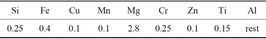
Table 1. Compositions of 5052 aluminium alloy (in wt%).
 (a)
(a)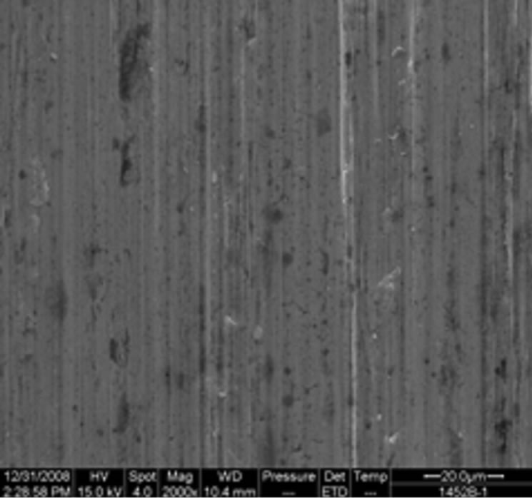 (b)
(b)
Figure 1. Micrographs showing micro-cracks on the sheet surfaces: (a) with Model 1400 mill used; (b) with Model 2800 mill used.
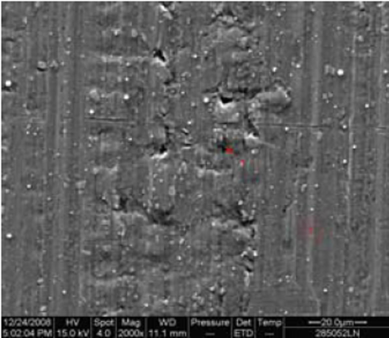
X-ray photoelectron spectroscopy (XPS) is a quantitative spectroscopic technique that measures the elemental composition, chemical state and electronic state of the elements that exist within a material. XPS result of Aluminium sheet rolled by Model 2800 mill is shown in Figure 2. XPS analysis shows that nearly none of C element can be seen. This tells that corrosion is of little possibility during cold rolling. Furthermore, substrate aluminium will extrude through cracks.
4. Model Analysis
It must be assumed that the material is incompressible in the plastic state and obeys the von Mises criterion of plastic flow and its associated flow rule. The oxide film of the out layer of the aluminium sheet is assumed to be inextensible. It will be assumed that the rolls have a longitudinal roughness lay, the roll and sheet surfaces have similar autocorrelation lengths initially and are uncorrelated, and the surface slopes are relatively small.
 (a)
(a)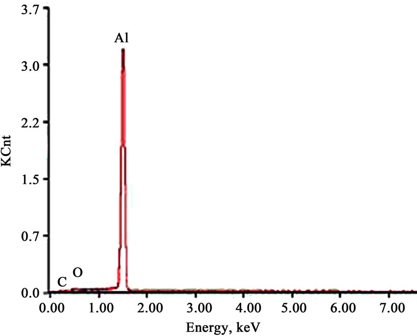 (b)
(b)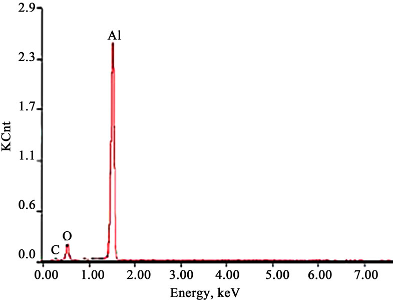 (c)
(c)
Figure 2. SEM and XPS photos of aluminium sheet (5052) rolled by Model 2800 mill.
The crack spacing is an important parameter to model as it determines the way in which fresh aluminium becomes exposed to additives in the lubricant and ultimately makes contact with the roll surface. In the next section, the model process is divided into following two steps.
Step 1: Modeling the initiation of micro cracks at the roll bite A model accounting for the initiation of micro cracks in the entry bite region is followed with the works of Le and Sutcliffe [23]. The geometry at the entry point is shown schematically in Figure 3. The elastic plastic nature of the deformation induces deformation (sinkage) of the sheet ahead of the contact, with associated stretching of the oxide film layer. A priori micro crack is located the PP’ plane in the oxide film layer of thickness tc (which is typically of about 1 um in thickness deduced from the SEM results). As it moves forward, the development of stresses in the intact oxide film layer is examined to predict when the next crack will occur and the corresponding crack spacing. It is found that the longitudinal stress in oxide layer film develops as the plane PP’ approaches the bite, due to elastic stretching of the surface of the aluminium sheet. The maximum longitudinal stress in the oxide film layer occurs at a plane OO’, with a distance d behind PP’, where the shear stress on the interface changes sign.
A crack will initiate in the brittle oxide film layer at the location of maximum stress when the maximum stress reaches the strength of the oxide film σ f. Such a crack will relieve the stresses in the inlet, with stresses able to rise again once the crack has travelled into the bite. The corresponding distance between the location of the maximum stress and the previous crack plane gives the micro crack spacing. For constant oxide strength a fall in crack spacing will occur with reducing oxide film thickness. A more detailed analysis of the stresses at the leading edge of the oxide film layer (in the presence of a crack) would be needed to quantify the dependence of the crack spacing on the oxide film layer thickness and material properties.
Step 2: Modeling the cracking within the roll bite A model similar to ‘shear lag’ models used in composite material theory to predict fibre cracking is developed. The geometry of an oxide fragment of length λ at the interface between roll and aluminium sheet is shown in Figure 3.
Because the length of the oxide fragment is short compared with the roll radius, the roll and oxide surface can be modeled as flat. The normal pressure acting on the top and bottom surfaces of the oxide film is taken as constant along the oxide fragment and approximated by the plane strain yield stress Y of the bulk substrate.
Within the roll bite the substrate metal (aluminium) extends plastically in the rolling direction. It is assumed that the oxide fragment does not elongate significantly in the bite. Hence there is relative slip between the oxide fragment and the substrate and an interfacial shear stress τi is developed between the oxide and substrate. We assume that the oxide film is well bonded to the substrate, with a shear strength equal to the shear strength k (= Y/2) of the substrate. Although there may be a region of sticking between the oxide and the substrate in the middle, the extent of this region will be small due to the large difference in strains. Hence it is assumed that there is slipping all along the interface, with the interfacial shear stress τi equal to the limiting value of k. In addition a friction stress τr acts between the top surface of the oxide and roll. This acts along the rolling direction over the whole length of the oxide fragment, because the roll surface is moving faster than the sheet in the entry region. This contact is modeled using a Coulomb friction law (because of the fact that the lubrication is in typically boundary lubricating state or in the mixture lubricating state), i.e.,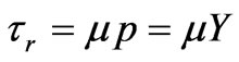 .
.
The surface tractions give rise to a longitudinal tensile stress σ within the oxide fragment. For the conditions illustrated in Figure 4, there is a position along the fragment where the oxide and substrate travel at the same speed. At this point the sign of the interfacial shear stress τi changes to the opposite, so that a friction hill is developed similar to that predicted for rolling. The distances to the neutral point from the two ends of the fragment are denoted with ξA and ξB, respectively. The overall balance of lateral forces on the oxide fragment gives the following relation
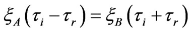 (1)
(1)
Since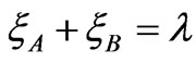 , the neutral point is located a

Figure 3. Schematic view for the crack initiation.
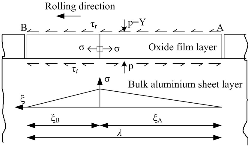
Figure 4. Model for roll bite oxide film fracture due to extension of the bulk metal.
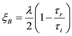 (2)
(2)
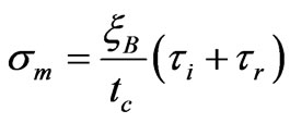
As the oxide is assumed to be flat, the lateral stress in the film does not vary through the thickness of the oxide fragment. The maximum tensile stress σm in the oxide occurs at the neutral point, with a value of
 (3)
(3)
The fragment will break into smaller pieces when this stress equals the tensile strength of the oxide film σf. Hence, by using Equations (1) - (3) and introducing the assumed interfacial stresses relation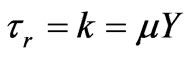 , the maximum aspect ratio
  of the oxide fragment which does not break can be derived as
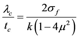 (4)
(4)
Equation (4) shows that the critical aspect ratio is determined by the ratio of the oxide tensile strength to the shear yield stress of the substrate. It also indicates that the effect of frictional stresses is not critical as long as the effective friction coefficient is significantly less than 0.5.
For the experimental conditions described above, the shear yield stress of the substrate is about 170 MPa - 215 MPa. Using a value of the friction coefficient 0.2 and an oxide tensile strength of 500 MPa, it predicts a critical aspect ratio of about 6.84. This agrees well with measurements of crack spacing presented in Figure 1. This means that the proposed model is valid in case of aluminium cold rolling with micro emulsions used as boundary lubricant and coolant.
5. Conclusions
Aluminium sheets are cold rolled with two models of mills: Model 1400 and Model 2800. The micro-cracks running perpendicular to the rolling direction are formed near the entry of the bite, leaving a sheet surface which is a combination of porous oxide fragments and brighter areas of extruded aluminium metal.
Models of the oxide fracture has been developed which show good agreement with measurements in case of aluminium sheet cold rolling with micro emulsions used as boundary lubricant and coolant.
REFERENCES
- S. Toros, F. Ozturk and I. Kacar, “Review of Warm Forming of Aluminum-Magnesium Alloys,” Journal of Material Processing Technology, Vol. 207, No. 1-3, 2008, pp. 1-12. doi:10.1016/j.jmatprotec.2008.03.057
- J. A. Schey, “Surface Roughness Effects in Metalworking Lubrication,” Lubrication Engineering, Vol. 39, 1983, pp. 376-382.
- D. J. Meierhofer and K. A. Stelson, “Measurement of the Interfacial Stresses in Rolling Using the Elastic Deformation of the Roll,” Journal of Engineering Industry, Vol. 109, 1987, pp. 362-369. doi:org/10.1115/1.3187140
- L. Lai-Seng and J. G. Lenard, “Study of Friction in Cold Strip Rolling,” Journal of Engineering Material Technology, Vol. 106, No. 2, 1984, pp. 139-146. doi:org/10.1115/1.3225688
- M. P. F. Sutcliffe, “Flattening of Random Rough Surfaces in Metal Forming Processes,” Journal of Tribology, Vol. 121, 1999, pp. 433-440. doi:org/10.1115/1.2834086
- M. P. F. Sutcliffe and H. R. Le, “Measurements of Surface Roughness in Cold Metal in the Mixed Lubrication Regime,” STLE Tribology Transactions, Vol. 43, 2000, pp. 39-44. doi:org/10.1080/10402000008982310
- H. R. Le and M. P. F. Sutcliffe, “A Friction Model for Cold Strip Rolling with Two-wavelength Surface Roughness in the Mixed Lubrication Regime,” Journal of Tribology, Vol. 125, 2003, pp. 670-677. doi:org/10.1115/1.1538191
- H. S. Lin, N. Marsault and W. R. D. Wilson, “A Mixed Lubrication Model for Cold Strip Rolling—Part I: Theoretical,” STLE Tribology Transactions, Vol. 41, No. 3, 1998, pp. 317-326. doi:org/10.1080/10402009808983754
- P. M. Lugt and W. E. ten Papel, “The Influence of Elastic Deformation of the Roll and the Sheet in a Hydrodynamically Lubricated Cold Rolling Process,” Journal of Tribology, Vol. 117, No. 3, 1995, pp. 468-475. doi:org/10.1115/1.2831277
- U. Saeed and G. A. Lenard, “A Comparison of Cold Rolling Theories Based on the Equilibrium Approach,” Journal Engineering Material Technology, Vol. 102, No. 2, 1980, pp. 223-228. doi:org/10.1115/1.3224801
- A. Cambiella, J. M. Benito, C. Pazos, J. Coca, M. Ratoi, and H. A. Spikes, “The Effect of Emulsifier Concentration on the Lubrication Properties of Oil-in-Water Emulsions,” Tribology Letters, Vol. 22, 2006, pp. 53-65. doi:org/10.1007/s11249-006-9072-1
- Z. L. Qiu, W. Y. D. Yuen and A. K. Tieu, “Mixed-film Lubrication Theory and Tension Effects on Metal Rolling Processes,” Journal of Tribology, Vol. 121, No. 4, 1999, pp. 908-915. doi:org/10.1115/1.2834154
- S. W. Lo and K. J. Chung, “The Optimum Condition of Manufacturing a Smooth Engineered Surface by Internal-ironing Process,” Tribology Transactions, Vol. 41, 1998, pp. 563-571. doi:org/10.1080/10402009808983783
- T. Mizuno and M. Okamoto, “Effects of Lubricant Viscosity at Pressure and Sliding Velocity on Lubricating Conditions in the CompressionFriction Test on Sheet Metals,” Journal of Lubrication Technology, Vol. 104, 1982, pp. 53-59. doi:org/10.1115/1.3253164
- R. Ahmed and M P. F. Sutcliffe, “Identification of Surface Features on Cold Rolled Stainless Steel Strip,” Wear, Vol. 244, No. 1-2, 2000, pp. 61-70. doi:org/10.1016/S0043-1648(00)00442-7
- H. R. Le and M. P. F. Sutcliffe, “Analysis of Surface Roughness of Cold-rolled Aluminium Foil,” Wear, Vol. 244, 2000, pp. 71-78. doi:org/10.1016/S0043-1648(00)00441-5
- S. W. Lo and W. R. D. Wilson, “A Theoretical Model of Micro-Pool Lubrication in Metal Forming,” Journal of Tribology, Vol. 121, No. 4, 1999, pp. 731-738. doi:org/10.1115/1.2834129
- M. P. F. Sutcliffe, H. R. Le and R. Ahmed, “Modeling of Micro-pit Evolution in Rolling or Strip-Drawing,” Journal of Tribology, Vol. 123, 2001, pp. 791-798. doi:org/10.1115/1.1352741
- R. Ahmed and M. P. F. Sutcliffe, “An Experimental Investigation of Surface Pit Evolution during Cold-rolling or Drawing of Stainless Steel Strip,” Journal of Tribology, Vol. 123, 2001, pp. 1-7. doi:org/10.1115/1.1327580
- M. P. F. Sutcliffe, R. Combarieu, M. Repoux and P. Montmitonnet, “Tribology of Plane Strain Compression Tests on Aluminium Strip using ToF-SIMS Analysis of Transfer Films,” Wear, Vol. 254, No. 1-2, 2003, pp. 65-79. doi:org/10.1016/S0043-1648(02)00295-8
- P. Montmitonnet, F. Delamare and B. Rizoulieres, “Tran- sfer Layer and Friction in Cold Metal Strip Rolling Processes,” Wear, Vol. 245, 2000, pp. 125-135. doi:org/10.1016/S0043-1648(00)00473-7
- F. Chambat, M. Lashermes and H. Hendricks, “Organometallic Compounds Produced during Aluminium Cold Rolling,” Lubrication Technology, Vol. 43, 1987, pp. 522-527.
- H. R. Le, M. P. F. Sutcliffe, P. Z. Wang and G. T. Burstein, “Surface Oxide Fracture in Cold Aluminium Rolling,” Acta Materialia, Vol. 52, No. 4, 2004, pp. 911-920. doi:org/10.1016/j.actamat.2003.10.027
- A. Al-Sharif, K. Chamniprasart, K. R. Rajagopal and A. Z. Szeri, “Lubrication with Binary Mixtures: Liquid-liquid Emulsion,” Journal of Tribology, Vol. 115, 1993, pp. 46-55. doi:org/10.1115/1.2920985
- S. H. Wang, A. Z. Szeri and K. R. Rajagopal, “Lubrication with Emulsion in Cold Rolling,” Journal of Tribology, Vol. 115, No. 3, 1993, pp. 523-531. doi:org/10.1115/1.2921669
- K. Chamniprasart, A. Al-Sharif, K. R. Rajagopal and A. Z. Szeri, “Lubrication with Binary Mixtures: Bubbly Oil,” Journal of Tribology, Vol. 115, No. 2, 1993, pp. 253- 260. doi:org/10.1115/1.2920999
- S. H. Wang, A. Al-Sharif, K. R. Rajagopal and A. Z. Szeri, “Lubrication with Binary Mixtures: Liquid-liquid Emulsion in an EHL Conjunction,” Journal of Tribology, Vol. 115, No. 2, 1993, pp. 515-522. doi:org/10.1115/1.2921668
- A. Shirizly and J. G. Lenard, “Emulsions versus Neat Oils in the Cold Rolling of Carbon Steel Strips,” Journal of Tribology, Vol. 122, No. 3, 2000, pp. 550-556. doi:org/10.1115/1.555400
- S. W. Lo, T. C. Yang, Y. A. Cian and K. C. Huang, “A Model for Lubrication by Oil-in-water Emulsions,” Journal of Tribology, Vol. 132, No. 1, 2010, pp. 011801- 011810. doi:org/10.1115/1.4000274
- B. X. Xu, “Bibliography of New Standards and Engineering Applications of Aluminium and Aluminium Alloy Products both at Home and Abroad,” Yingsheng Radio & Visual Press, Beijing, 2004.
NOTES
*This project is supported by National Natural Science Foundation of China, Beijing Natural Science Foundation, Program for New Century Excellent Talents in University, and the Fundamental Research Funds for the Central Universities.