Smart Grid and Renewable Energy
Vol. 3 No. 4 (2012) , Article ID: 24605 , 10 pages DOI:10.4236/sgre.2012.34043
A WiFi-ZigBee Building Area Network Design of High Traffics AMI for Smart Grid
![]()
1Department of Electronic Engineering, City University of Hong Kong, Hong Kong, China; 2School of Engineering & Mathematical Science, City University London, London, UK; 3Department of SEEM, City University of Hong Kong, Hong Kong, China.
Email: ee330015@cityu.edu.hk
Received August 5th, 2012; revised September 5th, 2012; accepted September 11th, 2012
Keywords: Advance Metering Infrastructure; Building Area Network; WiFi; ZigBee; Delay
ABSTRACT
A WiFi-ZigBee hybrid BAN solution, namely WiZBAN, is proposed and implemented to cater for the development of high traffic AMI for smart grid application. It is important to highlight that the major challenge of WiZBAN is to handle the high density environment which results in heavy traffic loading and weak signal propagation. To overcome the captioned problem, Vertical Backbone Communication (VBC) and Horizontal Floor Communication (HFC) are defined for WiZBAN. The WiZBAN consists of WiZBAN Gateway (WiZGW), WiZBAN Meter Hub (WiZBAN) and WiZBAN In Home Display (WiZIHD) which caters for the smart grids services including smart metering and demand response. The WiZGW is the entrance of WiZBAN and connects WiZBAN to utilities. The WiZGW also teams up with WiZMH to enables VBC. On the other hand, WiZMH serves as the interception point of VBC and HFC. It interacts with smart meters and sets up the HFC together with WiZIHD to provide the user interface for end users. To shorten the transmission time, WiFi is adopted for VBC while ZigBee is applied to HCF to overcome the weak signal propagation. To investigate the performance of WiZBAN, a case study has been conducted based on an existing 23 floor residential building. From the measured and simulated results, the average round trip delay of demand response and smart metering are found to be 0.6 s and 9 s respectively.
1. Introduction
Smart grid is well recognized by scientists as effectively way out of the global warming. The battle between global warming and environment is identified by the international society. Scientists devote their effort to develop renewable energy and governments control energy consumption by issuing regulation. Agreements for the reduction of green house gas (GHG) emission have been signed between utilities and governments. To meet the goal of GHG reduction, utilities implement Demand Side Management (DSM) program which modifies customer’s electricity consumption behavior (and other utility supplies) to shape the electricity demand in a beneficial manner to both customers and utilities. Demand shaping objectives include conservation, peak demand reduction, demand relocation, demand control and load growth. By encouraging off-peak energy consumption, the efficiency of power plant is maximized in order achieve a win-win situation for both users and utilities. Users may pay less their electricity bills and utilities may cut the cost incurred from building and operating new power plants to meet the growth in electricity demand. Nevertheless, DSM involves large amount of data and interactive communication which brings the emergence of Advance Metering Infrastructure (AMI) for smart grid.
Deploying AMI is the fundamental step to modernize the electricity grids. Generally, AMI is an interactive communication platform for end users and utilities. AMI consists of home network systems including communicating thermostats and other in-home controls, smart meters, communication networks from meters to local data concentrators, back-haul communications networks to corporate data centers, meter data management systems (MDMS) and, data integration into existing and new software application platforms. Therefore, AMI needs to support end to end communication between end user sites and utilities. Typically, end user sites are divided into individual houses, low rises and high rises. Currently, more than ten pilot projects are conducting in Europe and USA. These projects typically focus on AMI deployment in individual houses and low rises. To facilitate the use of AMI in heavy traffic loading area, Building Area Network (BAN) has been defined for high rises by authors of [1-3]. AMI operating in high rises is referred as HRAMI in the following context.
In general, BAN consists of a number of apartments having Home Area Networks (HANs). The BAN smart meter/Gateway (GW) is typically devised at the power feeder point in the building. The BAN GW can be used to monitor the power need and usage of residents of the corresponding building. In order to provide inexpensive data transfer, data are packed together efficiently so that they can be carried by an economical BAN-HANs wireless communication. The packed data are then carried (as a group) by a more expensive 3G carrier which normally serves a much wider area. Since the data size is much higher in BAN, it is believed that in the design of BAN, the geographic location of the smart meter in high rises should also be considered. In HRAMI, meters on the same floor are commonly placed and packed closely to one another in a metering room. These meters are supposed to communicate with HAN devices, such as In Home Displays (IHDs), power sockets, light switches etc. which are located in premises at a distant away from the meter room. The communications on a floor are referred as “Horizontal Floor Communication” (HFC). In reality, the meters send the energy data to the utility backend server via the BAN GW typically every 15 - 30 minutes, such data aggregation renders traffics handled by BAN GW much heavier than HFC and such communications in the vertical backbone is referred as “Vertical Backbone Communication” (VBC). Difficulties encountered in BAN include highly shielded thick concrete wall embedded with steel bars surrounding the meter room and the lift-well typically nearby. These structures prohibit signal propagation and are a strong deterrent to high speed data. Therefore, researchers generally believe that the design of the current AMI will not fit for the role of the BAN and an efficient design for HTAMI for BAN is sought for.
To overcome the captioned challenges, a WiFi-ZigBee hybrid BAN design, namely WiZBAN, is proposed in this paper. As mentioned in the earlier text, the BAN is divided into HFC and VBC. HFC handles the data transmission between the IHDs and smart meters which normally has shorter communication distance and less traffic loadings but with higher difficulties in signal propagation due to complex structure of floor plan. Apart from communicating with smart meters, IHDs also interact with HAN to perform Demand Response (DR). Owing to the popularity of ZigBee in HAN, the trend of IHD development is that ZigBee communications are deployed. At the same time, ZigBee is also widely adopted by different Smart Metering (SM) systems attributed to its mesh capability which reduces the signal propagation difficulties. Therefore, ZigBee is proposed for HFC of WiZBAN. Attention is then drawn to VBC. VBC mainly focuses on connections between the meters and BAN GW which serves relatively longer communication distance with heavier traffic loading. To control the transmission delay while preserving the advantage of easy deployment, WiFi is proposed for VBC of WiZBAN. There is no doubt that WiFi work well under high shielded environment because Wireless Local Area Network (WLAN) has been already deployed in numerous of high rise to enable internet access. The popularity of WiFi is due to its promising performance. With latest Multiple Input Multiple Output (MIMO) and Orthogonal frequencydivision multiplexing (OFMD) technologies, WiFi signal penetrates through concrete wall easily with a relatively high data transmission speed. Therefore, WiFi is inevitably suitable for VBC. To investigate the performance of WiZBAN, a case study has been conducted by using OPNET. This paper is organized as follows: The technology overview is given in Section 2. A system overview and architecture of WiZBAN is presented in Section 3 and the delay model of WiZBAN is discussed in Section 4. The performance evaluation of WiZBAN solution is discussed in Section 5. Finally, a conclusion is given in Section 6.
2. Technology Overview
WiZBAN has adopted a hybrid solution which equips WiFi and ZigBee technology to handle VBC and HFC respectively. In this section, a brief introduction of two technologies would be given.
2.1. WiFi
WiFi is a common wireless application for computer communication and Ethernet network [4]. As shown in Figure 1, WiFi provides fast connection, relatively better range, higher data rate transmission and security protection for desktop, laptop and Personal Digital Assistant (PDA). WiFi is a standard of IEEE 802.11 family for wireless local area network as shown in Table 1. Despite 802.11AC claims the highest transmission speed, nowadays, common WiFi application is using version of 802.11g and 802.11n.
2.1.1. 802.11g
802.11g is the third modulation standard for Wireless LAN. It works in the 2.4 GHz band (like 802.11b) but operates at a maximum raw data rate of 54 Mbit/s, or about 22 Mbit/s net throughput. 802.11g hardware is fully compatible with 802.11b hardware. Details of interoperating version b and g occupy much of the lingering technical process. In a 802.11g network, however, the presence of a legacy 802.11b participant will significantly reduce the speed of the overall 802.11g network.
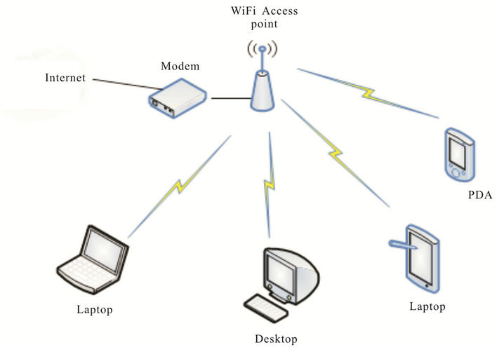
Figure 1. WiFi architecture.
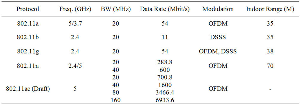
Table 1. Wireless standard of IEEE 802.11 family.
The modulation scheme used in 802.11g is OFDM with Direct Sequence Spread Spectrum (DSSS). Even though 802.11g operates in the same frequency band as 802.11b, it can achieve higher data rates because of its heritage to 802.11a modulation.
2.1.2. 802.11n
802.11n is an amendment which improves upon the previous 802.11 standards by adding MIMO. 802.11n operates in both the 2.4 GHz and the lesser used 5 GHz bands. The IEEE has approved the amendment and it was published in October 2009. Prior to the final ratification, enterprises were already migrating to 802.11n networks based on the WiFi Alliance’s certification of products conforming to a 2007 draft of the 802.11n proposal.
The popularity of WiFi is due to its promising performance. With latest MIMO and OFMD technologies, WiFi signal penetrates through concrete wall easily with a relatively high data transmission speed. Therefore, WiFi is definitely suitable for VBC of WiZBAN. It is pointed out that WiFi does not possesses the smart energy profile and it is inherent fast data rate renders itself more suitable for data aggregation in VBC.
2.2. ZigBee
ZigBee is another WPAN standard of IEEE 802.15.4 [5,6]. It has some common attributes with Bluetooth such as short-range transmission, low cost of production, low data rate and low power consumption. For comparison, ZigBee is more energy conservable than Bluetooth and perfect solution for smaller packets over a large network. The life-span of ZigBee can last for years which are especially suitable to SM and home automation. Operating with over 65,000 devices, a ZigBee network is widely used in home and building automation as well as game and medical sensors.
In ZigBee network architecture as shown in Figure 2, a distinct feature should be heeded. The mesh network guarantees connection to the data’s destination even when a link fails unexpectedly on the way. Figure 3 shows the mesh connections among the sensor nodes forming a network. If two network points are unable to communicate as intended, transmission is dynamically routed from the blocked node to a router with a clear path to the data’s destination.
3. WiZBAN Overview
This section introduces the AMI and explains the role of WiZBAN in supporting AMI services. Generally, AMI (Figure 4) provides end to end metering and DR service which involve three basic AMI elements: the IHD, the smart meter and the utility server. The smart meter measures the energy consumption of an individual user and sends meter readings to the utility server periodically. The utility server stores the meter reading for profiling record and analysis as well as billing purpose. Under critical situations, the utility system takes over (under voluntary agreement) the control of users’ high energy demand appliances such as air conditioner via IHD. As a result, the peak demand of electricity is reduced. The IIHD not only provides the timely consumption and pricing information by interacting with the smart meter but also teams up with other ZigBee home automation devices such as light switches, power outlets, computers and appliances to form a HAN and thus facilitating the aim of home automation and energy management. To
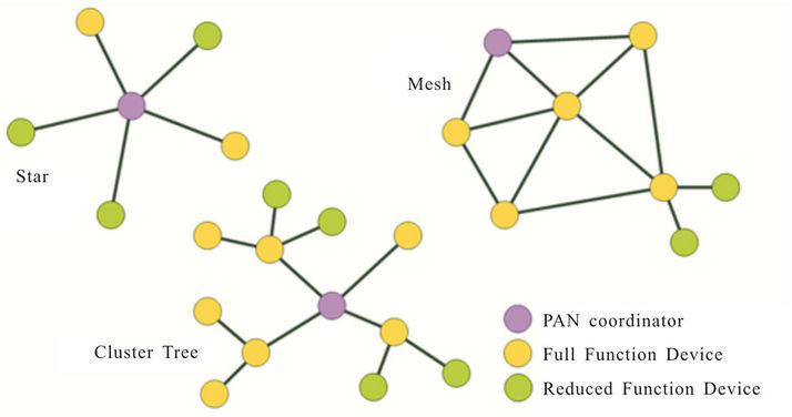
Figure 2. ZigBee architecture.
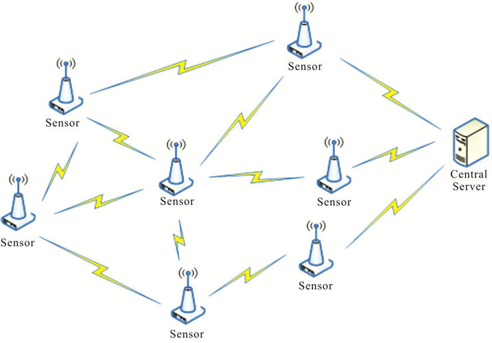
Figure 3. ZigBee mesh network.
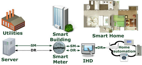
Figure 4. AMI overview.
conduct the DR, the utility server shuts down some appliances in the case of shortage of electricity experienced by the utility, and in such a circumstance, consumers may enjoy a lower energy rate.
To enable the captioned AMI services in high rises, WiZBAN has been developed for intra building communication. Generally, WiZBAN is divided into two parts: VBC (backbone for ordinary AMI) and HFC (mesh floor networks for HAN services). Since the smart meters are centralized in meter rooms which are located on different floors, a WiFi network has been setup for VBC to handle the heavy metering traffic. The WiFi backbone network consists of WiFi ZigBee Gateway (WiZGW) and WiFi ZigBee Meter Hub (WiZMH). WiZGW does not only play the role of BAN GW but also monitors and governs the operation of the WiZMH. By integrating with WiFi access point, WiZGW collects meter readings from WiZMH through the WiFi VBC and WiZMHs are connected to meters using ZigBee communication. On the other hand, WiZGW also provides socket communication interface to the utility server for meter reading collection through an IP network via either a GSM/HSPA device or a Ethernet network. To extend the coverage of WiFi VBC, WiFi Bridge are deployed if deemed necessary. The attention is then drawn to the ZigBee HFC which is a ZigBee network connecting WiFi ZigBee IHD (WiZIHD) and WiZMH. WiZMH is a meeting point of WiFi VBC and ZigBee HFC and it translates both ZigBee and WiFi protocol. With embedded ZigBee coordinator, WiZHM teams up with ZigBee router and WiZIHD to support the real time meter reading service and DR. The overview of WiZBAN is shown in Figure 5.
To gain more insight, attention is drawn to the information system architecture of WiZBAN (Figure 6). The information system architecture consists of the following system components: WiFi ZigBee IHD (WiZIHD), WiFi ZigBee Gateway (WiZGW), WiFi ZigBee Meter Hub (WiZMH), Central Station (CS), Gateway Cluster (GC), Database Cluster (DBC), Administration Server Cluster (ASC), Configuration Client (CC). The functionalities of the components are described as follows:
1) WiFi ZigBee IHD (WiZIHD)
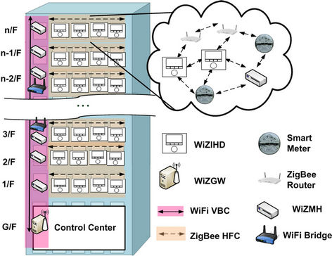
Figure 5. WiZBAN overview.
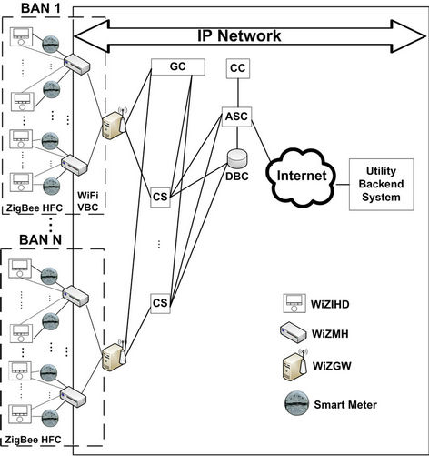
Figure 6. Information system architecture of WiZBAN.
The WiZIHD collects meter readings from WiZMH through ZigBee HFC to provide timely consumption information to the consumer.
2) WiFi ZigBee Meter Hub (WiZMH)
The WiZHM collects meter readings from smart meter via ZigBee communication and sends meter readings to the WiZGW through the WiFi VBC.
3) WiFi ZigBee Gateway (WiZGW)
The WiZGW monitors and governs the operation of the WiZMHs The WiZGW also provides socket communication interface to the CS for meter reading collection through IP network via either a GSM/HSPA device or a Ethernet network.
4) Central Station (CS)
The CS monitors and controls the operation of the DCs. It collects meter readings from the DC through socket communication interface via the IP network. It also provides backup meter data and operation log to the DBC.
5) Gateway Cluster (GC)
The GC provides load-balance communication redirect functionality to establish communication between DCs and CSs. It monitors the operations of CSs, rearranges resources of CS and provides backup operation log to DBC. This is a master-slaves server structure with redundancy to provide high availability.
6) Database Cluster (DBC)
The DBC provides data storage of meter readings, system settings, operation log, and mirroring backup over multiple database servers.
7) Administration Server Cluster (ASC)
The ASC provides administration functionality for system setting/configuration, scheduling, monitoring, and meter readings access for server. This is a master-slaves server structure providing high availability.
8) Configuration Client (CC)
The CC provides user interface system setting/configuration, monitoring and operation scheduling of system devices.
4. Delay Model of WiZBAN
In this section, the delay model of WiZBAN is presented. Since WiZBAN includes ZigBee and WiFi and is supporting two services, the delay incurred betweent he conversion must be known. In this paper, a model accounting for such a delay is developed. The delay model is divided into three sections: ZigBee HFC, WiFi VBC and service. Consider a high rise with Nf floors covering by k WiFi bridges and each floor is divided into Na apartments. Assuming a smart meter stores Nr record for data recovery and the record length is Nb bytes.
4.1. ZigBee HFC
Based on [6,7] the throughput of ZigBee communication, Thbps, is given by:
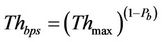 (1)
(1)
where Thmax is the maximum throughput of IEEE 802.15.4 in 2.4 GHz and the probability of Bit Error Rate, Pb, is given by:

where Eb/N0 is the energy per bit to noise power spectral density ratio. The HFC delay for an apartment a, DHFC(a), is given by [6,7]:
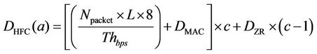 (2)
(2)
where Npacket refers the number of packet; DMAC refers the MAC delay for the CSMA/CA back off; DZR is the average delay of a packet passing through a intermediate ZigBee router, L is the packet length and c is the number of hop between WiZIHD and WiZMH. Therefore, the average HFC delay, DHFC, is obtained as:
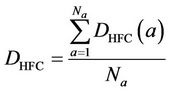 (3)
(3)
4.2. WiFi VBC
Based on [8], the throughput of multi-user WiFi communication, Thmu, is given by
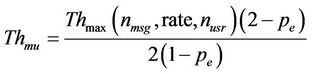 (4)
(4)
where Thmax is the maximum throughput of nusr user IEEE 802.11network transmitting nmsg byte data with Rate Mbps and the packet error probability, pe, is given by:
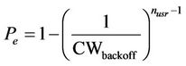 (5)
(5)
where CWbackoff denoted as the mean of contention window depends directly on the number of collision , as it doubles on each packet collision. The RTS/CTS packets are used and so delay for single Transmission, Ds, is given by:
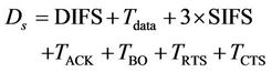 (6)
(6)
where DIFS is Distributed coordination function Interframe Space duration, SIFS (Short Interframe Space), is the small time interval between the data frame and its acknowledgment while Tdata, TACK, TRTS and TCTS are the transmission duration of data packet, acknowledgement packet, ready to send packet and clear to send packet respectively. The general form transmission duration for l byte data (Tl) is given by:
 (7)
(7)
Furthermore, TBO is the back off time that given as:
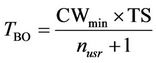 (8)
(8)
where CWmin represents the minimum contention windows and TS (standard WiFi time slot) is 20 μs. The VBC delay for floor f, DVBC(f), with k WiFi bridge is defined as:
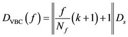 (9)
(9)
And the average VBC delay, DVBC, is obtained as:
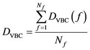 (10)
(10)
4.3. Service
SM and DR are two major services supported by WiZBAN and the performance of WiZBAN is defined in this section. The SM transmission involves meter reading collection from ZigBee meters via WiZMH which then forwards the data to WiZGW via WiFi bridges. Therefore, the SM service delay includes a single hop ZigBee transmission delay and a VBC delay. As a result, the SM service delay for specific fth floor, DSM(f), is defined as:
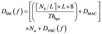 (11)
(11)
The SM service delay for the entire building, DSM, is given as:
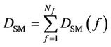 (12)
(12)
On the other hand, the DR involves data transmission from WiZGW to WiZIHD which consists of VBC and HFC. As a result, the DR service delay for apartment a on fth floor, DDR(f,a), is defined as:
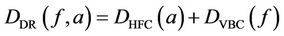 (13)
(13)
5. Performance Evaluation
A case study has been conducted in an existing typical Hong Kong residential high rise building [9] for the design and investigation of the performance of WiZBAN. As shown in Figure 7, the building has 23 floors and each floor hosts 10 residential apartments. Therefore there are altogether 230 meters. Since it is difficult to obtain measured data for the entire building, a small amount of measured results (with best effort) is collected. Based on the measured data, simulation model will be developed to predict the overall network performance (of the whole building). As a result, a simulation OPNET model is developed to project the WiZBAN performance for the entire building (23 floors). OPNET is an accurate model describing the behavior of network performance from physical layer to network layer and is popularly adopted by researchers [10], thus OPNET is also adopted in this investigation.
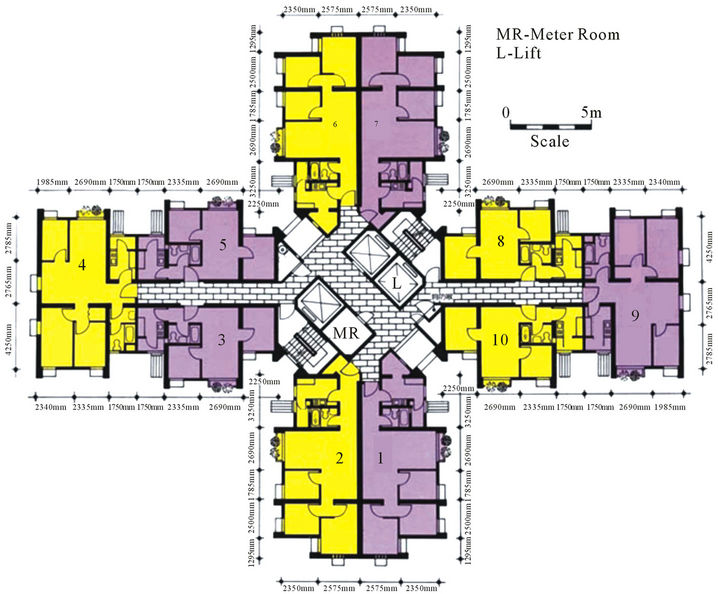
Figure 7. Testing site floor network.
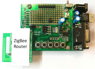
To conduct the onsite investigation, a system prototype of WiZBAN consisting 5 floors has been developed. Since there are ten apartments per floor for these five floors, the following devices were used for measurement: five WiZMHs, one WiZGW, one WiFi Bridge, ten ZigBee routers and ten WiZIHDs. The WiZGW was typical laptop computer connecting with a WiFi access point with internet cable while WiZMH was a laptop computer with a ZigBee USB dongle. The devices and system specification are given in Figure 8 and Table 2 respectively. For valuation purpose, the WiFi network is configured such that the five-floor backbone network (WiFi bridge locates on third floor) and a floor network (locating on the 5th floor, i.e. Nf = 5) forms a single ZigBee mesh network. It is important to pinpoint that the online site investigation aims to verify the practicability of WiZBAN.
This section aims at investigating the service delay of DR and SM. Therefore, two scenarios were setup during the onsite investigation. To investigate the DR service performance, WiZGW was configured to generate DR for every l5 minutes. The WiZIHDs replied the request by sending back a confirmation. After the confirmation was verified, the WiZGW recorded the DR Round Trip Delay (RTD) for the entire process. Five hundred records were monitored (typically 5 days work) in order to provide reliable basis data to smooth out irregularities due to potential inference and other possible factors like temperature and humidity change. The results obtained from the experiment are summarized in Figure 9.
 (a)
(a)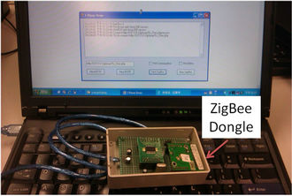 (b)
(b)
Figure 8. WiZBAN system protocol. (a) ZigBee router; (b) WiZMH.
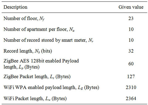
Table 2. System specification of experimental DR-ZBAN.
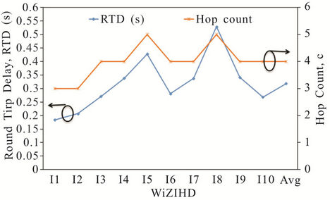
Figure 9. DR service RTD of different apartments for Nf = 5.
Figure 9 gives RTD and hop count, c, between WiZIHDs (I1 - I10) and WiZGW for Nf = 5(on 5th floor). In general, the RTDs are strongly related to c because more hops imply a longer routing path. Among I1 - I10, the values of c of I5 and I8 (i.e. c = 3) are the highest and thus their RTDs are also ranked top two in all scenarios. The discrepancy of RTD I5 and I8 is given by the random back off period (TBO) during the media access which also known as media access delay (DMAC). On the other hand, the lowest two RTDs are recorded from I1 and I2 (~0.2s) because both of them have reached the WiZGW with shortest path (i.e. c = 3). It can be concluded that the floor network design of WiZBAN are practical and the average RTDs of WiZIHDs is 0.32 s for Nf = 5. Attention is drawn to the fact that the discussion up to this point only focuses on the case of the single floor network. Based on the practical floor network design, the DR service delay under different multi-storey buildings are investigated by OPNET simulation. Apart from the DR, SM is another focus of this study. To reflect the real situation and understand the impact of the height of building (the density of traffic) on service delay, five backbone networks were setup for Nf = 1 - 5. The testing network consists of one to five WiZMH(s) and WiZGW (locating in the meter room of ground floor). The WiZGW collected the metering reading from WiZMH by broadcasting MRO requests. WiZMHs then sent all meter reading records to WiZGW. After verifying the received data, the WiZGW recorded the duration of the entire process—this is considered as SM RTD. Such processes were repeated for five hundred times during both experiment and simulation and the average RTDs between the WiZMHs and WiZGW were measured. These experimental result were compared with the simulation results for Nf = 10, 15, 20 and 23. The experimental and simulated results of both SM and DR services are plotted in Figure 10.
Figure 10 investigates the average RTD of SM and DR where Nf = 1 - 23. In general, the average RTD of both SM and DR are found to be directly proportion to the height of building since c (between WiZMH and WiZGW) increase as the height increases. As the result, average RTD increases. The average RTD of SM is longer than DR because average DR RTD is measured for specific apartment while the average SM RTD is referred to the entire building. From Figure 10, the average RTD of SM and DR are projected as 9 s and 0.6 s respectively for the entire testing site (a 23 floor residential building with the floor plan show in Figure 7). By integrating WiFi and ZigBee technology, a total wireless BAN solution, namely WiZBAN, has been successfully developed to support the real time smart grid applications.
6. Conclusion
Advance Metering Infrastructure (AMI) is an initial step for smart grids development which provides a real time service between the end user site and utilities. To extend the use of AMI from the individual home to high rise building (implying high traffics), the concept of Building Area Network (BAN) has been proposed by researchers. In this paper, a WiFi ZigBee hybrid BAN solution, namely WiZBAN, is proposed and implemented to cater
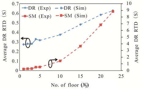
Figure 10. The average RTD of DR and SM service for Nf = 1 - 23.
for fast and efficient deployment of AMI in high traffic area such as high rises It is important to highlight that the major challenge of WiZBAN is to handle the high density environment which results in heavy traffic loading and weak signal propagation. To overcome the captioned problem, Vertical Backbone Communication (VBC) and Horizontal Floor Communication (HFC) are defined for WiZBAN. WiZBAN consists of WiZBAN Gateway (WiZGW), WiZBAN Meter Hub (WiZBAN) and WiZBAN In Home Display (WiZIHD) which caters for the smart grids services like smart metering and demand response. WiZGW is the vital element of WiZBAN to connect WiZBAN to utilities and it teams up with WiZMH to enables VBC. On the hand, WiZMH interacts with smart meters and is the interception point of VBC and HFC. WiZMH also setup the HFC together with WiZIHD to provide the user interface for end users. To shorten the transmission time, WiFi is adopted for VBC while ZigBee is applied for HCF to overcome the weak signal propagation. To understand the performance of WiZBAN, a case study has been conducted based on an existing 23 floor residential building. From the simulated result, average round trip delay of demand response and smart metering are 0.6 s and 9 s respectively.
7. Acknowledgements
The support from Innovation to Realization Funding Scheme with project No. 9666007, CityU Applied Research Grant with project No. 9667063, the Center for Power Electronics, City University of Hong Kong and the Citycom Technology Ltd. are gratefully acknowledged.
REFERENCES
- Y.-H. Jeon, “QoS Requirements for the Smart Grid Communications System,” International Journal of Computer Science and Network Security, Vol. 11, No. 3, 2011, pp. 86-94.
- Y. Simmhan, Q. Zhou and V. K. Prasanna, “Chapter: Semantic Information Integration for Smart Grid Applications,” Green IT: Technologies and Applications, 2011, pp. 361-380.
- Z. M. Fadlullah , M. M. Fouda, N. Kato, A. Takeuchi, N. Iwasaki and Y. Nozaki, “Toward Intelligent Machine-toMachine Communications in Smart Grid,” IEEE Communications Magazine, Vol. 49, No. 4, 2011, pp. 60-65. doi:10.1109/MCOM.2011.5741147
- IEEE Std 802.11, “IEEE Standard for Information Technology-Telecommunications and Information Exchange between Systems-Local and Metropolitan Area Networks-Specific Requirements—Part 11: Wireless LAN Medium Access Control (MAC) and Physical Layer (PHY) Specifications,” 2007.
- IEEE Std 802.15.14, “Wireless Medium Access Control (MAC) and Physical Layer (PHY) Specifications for Low-Rate Wireless Personal Area Networks (LRWPANs),” 2003.
- K. F. Tsang, H. Y. Tung and K. L. Lam, “ZigBee: From Basics to Designs and Applications,” Prentice Hall, Upper Saddle River, 2009.
- K. F. Tsang, “Wireless Communication,” Prentice Hall, Upper Saddle River, 2008.
- M. F. Caetano, P. Vieira, J. L. Bordim and P. S. Barreto, “Throughput Bounds for HTTP Services over WiFi Networks,” International Journal of Computer Science and Network Security, Vol. 10, No. 8, 2010, pp. 13-20.
- T. Y. Chen, J. Burnett and C. K. Chau, “Analysis of Embodied Energy Use in the Residential Building of Hong Kong,” Energy, Vol. 26, No. 4, 2001, pp. 323-340. doi:10.1016/S0360-5442(01)00006-8
- OPNET University Program, 2012. http://www.opnet.com/services/university/