Circuits and Systems
Vol.3 No.2(2012), Article ID:18542,4 pages DOI:10.4236/cs.2012.32023
Low Input and High Output Impedances Current-Mode First-Order Allpass Filter Employing Grounded Passive Components
Department of Electronic Engineering, Chung Yuan Christian University, Chung-Li, Chinese Taipei
Email: *jwhorng@cycu.edu.tw
Received December 26, 2011; revised February 23, 2012; accepted March 2, 2012
Keywords: Second-Generation Current Conveyor; First-Order Filter; Allpass; Current-Mode
ABSTRACT
A current-mode low input and high output impedances first-order allpass filter using two multiple output second-generation current conveyors (MOCCIIs), one grounded capacitor and one grounded resistor is presented. The suggested filter uses a canonical number of passive components without requiring any component matching condition. The frequency responses simulation results of the proposed filter confirm the theoretical analysis.
1. Introduction
Current conveyors (CCs) are receiving much attention for their potential advantages such as inherent wider signal bandwidths, simpler circuitry and larger dynamic range [1,2]. Current-mode active filters with low input impedance and high output impedance are of great interest because they can be directly connected in cascade to implement higher order filters [3,4]. Besides the use of only grounded capacitor and resistor are beneficial from the point of view of integrated circuit fabrications [5,6]. Several current-mode first-order allpass filters using various active components have been reported. Some circuits use two current conveyors to realize such a firstorder allpass filter function with high output impedance [7-9]. However, the passive components they used are not canonical and they require passive components matching conditions [7,8]. Moreover, these circuits [7-9] have not the advantage of low input impedance. The first-order allpass filters [10,11] each uses two current conveyors, one grounded capacitor and one grounded resistor with low input and high output impedances. The first-order allpass filter [12] uses one Z-copy current inverter transconductance amplifier and one grounded capacitor with low input and high output impedances. However, the output terminals of these circuits [10-12] require the connection of two current output terminals. This solution will degrade the final output impedance because of the parallel connection of two individual output impedances [13]. Some first-order allpass circuits each use one active component [14] were presented. However, these circuits require passive matching conditions and the input impedances of are not low. Some first-order circuits use one active element, one capacitor and one resistor [15-17] were presented. However, these circuits have not the advantage of low input impedance. In 2009, a current-mode first-order allpass filter uses one current differencing transconductance amplifier (CDTA) and one grounded capacitor with low input impedance and high output impedance was presented [18]. As the CDTA is equivalent to the circuit composed of two second-generation current conveyors (CCIIs) with a transconductance amplifier [18], the CDTA is a relative complex device with respect to CCII.
In this paper, a new current-mode first-order allpass filter using two multiple output second-generation current conveyors (MOCCIIs), one grounded capacitor and one grounded resistor are presented. The proposed circuit has the advantages of low input and high output impedances and without requiring any element matching condition.
The rest of the paper is presented as follows. In Section 2 we present the proposed current-mode first-order allpass filter circuit. Section 3 discusses the active and passive sensitivities of the proposed filter. Section 4 discusses the influences of parasitic elements on the proposed circuit. The frequency responses simulation results are presented in Section 5. Section 6 concludes the paper.
2. Proposed Circuit
Using standard notation, the port relations of a MOCCII can be characterized by vx = vy, izk = ±ix and iy = 0. Considering the proposed current-mode circuit in Figure 1, the current transfer function can be expressed as
 (1)
(1)
From (1) it can be seen that a first-order allpass response is obtained from Iout. Because the input terminal of the proposed first-order allpass filter is connected directly to the x terminal of MOCCII (1) and the y terminal of MOCCII (1) is grounded, the input terminal has the advantage of low input impedance. Because the Iout output terminal is taken out directly from the z22+ terminal of the MOCCII (2), the Iout output terminal has the advantage of high output impedance. The proposed circuit uses only one grounded resistor and one grounded capacitor, the use of only grounded capacitor and resistor are beneficial from the point of view of integrated circuit fabrications [5,6].
3. Non-Ideality Analysis of the MOCCIIs
Taking into consideration the MOCCII non-idealities, the port relations of MOCCII can be expressed as
 (2)
(2)
where  and
and  denotes the current tracking error,
  and
and  is the input voltage tracking error of a MOCCII. Reanalysis of the filter circuit in Figure 1 yields the following modified transfer functions:
 (3)
(3)
The cutoff frequency is obtained by
 (4)
(4)
The active and passive sensitivities are low and obtained as ;
; .
.
4. Influences of Parasitic Elements
A non-ideal MOCCII model is shown in Figure 2 [19]. It is shown that the real MOCCII has parasitic resistors and capacitors from the y and z terminals to the ground, and also, a series resistor at the input terminal x. Taking into account the non-ideal MOCCIIs and assuming the circuits are working at frequencies much lower than the corner frequencies of  and
and , namely,
 . The transfer functions of Figure 1 become
 (5)
(5)
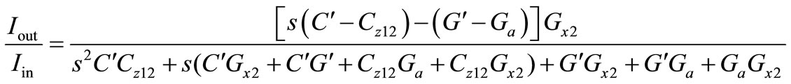
where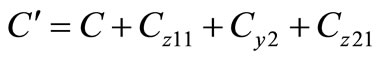 ,
,  ,
,
 .
.
In Equation (5), undesirable factors are yielded by the non-idealities of the MOCCIIs. The effects of capacitance Cz12 become non-negligible at very high frequencies. To minimize the effects of the MOCCIIs’ non-idealities, the operation angular frequency should restricted to the following condition
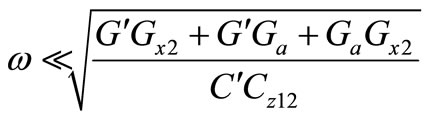 (6)
(6)
5. Simulation Results
HSPICE simulations were carried out to demonstrate the feasibility of the proposed circuit in Figure 1 using 0.18 μm, level 49 MOSFET from TSMC. The MOCCII was realized by the CMOS implementation in Figure 3 [20] with the NMOS and PMOS transistor aspect ratios W/L = 4.5 u/0.9 u and W/L = 9 u/0.9 u, respectively.
Figure 4 represents the magnitude and phase responses of the first-order allpass filters, designed with fc = 3.979 MHz: C = 10 pF and R = 4 kΩ. The power supply was ±1.25 V. The bias voltages are Vb = –0.6 V.

Figure 1. The proposed current-mode first-order filter.
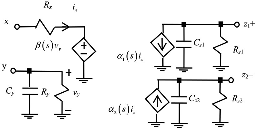
Figure 2. The non-ideal MOCCII model.

Figure 3. The CMOS MOCCII implementation.

Figure 4. Simulation results of the proposed current-mode first-order allpass filter.
6. Conclusion
A new current-mode first-order filter configuration using two MOCCIIs, one grounded capacitor and one grounded resistor is presented. The proposed circuit has the advantages of low input and high output impedances, using grounded passive components and without requiring any element matching condition.
REFERENCES
- C. Toumazou, F. J. Lidgey and D. G. Haigh, “Analog IC Design: The Current-Mode Approach,” Peter Peregrinus, London, 1990.
- J. W. Horng, Z. R. Wang and C. C. Liu, “Voltage-Mode Lowpass, Bandpass and Notch Filters Using Three PlusType CCIIs,” Circuits and Systems, Vol. 2, No. 1, 2011, pp. 34-37. doi:10.4236/cs.2011.21006
- A. M. Soliman, “Current Mode Universal Filter,” Electronics Letters, Vol. 31, No. 17, 1995, pp. 1420-1421. doi:10.1049/el:19951018
- J. W. Horng, “Current-Mode and Transimpedance-Mode Universal Biquadratic Filter Using Multiple Outputs CCIIs,” Indian Journal of Engineering & Materials Sciences, Vol. 17, No. 3, 2010, pp. 169-174.
- M. Bhushan and R. W. Newcomb, “Grounding of Capacitors in Integrated Circuits,” Electronic Letters, Vol. 3, No. 4, 1967, pp. 148-149. doi:10.1049/el:19670114
- S. Minaei and E. Yuce, “All-Grounded Passive Elements Voltage-Mode DVCC-Based Universal Filters,” Circuits, Systems, and Signal Processing, Vol. 29, No. 2, 2010, pp. 295-309. doi:10.1007/s00034-009-9136-1
- J. W. Horng, C. L. Hou, C. M. Chang, W. Y. Chung, H. L. Liu and C. T. Lin, “High Output Impedance Current-Mode First-Order Allpass Networks with Four Grounded Components and Two CCIIs,” International Journal of Electronics, Vol. 93, No. 9, 2006, pp. 613-621. doi:10.1080/00207210600711580
- B. Metin, K. Pal and O. Ciceloglu, “All-Pass Filter for Rich Cascadability Options Easy IC Implementation and Tenability,” International Journal of Electronics, Vol. 94, No. 11, 2007, pp. 1037-1045. doi:10.1080/00207210701763589
- I. A. Khan, P. Beg and M. T. Ahmed, “First-Order Current Mode Filters and Multiphase Sinusoidal Oscillators Using CMOS MOCCIIs,” The Arabian Journal for Science and Engineering, Vol. 32, No. 2C, 2007, pp. 119- 126.
- S. Maheshwari, “Novel Cascadable Current-Mode First Order All-Pass Sections,” International Journal of Electronics, Vol. 94, No. 11, 2007, pp. 995-1003. doi:10.1080/00207210701751238
- S. M. Al-Shahrani, “CMOS Wideband Auto-Tuning Phase Shifter Circuit,” Electronics Letters, Vol. 43, No. 15, 2007, pp. 14-15. doi:10.1049/el:20070284
- D. Biolek and V. Biolkova, “Allpass Filter Employing One Grounded Capacitor and One Active Element,” Electronics Letters, Vol. 45, No. 16, 2009, pp. 807-808. doi:10.1049/el.2009.0575
- J. W. Horng, “High Output Impedance Current-Mode Universal Biquadratic Filters with Five Inputs Using Multi-Output CCIIs,” Microelectronics Journal, Vol. 42, No. 5, 2011, pp. 693-700. doi:10.1016/j.mejo.2011.02.007
- S. Minaei and M. A. Ibrahim, “General Configuration for Realizing Current-Mode First-Order All-Pass Filter Using DVCC,” International Journal of Electronics, Vol. 92, No. 6, 2005, pp. 347-356. doi:10.1080/00207210412331334798
- A. Toker, S. Ozoguz, O. Cicekoglu and C. Acar, “Current-Mode All-Pass Filters Using Current Differencing Buffered Amplifier and a New High-Q Bandpass Filter Configuration,” IEEE Transactions on Circuits and Systems-II: Analog and Digital Signal Processing, Vol. 47, No. 9, 2000, pp. 949-954.
- S. Kilinc and U. Cam, “Current-Mode First-Order AllPass Filter Employing Single Current Operational Amplifier,” Analog Integrated Circuits and Signal Processing, Vol. 41, No. 1, 2004, pp. 47-53. doi:10.1023/B:ALOG.0000038282.60137.5f
- S. Maheshwari, “A New Current-Mode Current-Controlled All-Pass Section,” Journal of Circuits, Systems, and Computers, Vol. 16, No. 2, 2007, pp. 181-189. doi:10.1142/S0218126607003599
- A. Lahiri and A. Chowdhury, “A Novel First-Order Current-Mode All-Pass Filter Using CDTA,” Radioengineering, Vol. 18, No. 3, 2009, pp. 300-305.
- E. Yuce, “Grounded Inductor Simulators with Improved Low-frequency Performances,” IEEE Transactions on Instrumentation and Measurement, Vol. 57, No. 5, 2008, pp. 1079-1084. doi:10.1109/TIM.2007.913822
- W. Surakampontorm, V. Riewruja, K. Kumwachara and K. Dejhan, “Accurate CMOS-Based Current Conveyors,” IEEE Transactions on Instrumentation and Measurement, Vol. 40, No. 4, 1991, pp. 699-702. doi:10.1109/19.85337
NOTES
*Corresponding author.