Journal of Electromagnetic Analysis and Applications
Vol. 1 No. 3 (2009) , Article ID: 728 , 6 pages DOI:10.4236/jemaa.2009.13027
Effect of Warm Ionized Plasma Medium on Radiation Properties of Mismatched Microstrip Termination
Physics Department, College of Science, King Faisal University, Saudi Arabia.
Email: drswalha@hotmail.com
Received April 14th, 2009; revised July 13th, 2009; accepted August 2nd, 2009.
Keywords: Mismatched Termination, Open Circuit Discontinuity, Matched Microstrip Termination, Ionized Plasma
ABSTRACT
Study of radiation properties of mismatched microstrip termination is carried out in warm ionized electron plasma medium. Linearised hydrodynamic theory coupled with vector wave technique is used to investigate radiation patterns and radiated power of a microstrip mismatched termination in one component electron plasma media for different plasma to source frequencies .These properties are used to compare the performance of an open circuit discontinuity with those of matched microstrip termination. Matched terminations are found more suitable for applications at higher frequencies than an open circuit discontinuity in the plasma medium though in free space they are less suitable.
1. Introduction
Microstrip antenna has proven to be an effective, light weight and quite inexpensive radiator for aerospace vehicles [1]. Many workers have reported radiation properties of different microstrip radiators in free space [2–4]. Metallic and dielectric losses, breakdown effect at higher power level and radiations from discontinuities, however, limits the application of a microstrip line structure over the ground plane [5]. Radiations from microstrip discontinuity become quite dominant at microwave frequencies and hence become major limiting factor. Hence, it is always necessary to control them somehow. Radiations from an open circuit microstrip discontinuities are investigated recently [6] in an ionized plasma medium of infinite thickness. Radiations from a mismatched termination in an ionized plasma medium are investigated in this communication. Using these relations, performance of two other types of discontinuities viz. a matched microstrip termination and an open circuit microstrip termination are investigated in free space as well as in ionized hot plasma medium.
In strip line structure, field does not lie uniformly in between the conducting patch and the ground plane but some fringe fields leak in the air near the edges of the strip. Dielectric polarization beneath the strip takes place which gives rise to the polarization current in addition to the already existing strip current [5]. Considering both these currents together, radiation patterns and radiated power by a mismatched termination are obtained for different plasma to source frequency . With the presence of an actual ionized plasma medium, effective permittivity of structure changes marginally in comparison to the effective permittivity in free space and hence resonance frequency also changes marginally [7]. It is found that percent deviation in frequency is about 0.003% in the presence of an ionized plasma media of infinite thickness which dose not affects predicted results seriously.
2. Radiation Field Expressions
The geometry and coordinate system of a mismatched microstrip termination is shown in Figure 1.
A strip line above the ground plane is located along the z-axis of the coordinate system. The thickness of the dielectric substrate is considered to be  , width of strip
 ,relative permeability and permittivity
  and
and  respectively.
It is considered here that the termination mismatches the strip. Far fields are obtained by considering a magnetic current density alone with a perfect electric current condition.
For strip line configuration, the integration to find electric field using vector potential is carried out over a cross section which gives a combination of currents formed by polarization current ( along x-axis) and a strip current (along z-axis).
Let the strip current be
 (1)
(1)
where
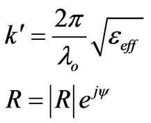
 is the wavelength in free space,
  is the effective dielectric constant of substrate material,
  is the reflection coefficient at the end of the line and its limiting value lies in between 0 and 1, and
  is the phase angle between the incident wave and the reflected wave.
Assuming current amplitude is to be constant a cross the strip line, the surface current density in z-direction for end fed line will become
 (2)
(2)
The polarization current density in x-direction will be
 (3)
(3)
where  and
and  are unit vectors in the x and z direction respectively and
  is the actual dielectric constant of the substrate material.
Considering the presence of both these currents together and following the method of [8], the expressions for the radiation patterns are obtained in electromagnetic mode as well as in electroacoustic mode.
These expressions are:
2.1 In Electromagnetic Mode
 (4)
(4)
 (5)
(5)

Figure 1. The geometry and coordinate system of a mismatched microstrip termination
where:


 is the propagation constant in electromagnetic mode.
 is the propagation constant in free space (radian/m)
 is the angular plasma frequency (
 )
)
 is the angular source frequency (
 )
)
2.2 In Electroacoustic Mode
 (6)
(6)
where


Figure 2.  radiation patterns for
  and
and  ,
, 
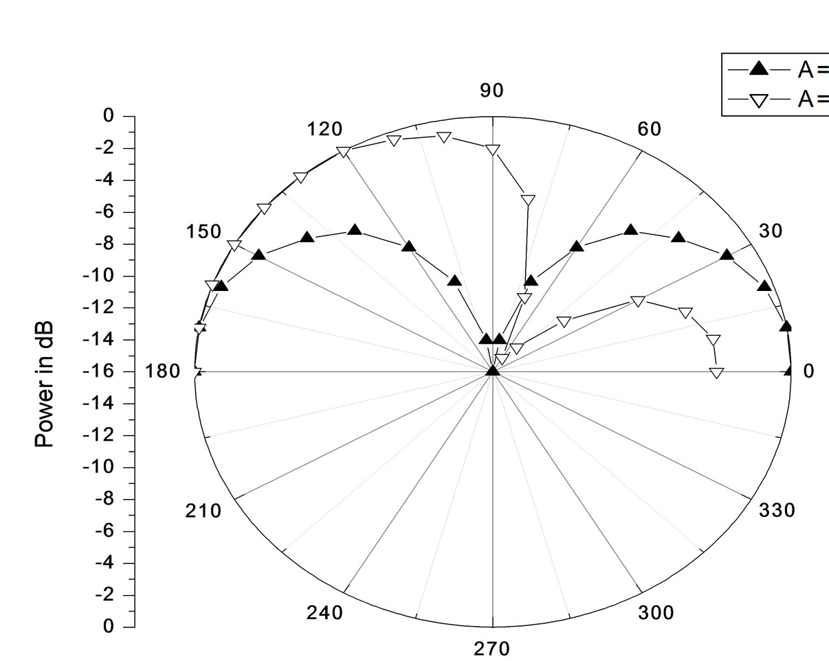
Figure 3.  radiation patterns for
  and
and  ,
, 
 : is the propagation constant in plasma mode.
These value of ,
, and
and  are computed and plotted in Figures (2–4) for two different values of plasma to source frequency. Computations are carried out for
 ,
, 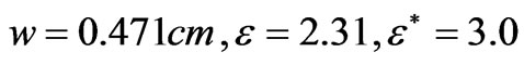 , operation frequency = 1.2GHz ,
  and
and .
.
 Patterns in free space
  are almost uniform. Radiation intensity in the end fire direction
  is slightly more than the radiation intensity in the broadside direction
 . On increasing plasma to source frequency
 , radiation pattern modifies drastically and direction of maximum intensity shifts

Figure 4.  radiation pattern in plasma for
 ,
, 

Table 1. 3dB beamwidth in  and
and  planes for
  and
and 
from  to
to  direction and minimum appears at
 . Almost similar behaviors appear for
  patterns. These patterns in the free space
  are almost symmetric in all the four quadrants, but for higher plasma to source frequency value
 , the 3dB beam width in
  direction is much smaller than in
  direction.
 radiation patterns indicate that only one lobe ap pears in the
  to
to  range. One substituting
  and
and  all the expressions obtained for mismatched microstrip termination reduce immediately to those of open circuit microstrip discontinuity [6]. Similarly on substituting
  and
and , expressions for microstrip matched termination can be obtained [8].
3. Radiated Power
The power radiated by the microstrip mismatched termination through upper half space is obtained by using Poynting vector. For different values of plasma to source frequencies, expressions for radiated power are obtained by using the method of [8].These expressions are:
3.1 For Electromagnetic Mode
 (7)
(7)
where

And

and the radiation resistance in electromagnetic mode
 can be defined as
 (8)
(8)
3.2 For Electroacoustic Mode
 (9)
(9)
and the radiation resistance in plasma mode  can be defined as

These values of  and
and  are computed and plotte for different values of plasma to source frequencies in Figure 5.In the electromagnetic mode, power radiated in free space (
 ) is maximum but decreases on increasing plasma to source frequency. On the other hand, plasma mode field patterns give a quasi periodic pattern. Initially, radiated power in plasma mode is less than the radiated power in electromagnetic mode but it over takes in between the range
 .
.
During the voyage in free space, aerospace vehicle interacts with plasma media and radiates electroacoustic waves in addition to the usual electromagnetic waves. Presence of the electroacoustic wave is mainly responsible for such variation in this plasma media.
It is evident from the expressions of radiated power that they are a function of reflection coefficient. The variations of radiated power in free space  or
or  and in plasma media
  are presented for both electromagnetic mode and longitudinal plasma mode in Figure 6.
In free space  ,radiated power in electromagnetic mode is maximum for
  (matched termination).As mismatch increases, radiated power decreases and becomes minimum at
 .Thereafter it becomes almost uniform up to
 (open circuit microstrip termination).On increasing the plasma to source frequency
 , the radiated power by a matched termination becomes quite small in comparison to its free space value
 . On increasing
  value, radiated power in electromagnetic mode increases continuously but it always remains less than the free space value even for an open circuit termination(
 ).
).
In longitudinal plasma mode, radiated power at  for a matched termination
  is low but increases continuously up to
  (open circuit termination). The total power radiated
  in free space
  is low for an open circuit termination.
4. Conclusions
Effect of the presence of plasma medium on the different discontinuities is observed here by considering different plasma to source frequency  values.
It can be concluded from the present study that for operation in free space an open circuit discontinuity better than a matched termination operating at very high frequencies. In the plasma media, matched termination is
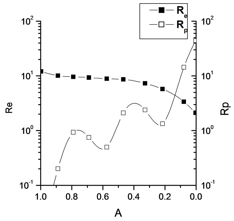
Figure 5. Radiation resistance in EM mode and in plasma mode for different A and 

Figure 6.  and
and  for different values of
  and
and 
better than an open circuit discontinuity because total radiated power is less for matched termination than an open ended termination. More radiations from any discontinuity cause less utility of that structure. Hence, a matched termination is suitable with an antenna in plasma media though open circuit discontinuity suits more in free space. A theoretical effort is made here in this communication which requires experimental verification, though simulation of plasma media in laboratory is very difficult.
REFERENCES
- R. E. Post and D. T. Stephenson, IEEE Transactions, AP P–29,129 P–133, 1981.
- J. R. James and G. J. Wilson, Microwave option and acoustics, 1,165 P–174, 1974.
- K. R. Carver and J. W. Mink, IEEE Transactions, AP–29, 1024, 1981.
- A. G. Derneryd, IEEE Transactions, AP–24,846–851, 1976.
- M. D. Abouzahra and L. Lewin, IEEE Transactions, MTT P–27,722 P–723, 1979.
- D. Bhatnagar, Journal of Inst. Electronic and Telecom. Engrs. 38, 13 P–16, 1992.
- M. V. Schneider, Bell System Tech. J. 48, 1421 P–1444. 1969.
- A. M. Salem, D. Bhatnagar, J.of Plasma Physics, Vol.56, Pt.1, 25 P–34, 1996.