Engineering
Vol. 4 No. 2 (2012) , Article ID: 17433 , 7 pages DOI:10.4236/eng.2012.42015
A New Model for Transmission Network Expansion and Reactive Power Planning in a Deregulated Environment
1Department of Electrical Engineering, Anar Branch, Islamic Azad University, Anar, Iran
2Department of Electrical Engineering, Shahid Bahonar University of Kerman, Kerman, Iran
Email: *a.1366.m@gmail.com
Received October 24, 2011; revised January 20, 2012; accepted January 27, 2012
Keywords: Transmission Expansion Planning; Reactive Power Planning; Load Curtailment; Non-Convex Optimization
ABSTRACT
Transmission network expansion planning (TNEP) is a challenging issue especially in new restructured electricity markets environment. TNEP can be incorporated with reactive power planning in which the operating conditions will be satisfied. In this paper a combinatorial mathematical model has been presented to solve transmission expansion and reactive power planning problem (TEPRPP) simultaneously. The proposed model is a non-convex problem having a mixed integer nonlinear nature where the number of candidate solutions to be evaluated increases exponentially according to the system size. The objective function of TEPRPP comprises the new circuits’ investment and production costs as well as load curtailment penalty payments. A real genetic algorithm (RGA) aimed to obtaining a significant quality solution to handle such a complicated problem has been employed. An interior point method (IPM) is applied to solve the proposed concurrent optimization problem in the solution steps of TEPRPP model. This paper proposes a new methodology for the best location as well as the capacity of VAr sources; it is tested on two well-known systems; the Garver and IEEE 24-bus systems. The obtained results show the capability and the viability of the proposed TEPRPP model incorporating operating conditions.
1. Introduction
As the electricity consumption grows rapidly, new transmission lines are necessary to provide alternative paths for power transfer from power plants to load centers enabling continuous supply. Transmission expansion planning (TEP) has been researched for a long time [1], while the earlier well cited work is developed by Garver [2]. Albeit, most of these studies only consider simplified models like: transportation models (TM), hybrid models (HM), linear disjunctive model (LDM) and DC model [3]. Recently an accurate AC network modeling has been proposed in [4]. The use of the complete AC model in the first phase is incipient but there are few technical literatures on the subject [4-6]. Owing to the large-scale nature of a transmission system and its complexities, TEP has always been a complex non-convex optimization problem. Developing a TEP model considering operating conditions seems to be desired for better power systems utilization. In this regard, reactive power sources are desired for: increasing power transfer, improving power factor, reducing real power losses, and maintaining voltage profile in a permissible range. Thus, TEP and reactive power planning (RPP) are crucial issues especially in modern power systems. The objective of the simultaneous transmission expansion and reactive power planning problem, referred to as TEPRPP. In fact, it is to determine “where”, “how many” and “when” new devices such as transmission lines and reactive power sources must be added to an existing network in order to make its performance viable for a pre-defined horizon of planning at minimum total costs. The benchmark network of the base year, the candidate lines and candidate load buses to install reactive sources, the power generation and power demand in a planning horizon associated with the investment constraints are the basic data for such combinatorial problem. In regulated power market TEPRPP can be formulated as a large-scale mixed-integer nonlinear optimization problem. Various optimization techniques have been used to solve such a crucial problem. These methods are classified as classical optimization techniques [7,8] as well as meta-heuristics such as Simulated Annealing [9], Genetic Algorithms [10], Tabu Search [11] and Greedy Randomized Adaptive Search Procedure (GRASP) [12].
On the other hand, electricity industry restructuring in recent years has resulted in the separation of generation and transmission systems and the introduction of competitive power markets. Restructuring and deregulation has exposed transmission planner to new objectives and uncertainties. Therefore, new criteria and approaches are needed for transmission planning in deregulated environments. Two main issues can be emphasized for the differences between planning in regulated and deregulated environment from view point of transmission planners. 1) The objectives of TEP in deregulated power systems differ from those of the regulated ones; 2) The uncertainties in deregulated power systems are much more than in regulated ones [13]. The main objective of TEP in deregulated power systems is to provide a nondiscriminatory and competitive environment for all stakeholders, while maintaining desired power systems reliability. TEP affects the interests of market participants unequally and this should be considered in transmission planning. The objective of the market-based TEP problem is to optimize the transmission network topology by selecting the new circuits that should be added to an existing transmission network so as to minimize the overall generation and transmission costs. It is subjected to operating conditions for generating units and transmission network. In order to establish an effective and efficient TEP, this paper considers lines as well as reactive sources investment costs, load curtailment penalties, and real power generation costs to reform transmission planning model under a deregulated environment. The proposed model is more complicated than traditional model addressed in literature, therefore a real genetic algorithm (RGA) is used to solve TEPRPP via an AC model. It should be notified that an interior point method (IPM) is employed to solve NLP problems that must be solved during the solution steps of RGA.
2. TEPRPP Mathematical Model
TEPRPP problem is usually refers as a static transmission model, while the most often used mathematic formulation for a static TEPRPP is formulated as a mixed integer nonlinear optimization problem as shown below.
 (1)
(1)
 (2)
(2)
s.t.
 (3)
(3)
 (4)
(4)
 (5)
(5)
 (6)
(6)
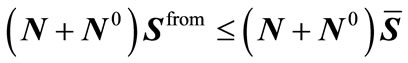
 (7)
(7)
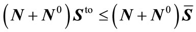
 (8)
(8)
 (9)
(9)
 (10)
(10)
 (11)
(11)
where: c and n represent the circuit costs’ vector and the added lines’ vector, respectively. N and  are diagonal matrices containing the integer-valued vector n and the existing circuits in the base configuration, respectively.
  is the cost function of reactive power (VAr) sources, q is the MVAr size of VAr sources vector. u is the binary vector that indicates whether to install reactive power sources at load buses or not and has integer value.
  is the investment due to adding new circuits to the network and
  is the costs of VAr sources.
  is a vector containing the maximum number of circuits that can be added.
  is the unbounded phase angle vector, while
  and
and  are the existing real and reactive power generation vectors. Similarly,
  and
and  are the real and reactive power demand vectors;
  is the voltage magnitude vector;
 ,
,  and
and  are the vectors of maximum real and reactive power generation limits and voltage magnitudes, respectively; and
 ,
,  and
and  are the vectors of minimum real and reactive power generation limits and voltage magnitudes. In this paper 105% and 95% of the nominal value are used for the maximum and minimum voltage magnitude limits, respectively.
 ,
,  and
and  are the apparent power flow vectors (MVA) through the branches in both terminals and their limits. The first objective function considers only the expansion costs of transmission lines while the second objective function considers the minimum costs of VAR sources that can be installed. The limits for real and reactive power in the generators are expressed by Equations (5) and (6) respectively; and for VAr sources by (7) while voltage magnitudes are restricted by (8). Capacity limits (MVA) of the line flows are presented by (9) and (10), while capacity constraints of the newly added circuits are shown by (11). The costs of VAR sources can be defined as follows:
 (12)
(12)
where:  represents the load buses,
  is the set of all load buses; and
  and
and  are the installation costs and unit costs for a VAr source at bus k.
  is the MVAr size of a VAr source installed at bus k and
  is a binary variable that indicates whether to install reactive power source at bus k or not. Equations (3) and (4) represent the conventional equations of AC power flow considering n, the number of circuits (lines and transformers), and q, the size of VAr sources treated as variables. Due to deregulation of power markets, the general TEP model that only considers the investment costs may not be suitable to the new environment of power markets. Thus a new TEPRPP model needs to take the advantage of deregulated environment incorporating investment costs, load curtailment penalties, and real power generating costs.
3. Proposed TEPRPP Mathematical Model
This section provides a new mathematical model for the TEPRPP problem in a deregulated environment. The optimization model is a mixed-integer nonlinear programming problem that identifies the optimum solution among tradeoffs between production costs, transmission investments and load curtailment costs. Given the network topology, network devices parameters (e.g. line resistance, reactance and suseptance), generators’ data (e.g. capacities and costs) and projected system load levels, the OPF can provide: the voltage profiles of all nodes, the power flows of all transmission lines, and the power outputs of all generators. In other words, OPF calculation determines how generators and the transmission network should be operated to satisfy the operational constraints of the network.
The objective function of the new TEPRPP is the summation of the costs of new lines and VAr source investment, real power generation as well as load curtailment costs. The objective function is expressed as follows:
 (13)
(13)
where: T represents total costs; L represents the cost of load curtailment; G represents production costs under the optimal dispatching conditions; and I represents the investment costs that is summation of line investment and VAr sources investment.
Investment cost is determined as the total expansion investment over the planning period formulated by Equation (14).
 (14)
(14)
Real power generation costs is assumed in a quadratic form that is shown by Equation (15).
 (15)
(15)
where:  represents the real power generation of the generator on bus i;
 ,
,  and
and  are the constant coefficients of power generation; n is number of generators. Costs of load curtailment depend on the electricity price in a time of use (TOU) fashion. In Europe, it is usually assumed to be 30 - 60 times the regular electricity price [14], where for the sake of conservation in this paper it is assumed almost 10 times of electricity price.
Equations (3) and (4) that represented the conventional equations of AC power flow must be reform as follow:
 (16)
(16)
 (17)
(17)
Here,  and
and  are active and reactive load curtailment.
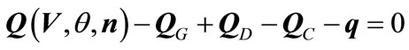
In the proposed model the additional constraints are the following real and reactive power limitations.
 (18)
(18)
 (19)
(19)
The elements of vectors  and
and  are determined by Equations (20) and (21) respectively.
 (20)
(20)
 (21)
(21)
where  represent buses and
  is the set of all buses,
  represents the circuit between buses i and j and
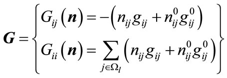
  is the difference in phase angle between buses i and j. The elements of the bus admittance matrix (G and B) are:
 (22)
(22)
 (23)
(23)
Here,  ,
,  and
and  are the conductance, susceptance and shunt susceptance of the transmission line or transformer ij (if ij is a transformer
 ), respecttively; and
  is the shunt susceptance at bus i, while the proposed model does not consider the phase shifters. Elements (ij) of vectors
  and
and  of (9) and (10) are given by the following relationship:
 (24)
(24)
 (25)
(25)
 (26)
(26)
 (27)
(27)
 (28)
(28)
 (29)
(29)
The integer vector variable n, i.e. the number of circuits added in branch ij, and the binary variable u, that shows the connection or disconnection of VAr sources to a load bus, are the most important decision variables such that any feasible production solution of power system depends on their values.
The proposed algorithm is implemented in the AMPL (A Modeling Language for Mathematical Programming) platform. AMPL is a language for large scale mathematical programming and optimization in many applications such as production, distribution, scheduling and etc [15]. To solve TEPRPP problem, an RGA code is developed in AMPL platform that is shown in Figure 1.
Different steps to find the optimum solution is as follows, while the details of RGA used here are in [5].
1) Read network data including: candidate lines and candidate buses for VAr sources.
2) Initialize first generation randomly; each individual is chosen at random. The individuals are represented by a vector consists of number of new lines that are proposed to be added to respective branches. Each member (gene) of this vector may vary from zero to the maximum number of lines.
3) Feasibility checking; each chromosome is checked

Figure 1. Flow diagram of the optimization.
in terms of cost, while those individuals that their investments are too high will be pruned.
4) AC optimal power flow with generation costs and reactive power investment is solved via Interior Point Method [6].
5) The results of OPF are used to calculate the RGA fitness function.
6) When OPF is solved for the entire set of individuals; selection, recombination and mutation are carried out ar new generation is constructed. If all individuals are the same and there is no new individual, the process can be stopped.
4. Illustrative Tests
For the sake of methodology implementation two general test systems; The Garver system and IEEE 24-bus system; were simulated. In this study a fixed cost of c0 = 1000$ and 3 $/KVAr is assumed as a variable cost of VAr source [3] while the penalty of load curtailment is assumed 150 $/MW-h [16]. For better comparison the cost of power losses 1500 $/KW is assumed [17].
4.1. Garver System
The Garver system has 6 buses and 15 branch candidates, the total demand is 760 MW, 152 MVAr and a maximum 5 lines can be added to each branch [4]. Table 1 shows generation cost functions for Garver system. Figure 2 shows the single line diagram of the Garver system.
The planning process resulted in a line investment of 110 million$ and the following lines are added: n2-6 = 1, n3-5 = 1, n4-6 = 2. The total active power losses is 14.15 MW and a total 183.63 MVAr reactive power source must be installed at buses 2, 4 and 5. Tables 2 and 3 show a comparison between the results of the proposed model and the results addressed in literature [4].
4.2. IEEE 24-Bus System
This system has 24 buses, 41 circuits [4]. The single line diagram of IEEE 24-bus system is shown in Figure 3 and Table 4 show the generation data. The results in Table 5 show that 9 reactive sources should be installed at different load buses while the following lines will be added: n1-5 = 1, n6-10 = 1, n7-8 = 2 to the present topology. The line investment cost is $70 million and the Invest-

Table 1. Quadratic generation cost functions.

Figure 2. Single line diagram of the garver system.

Table 2. Results of the proposed model for the garver system.

Table 3. Cost comparison for the garver system (million $).
ment cost of reactive power sources is about $ 5.894 million. By comparing these results with those reported from model in [4] that is shown in Table 6, the average investment cost of the transmission lines and production cost decreases significantly. As it can be seen, power losses increases because in this study power losses is not considered as a term in objective function while generally any change in power generation pattern may

Figure 3. IEEE 24-bus system.

Table 4. Quadratic generation cost function.
change the trajectory of power flow that may have a severe impact on real power losses. Despite the fact that power losses is increased but total costs has been decreased significantly.
5. Conclusion
Traditional transmission expansion planning needs be revised to become more suitable to deregulated environment, hence in this paper, a new model to solve TEPRPP

Table 5. Results of proposed model and traditional model for IEEE 24-bus system.

Table 6. Cost comparison for 24-bus system (million $).
problem under deregulated environment was presented. The fitness function of proposed model is related to the new transmission line investment, the costs of VAr sources associated with production cost and cost of load curtailment. Due to the complexity of this formulation, a real genetic algorithm is utilized to solve TEPRPP problems based on AC models. Moreover, an Interior Point Method (IPM) is applied to solve an OPF as a Non Linear Programming (NLP) during the solution steps of the RGA. The main contribution of this model is to handle TEP and RPP simultaneously in deregulated market, where it can achieve a better solution in comparison with traditional model. The proposed TEPRPP model is tested on two well-known systems: Garver and IEEE 24-bus. The obtained results show significant performance and robustness of the proposed model. Results from different case studies are compared with the results presented in [4], which is one of the major references available at the time of this research. In this paper it has also been shown that by implementing the proposed model, the total costs of investment and production cost can be decreased significantly. On the other hand, the economic evaluations of the results show a significant saving in terms of total investment.
REFERENCES
- G. Latorre, R. D. Cruz, J. M. Areiza and A. Villegas, “Classification of Publication and Models on Transmission Expansion Planning,” IEEE Transaction on Power Systems, Vol. 18, No. 2, 2003 , pp. 938-946. doi:10.1109/TPWRS.2003.811168
- L. L. Garver, “Transmission Network Estimation Using Linear Programming,” IEEE Transaction on Power Systems, Vol. 89, No. 8, 1970, pp. 2025-2034 .
- R. Romero, A. Monticelli, A. Garcia and S. Haffner, “Test Systems and Mathematical Models for Transmission Network Expansion planning,” IEE Proceedings— Generation, Transmission and Distribution, Vol. 149, No. 1, 2002, pp. 27-36. doi:10.1049/ip-gtd:20020026
- M. J. Rider, A. V. Garcia and R. Romero, “Power System Transmission Network Expansion Planning Using AC Model,” IEE Proceedings—Generation, Transmission and Distribution, Vol. 1, No. 5, 2007, pp. 731-742. doi:10.1049/iet-gtd:20060465
- M. Rahmani, M. Rashidinejad and R. Romero, “Efficient Method for AC Transmission Network Expansion Planning,” Electric Power System Research, Vol. 80, No. 9, 2010, pp. 1056-1064. doi:10.1016/j.epsr.2010.01.012
- A. Mahmoudabadi, M. Rashidinejad, M. Mohammadian, M. Zeinaddini-Maymand, M. Rahmani and H. Khorasani, “An Application of CHA to Concurrent Short-Term Transmission Expansion & Reactive Power Planning,” IEEE Powertech Conference, Trondheim, 19-23 June 2011, pp. 1-6.
- S. Binato, M. V. F. Pereira and S. Granville, “A New Benders Decomposition Approach to Solve Power Transmission Network Design Problems,” IEEE Transaction on Power Systems, Vol. 16, No. 2, 2001, pp. 373-380.
- R. Romero and A. Monticelli, “A Hierarchical Decomposition Approach for Transmission Network Expansion Planning,” IEEE Transaction on Power Systems, Vol. 9, No. 1, 1994, pp. 373-380. doi:10.1109/59.317588
- R. A. Gallego, A. B. Alves, A. Monticelli and R. Romero, “Parallel Simulated Annealing Applied to Long Term Transmission Network Expansion Planning,” IEEE Transaction on Power Systems, Vol. 12, No. 1, 1997, pp. 181- 188.
- R. A. Gallego, A. Monteicelli and R. Romero, “Transmission Systems Expansion Planning by Extended Genetic Algorithms,” IEE Proceedings—Generation, Transmission and Distribution, Vol. 145, No. 3, 1998, pp. 329- 335. doi:10.1049/ip-gtd:19981895
- E. L. Da Silva, J. M. A. Orteiz, G. C. De Oliveira and S. Binato, “Transmission Network Expansion Planning under a Tabu Search Approach,” IEEE Transaction on Power Systems, Vol. 16, No. 1, 2001, pp. 62-68. doi:10.1109/59.910782
- S. Binato, G. C. De Oliveira, et al., “A Greedy Randomized Adaptive Search Procedure for Transmission Expansion Planning,” IEEE Transaction on Power Systems, Vol. 16, No. 2, 2001, PP. 247-253.
- P. Georgilakis, C. Karytsas and P. G. Vernados, “Genetic Algorithm Solution to the Market-Based Transmission Expansion Planning Problem,” Optoelectronics and advanced materials, Vol. 10, No. 5, 2008, pp. 1120-1125.
- M. Xie, J. Zhong and F. F. Wu, “Multiyear Transmission Expansion Planning Using Ordinal Optimization,” IEEE Transaction on Power Systems, Vol. 22, No. 4, 2007, pp. 1420-1428. doi:10.1109/TPWRS.2007.907160
- R. Fourer, D. M. Gay and B. W. Kernighan “AMPL: A Modeling Language for Mathematical Programming,” 2nd Edition, Duxbury Press, Duxbury, 1997.
- R. C. Leou, “A Multi-Year Transmission Planning under a Deregulated Market,” Electrical Power and Energy Systems, Vol. 33, No. 1, 2011, pp. 708-714. doi:10.1016/j.ijepes.2010.11.020
- A. Karami, M. Rashidinejad and A. A. Gharaveisi, “Voltage Security Enhancement and Congestion Management via STATCOM & IPFC Using Artificial Intelligence,” Iranian Journal of science & Technology, Vol. 31, No. 1, pp. 289-301.
NOTES
*Corresponding author.