 Int. J. Communications, Network and System Sciences, 2011, 4, 514-522 doi:10.4236/ijcns.2011.48063 Published Online August 2011 (http://www.SciRP.org/journal/ijcns) Copyright © 2011 SciRes. IJCNS A Comparison and Performance of Different Optical Switching Architectures Salman Ali AlQahtani Faculty Information and Communication Technology Department, King Fahd Security College, Riyadh, Saudi Arabia E-mail: salman@kfsc.edu.sa Received June 10, 2011; revised July 13, 2011; accepted July 20, 2011 Abstract Optical Packet Switching (OPS) and transmission networks based on Wavelength Division Multiplexing (WDM) have been increasingly deployed in the Internet infrastructure over the last decade in order to meet the huge increasing demand for bandwidth. Several different technologies have been developed for optical packet switching such as space switches, broadcast-and-select, input buffered switches and output buffered switches. These architectures vary based on several parameters such as the way of optical buffering, the placement of optical buffers, the way of solving the external blocking inherited from switching technologies in general and the components used to implement the WDM. This study surveys most of the exiting optical packet switching architectures. A simulation-based comparison of input buffered and output buffered archi- tectures is presented. The performance analysis of the selected two architectures is derived using simulation program and compared at different scenarios. We found that the output buffered architectures give better performance than input buffered architectures. The simulation results show that the-broadcast-and-select ar- chitecture is attractive in terms that it has lees number of components compared to other switches. Keywords: Input-Output Switch, Optical Packet Switching (OPS), Packet Loss Probabilities, Performance Analysis, Wavelength Division Multiplexing (WDM), Random Access Memory (RAM), Optical Gate, Buffer 1. Introduction Optical Packet Switching (OPS) and transmission networks based on Wavelength Division Multiplexing (WDM) have been increasingly deployed in the Internet infrastructure over the last decade in order to meet the huge increasing demand for bandwidth [1-2]. An optical packet network consists of optical packet switches interconnected with fibers running WDM. The switches may be adjacent or connected by lightpaths. A lightpath is a circuit-switched connection consisting of the same wavelength allocated on each link along the path. It may consist of different wave- lengths along the path if converters are present. The user data is transmitted in optical packets, which are switched within each optical packet switch entirely in the optical domain. Thus, the user data remains as an optical signal in the entire path from source to destination. No opti- cal-to-electrical or electrical-to-optical conversions are required. Packet switches based on photonics have some potential advantages over their electronic counterparts. Some studies have shown that the ultimate capacity of photonics-based switches will exceed the capacity of large electronic switching nodes [1,3]. Another advantage offered by photonics is the potential of optical transparency. Trans- parency means that, except for the packet header, the packet payload can be encoded in an arbitrary format and at an arbitrary bit rate. In addition, Wavelength Division Multiplexing (WDM) can be exploited to increase the switching performance since more than one packet can be carried by different wavelengths at the same time and the same input/output port. One difficulty in the implementation of optical packet switching systems is the lack of optical Random Access Memory (RAM). There has been much effort to investigate and develop optical RAM’s [4]. Unfortunately, optical RAM suitable for optical packet switching has not yet been found [4-5]. The alternative is to use optical fiber de- lay-lines incorporating other optical components such as optical gate switches, optical couplers and amplifiers to 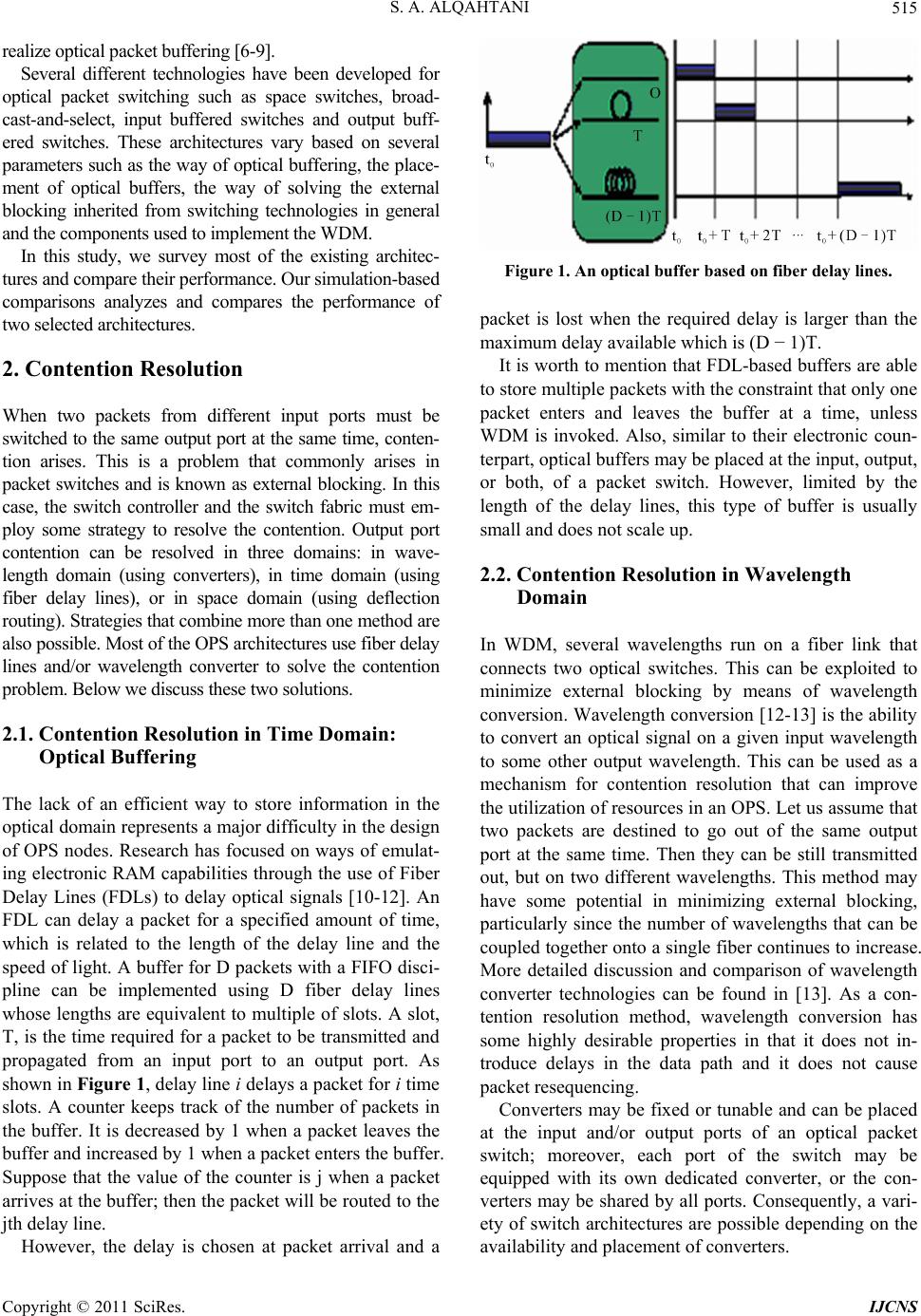 S. A. ALQAHTANI515 realize optical packet buffering [6-9]. Several different technologies have been developed for optical packet switching such as space switches, broad- cast-and-select, input buffered switches and output buff- ered switches. These architectures vary based on several parameters such as the way of optical buffering, the place- ment of optical buffers, the way of solving the external blocking inherited from switching technologies in general and the components used to implement the WDM. In this study, we survey most of the existing architec- tures and compare their performance. Our simulation-based comparisons analyzes and compares the performance of two selected architectures. 2. Contention Resolution When two packets from different input ports must be switched to the same output port at the same time, conten- tion arises. This is a problem that commonly arises in packet switches and is known as external blocking. In this case, the switch controller and the switch fabric must em- ploy some strategy to resolve the contention. Output port contention can be resolved in three domains: in wave- length domain (using converters), in time domain (using fiber delay lines), or in space domain (using deflection routing). Strategies that combine more than one method are also possible. Most of the OPS architectures use fiber delay lines and/or wavelength converter to solve the contention problem. Below we discuss these two solutions. 2.1. Contention Resolution in Time Domain: Optical Buffering The lack of an efficient way to store information in the optical domain represents a major difficulty in the design of OPS nodes. Research has focused on ways of emulat- ing electronic RAM capabilities through the use of Fiber Delay Lines (FDLs) to delay optical signals [10-12]. An FDL can delay a packet for a specified amount of time, which is related to the length of the delay line and the speed of light. A buffer for D packets with a FIFO disci- pline can be implemented using D fiber delay lines whose lengths are equivalent to multiple of slots. A slot, T, is the time required for a packet to be transmitted and propagated from an input port to an output port. As shown in Figure 1, delay line i delays a packet for i time slots. A counter keeps track of the number of packets in the buffer. It is decreased by 1 when a packet leaves the buffer and increased by 1 when a packet enters the buffer. Suppose that the value of the counter is j when a packet arrives at the buffer; then the packet will be routed to the jth delay line. However, the delay is chosen at packet arrival and a Figure 1. An optical buffer base d on fibe r de lay line s. packet is lost when the required delay is larger than the maximum delay available which is (D − 1)T. It is worth to mention that FDL-based buffers are able to store multiple packets with the constraint that only one packet enters and leaves the buffer at a time, unless WDM is invoked. Also, similar to their electronic coun- terpart, optical buffers may be placed at the input, output, or both, of a packet switch. However, limited by the length of the delay lines, this type of buffer is usually small and does not scale up. 2.2. Contention Resolution in Wavelength Domain In WDM, several wavelengths run on a fiber link that connects two optical switches. This can be exploited to minimize external blocking by means of wavelength conversion. Wavelength conversion [12-13] is the ability to convert an optical signal on a given input wavelength to some other output wavelength. This can be used as a mechanism for contention resolution that can improve the utilization of resources in an OPS. Let us assume that two packets are destined to go out of the same output port at the same time. Then they can be still transmitted out, but on two different wavelengths. This method may have some potential in minimizing external blocking, particularly since the number of wavelengths that can be coupled together onto a single fiber continues to increase. More detailed discussion and comparison of wavelength converter technologies can be found in [13]. As a con- tention resolution method, wavelength conversion has some highly desirable properties in that it does not in- troduce delays in the data path and it does not cause packet resequencing. Converters may be fixed or tunable and can be placed at the input and/or output ports of an optical packet switch; moreover, each port of the switch may be equipped with its own dedicated converter, or the con- verters may be shared by all ports. Consequently, a vari- ety of switch architectures are possible depending on the availability and placement of converters. Copyright © 2011 SciRes. IJCNS 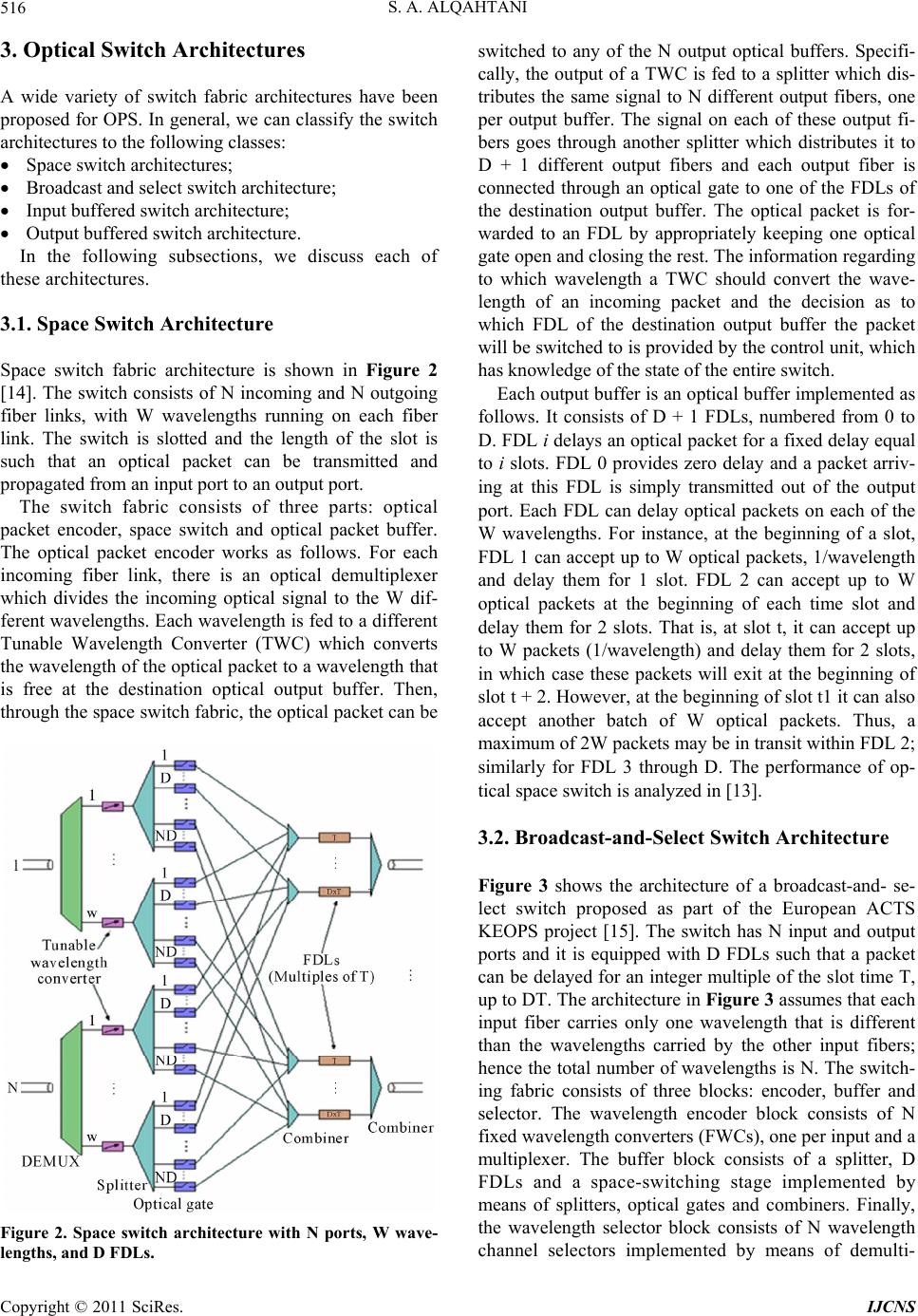 S. A. ALQAHTANI 516 3. Optical Switch Architectures A wide variety of switch fabric architectures have been proposed for OPS. In general, we can classify the switch architectures to the following classes: Space switch architectures; Broadcast and select switch architecture; Input buffered switch architecture; Output buffered switch architecture. In the following subsections, we discuss each of these architectures. 3.1. Space Switch Architecture Space switch fabric architecture is shown in Figure 2 [14]. The switch consists of N incoming and N outgoing fiber links, with W wavelengths running on each fiber link. The switch is slotted and the length of the slot is such that an optical packet can be transmitted and propagated from an input port to an output port. The switch fabric consists of three parts: optical packet encoder, space switch and optical packet buffer. The optical packet encoder works as follows. For each incoming fiber link, there is an optical demultiplexer which divides the incoming optical signal to the W dif- ferent wavelengths. Each wavelength is fed to a different Tunable Wavelength Converter (TWC) which converts the wavelength of the optical packet to a wavelength that is free at the destination optical output buffer. Then, through the space switch fabric, the optical packet can be Figure 2. Space switch architecture with N ports, W wave- lengths, and D FDLs. switched to any of the N output optical buffers. Specifi- cally, the output of a TWC is fed to a splitter which dis- tributes the same signal to N different output fibers, one per output buffer. The signal on each of these output fi- bers goes through another splitter which distributes it to D + 1 different output fibers and each output fiber is connected through an optical gate to one of the FDLs of the destination output buffer. The optical packet is for- warded to an FDL by appropriately keeping one optical gate open and closing the rest. The information regarding to which wavelength a TWC should convert the wave- length of an incoming packet and the decision as to which FDL of the destination output buffer the packet will be switched to is provided by the control unit, which has knowledge of the state of the entire switch. Each output buffer is an optical buffer implemented as follows. It consists of D + 1 FDLs, numbered from 0 to D. FDL i delays an optical packet for a fixed delay equal to i slots. FDL 0 provides zero delay and a packet arriv- ing at this FDL is simply transmitted out of the output port. Each FDL can delay optical packets on each of the W wavelengths. For instance, at the beginning of a slot, FDL 1 can accept up to W optical packets, 1/wavelength and delay them for 1 slot. FDL 2 can accept up to W optical packets at the beginning of each time slot and delay them for 2 slots. That is, at slot t, it can accept up to W packets (1/wavelength) and delay them for 2 slots, in which case these packets will exit at the beginning of slot t + 2. However, at the beginning of slot t1 it can also accept another batch of W optical packets. Thus, a maximum of 2W packets may be in transit within FDL 2; similarly for FDL 3 through D. The performance of op- tical space switch is analyzed in [13]. 3.2. Broadcast-and-Select Switch Architecture Figure 3 shows the architecture of a broadcast-and- se- lect switch proposed as part of the European ACTS KEOPS project [15]. The switch has N input and output ports and it is equipped with D FDLs such that a packet can be delayed for an integer multiple of the slot time T, up to DT. The architecture in Figure 3 assumes that each input fiber carries only one wavelength that is different than the wavelengths carried by the other input fibers; hence the total number of wavelengths is N. The switch- ing fabric consists of three blocks: encoder, buffer and selector. The wavelength encoder block consists of N fixed wavelength converters (FWCs), one per input and a multiplexer. The buffer block consists of a splitter, D FDLs and a space-switching stage implemented by means of splitters, optical gates and combiners. Finally, the wavelength selector block consists of N wavelength channel selectors implemented by means of demulti- Copyright © 2011 SciRes. IJCNS 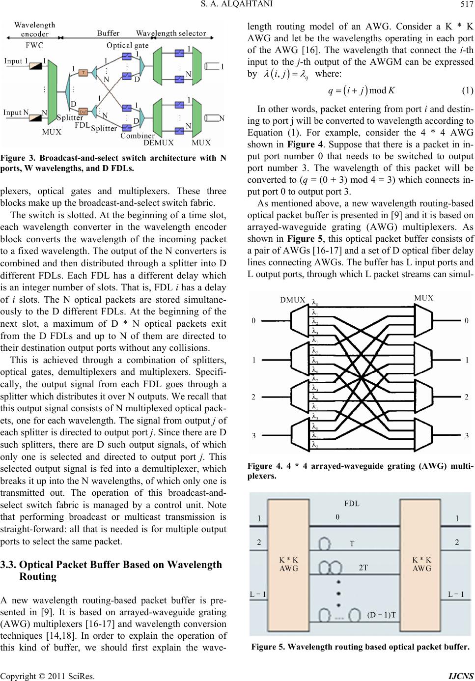 S. A. ALQAHTANI517 Figure 3. Broadcast-and-select switch architecture with N ports, W wavelengths, and D FDLs. plexers, optical gates and multiplexers. These three blocks make up the broadcast-and-select switch fabric. The switch is slotted. At the beginning of a time slot, each wavelength converter in the wavelength encoder block converts the wavelength of the incoming packet to a fixed wavelength. The output of the N converters is combined and then distributed through a splitter into D different FDLs. Each FDL has a different delay which is an integer number of slots. That is, FDL i has a delay of i slots. The N optical packets are stored simultane- ously to the D different FDLs. At the beginning of the next slot, a maximum of D * N optical packets exit from the D FDLs and up to N of them are directed to their destination output ports without any collisions. This is achieved through a combination of splitters, optical gates, demultiplexers and multiplexers. Specifi- cally, the output signal from each FDL goes through a splitter which distributes it over N outputs. We recall that this output signal consists of N multiplexed optical pack- ets, one for each wavelength. The signal from output j of each splitter is directed to output port j. Since there are D such splitters, there are D such output signals, of which only one is selected and directed to output port j. This selected output signal is fed into a demultiplexer, which breaks it up into the N wavelengths, of which only one is transmitted out. The operation of this broadcast-and- select switch fabric is managed by a control unit. Note that performing broadcast or multicast transmission is straight-forward: all that is needed is for multiple output ports to select the same packet. 3.3. Optical Packet Buffer Based on Wavelength Routing A new wavelength routing-based packet buffer is pre- sented in [9]. It is based on arrayed-waveguide grating (AWG) multiplexers [16-17] and wavelength conversion techniques [14,18]. In order to explain the operation of this kind of buffer, we should first explain the wave- length routing model of an AWG. Consider a K * K AWG and let be the wavelengths operating in each port of the AWG [16]. The wavelength that connect the i-th input to the j-th output of the AWGM can be expressed by ,q ij where: modqij K (1) In other words, packet entering from port i and destin- ing to port j will be converted to wavelength according to Equation (1). For example, consider the 4 * 4 AWG shown in Figure 4. Suppose that there is a packet in in- put port number 0 that needs to be switched to output port number 3. The wavelength of this packet will be converted to (q = (0 + 3) mod 4 = 3) which connects in- put port 0 to output port 3. As mentioned above, a new wavelength routing-based optical packet buffer is presented in [9] and it is based on arrayed-waveguide grating (AWG) multiplexers. As shown in Figure 5, this optical packet buffer consists of a pair of AWGs [16-17] and a set of D optical fiber delay lines connecting AWGs. The buffer has L input ports and L output ports, through which L packet streams can simul- Figure 4. 4 * 4 arrayed-waveguide grating (AWG) multi- plexers. Figure 5. Wavelength routing based optical packet buffer. Copyright © 2011 SciRes. IJCNS 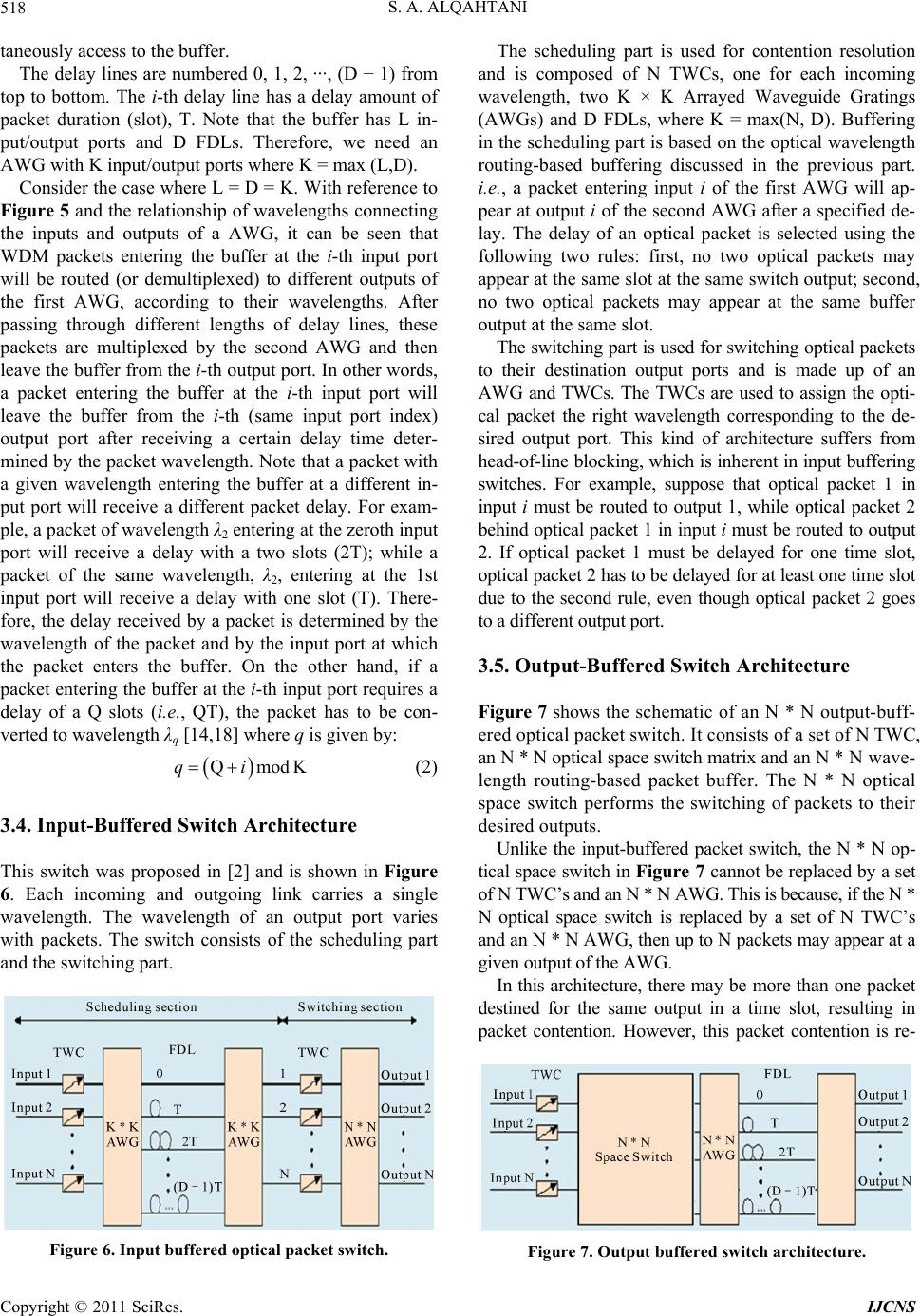 S. A. ALQAHTANI 518 taneously access to the buffer. The delay lines are numbered 0, 1, 2, ···, (D − 1) from top to bottom. The i-th delay line has a delay amount of packet duration (slot), T. Note that the buffer has L in- put/output ports and D FDLs. Therefore, we need an AWG with K input/output ports where K = max (L,D). Consider the case where L = D = K. With reference to Figure 5 and the relationship of wavelengths connecting the inputs and outputs of a AWG, it can be seen that WDM packets entering the buffer at the i-th input port will be routed (or demultiplexed) to different outputs of the first AWG, according to their wavelengths. After passing through different lengths of delay lines, these packets are multiplexed by the second AWG and then leave the buffer from the i-th output port. In other words, a packet entering the buffer at the i-th input port will leave the buffer from the i-th (same input port index) output port after receiving a certain delay time deter- mined by the packet wavelength. Note that a packet with a given wavelength entering the buffer at a different in- put port will receive a different packet delay. For exam- ple, a packet of wavelength λ2 entering at the zeroth input port will receive a delay with a two slots (2T); while a packet of the same wavelength, λ2, entering at the 1st input port will receive a delay with one slot (T). There- fore, the delay received by a packet is determined by the wavelength of the packet and by the input port at which the packet enters the buffer. On the other hand, if a packet entering the buffer at the i-th input port requires a delay of a Q slots (i.e., QT), the packet has to be con- verted to wavelength λq [14,18] where q is given by: QmodKqi (2) 3.4. Input-Buffered Switch Architecture This switch was proposed in [2] and is shown in Figure 6. Each incoming and outgoing link carries a single wavelength. The wavelength of an output port varies with packets. The switch consists of the scheduling part and the switching part. Figure 6. Input buffered optical packet switch. The scheduling part is used for contention resolution and is composed of N TWCs, one for each incoming wavelength, two K × K Arrayed Waveguide Gratings (AWGs) and D FDLs, where K = max(N, D). Buffering in the scheduling part is based on the optical wavelength routing-based buffering discussed in the previous part. i.e., a packet entering input i of the first AWG will ap- pear at output i of the second AWG after a specified de- lay. The delay of an optical packet is selected using the following two rules: first, no two optical packets may appear at the same slot at the same switch output; second, no two optical packets may appear at the same buffer output at the same slot. The switching part is used for switching optical packets to their destination output ports and is made up of an AWG and TWCs. The TWCs are used to assign the opti- cal packet the right wavelength corresponding to the de- sired output port. This kind of architecture suffers from head-of-line blocking, which is inherent in input buffering switches. For example, suppose that optical packet 1 in input i must be routed to output 1, while optical packet 2 behind optical packet 1 in input i must be routed to output 2. If optical packet 1 must be delayed for one time slot, optical packet 2 has to be delayed for at least one time slot due to the second rule, even though optical packet 2 goes to a different output port. 3.5. Output-Buffered Switch Architecture Figure 7 shows the schematic of an N * N output-buff- ered optical packet switch. It consists of a set of N TWC, an N * N optical space switch matrix and an N * N wave- length routing-based packet buffer. The N * N optical space switch performs the switching of packets to their desired outputs. Unlike the input-buffered packet switch, the N * N op- tical space switch in Figure 7 cannot be replaced by a set of N TWC’s and an N * N AWG. This is because, if the N * N optical space switch is replaced by a set of N TWC’s and an N * N AWG, then up to N packets may appear at a given output of the AWG. In this architecture, there may be more than one packet destined for the same output in a time slot, resulting in packet contention. However, this packet contention is re- Figure 7. Output buffered switch architecture. Copyright © 2011 SciRes. IJCNS 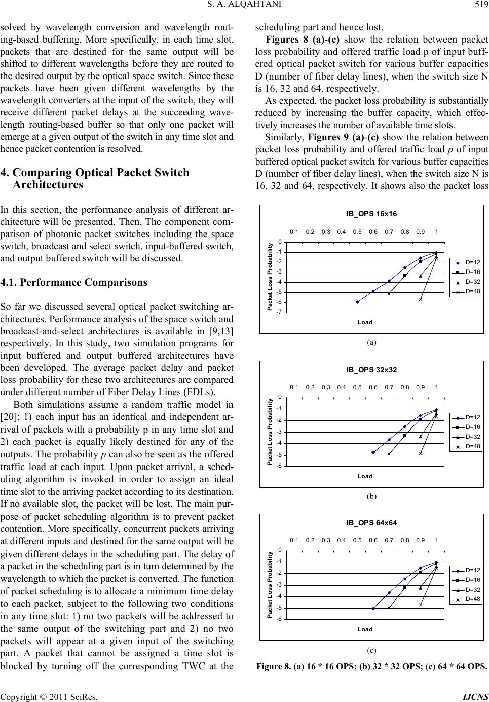 S. A. ALQAHTANI519 solved by wavelength conversion and wavelength rout- ing-based buffering. More specifically, in each time slot, packets that are destined for the same output will be shifted to different wavelengths before they are routed to the desired output by the optical space switch. Since these packets have been given different wavelengths by the wavelength converters at the input of the switch, they will receive different packet delays at the succeeding wave- length routing-based buffer so that only one packet will emerge at a given output of the switch in any time slot and hence packet contention is resolved. 4. Comparing Optical Packet Switch Architectures In this section, the performance analysis of different ar- chitecture will be presented. Then, The component com- parison of photonic packet switches including the space switch, broadcast and select switch, input-buffered switch, and output buffered switch will be discussed. 4.1. Performance Comparisons So far we discussed several optical packet switching ar- chitectures. Performance analysis of the space switch and broadcast-and-select architectures is available in [9,13] respectively. In this study, two simulation programs for input buffered and output buffered architectures have been developed. The average packet delay and packet loss probability for these two architectures are compared under different number of Fiber Delay Lines (FDLs). Both simulations assume a random traffic model in [20]: 1) each input has an identical and independent ar- rival of packets with a probability p in any time slot and 2) each packet is equally likely destined for any of the outputs. The probability p can also be seen as the offered traffic load at each input. Upon packet arrival, a sched- uling algorithm is invoked in order to assign an ideal time slot to the arriving packet according to its destination. If no available slot, the packet will be lost. The main pur- pose of packet scheduling algorithm is to prevent packet contention. More specifically, concurrent packets arriving at different inputs and destined for the same output will be given different delays in the scheduling part. The delay of a packet in the scheduling part is in turn determined by the wavelength to which the packet is converted. The function of packet scheduling is to allocate a minimum time delay to each packet, subject to the following two conditions in any time slot: 1) no two packets will be addressed to the same output of the switching part and 2) no two packets will appear at a given input of the switching part. A packet that cannot be assigned a time slot is blocked by turning off the corresponding TWC at the scheduling part and hence lost. Figures 8 (a)-(c) show the relation between packet loss probability and offered traffic load p of input buff- ered optical packet switch for various buffer capacities D (number of fiber delay lines), when the switch size N is 16, 32 and 64, respectively. As expected, the packet loss probability is substantially reduced by increasing the buffer capacity, which effec- tively increases the number of available time slots. Similarly, Figures 9 (a)-(c) show the relation between packet loss probability and offered traffic load p of input buffered optical packet switch for various buffer capacities D (number of fiber delay lines), when the switch size N is 16, 32 and 64, respectively. It shows also the packet loss IB_O PS 16x16 -7 -6 -5 -4 -3 -2 -1 0 0.1 0.2 0.30.4 0.5 0.6 0.70.80.91 Loa d P acket L oss Pr o bab ilit y D= 1 2 D= 1 6 D= 3 2 D= 4 8 (a) IB_O PS 32x32 -6 -5 -4 -3 -2 -1 0 0.1 0.20.30.4 0.50.60.7 0.80.91 Loa d Packet Loss Probability D= 1 2 D= 1 6 D= 3 2 D= 4 8 (b) IB_O PS 64x64 -6 -5 -4 -3 -2 -1 0 0.1 0.20.30.4 0.50.60.70.80.91 Loa d Packet Loss Probability D= 1 2 D= 1 6 D= 3 2 D= 4 8 (c) Figure 8. (a) 16 * 16 OPS; (b) 32 * 32 OPS; (c) 64 * 64 OPS. Copyright © 2011 SciRes. IJCNS 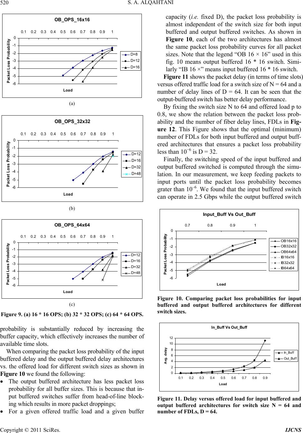 S. A. ALQAHTANI 520 OB_OPS_16x16 -6 -5 -4 -3 -2 -1 0 0.1 0.2 0.30.4 0.5 0.60.7 0.80.91 Load Packet Loss Probability D=8 D=12 D=16 (a) OB_OPS_32x32 -6 -5 -4 -3 -2 -1 0 0.1 0.2 0.30.4 0.5 0.6 0.7 0.80.91 Load P acket Lo ss P rob ab ility D=12 D=16 D=32 D=48 (b) OB_OPS_64x64 -6 -5 -4 -3 -2 -1 0 0.1 0.2 0.3 0.4 0.5 0.6 0.7 0.80.91 Load P acket Loss Probab il it y D= 12 D= 16 D= 32 D= 48 (c) Figure 9. (a) 16 * 16 OPS; (b) 32 * 32 OPS; (c) 64 * 64 OPS. probability is substantially reduced by increasing the buffer capacity, which effectively increases the number of available time slots. When comparing the packet loss probability of the input buffered delay and the output buffered delay architectures vs. the offered load for different switch sizes as shown in Figure 10 we found the following: The output buffered architecture has less packet loss probability for all buffer sizes. This is because that in- put buffered switches suffer from head-of-line block- ing which results in more packet droppings; For a given offered traffic load and a given buffer capacity (i.e. fixed D), the packet loss probability is almost independent of the switch size for both input buffered and output buffered switches. As shown in Figure 10, each of the two architectures has almost the same packet loss probability curves for all packet sizes. Note that the legend “OB 16 × 16” used in this fig. 10 means output buffered 16 * 16 switch. Simi- larly “IB 16 ×” means input buffered 16 * 16 switch. Figure 11 shows the packet delay (in terms of time slots) versus offered traffic load for a switch size of N = 64 and a number of delay lines of D = 64. It can be seen that the output-buffered switch has better delay performance. By fixing the switch size N to 64 and offered load p to 0.8, we show the relation between the packet loss prob- ability and the number of fiber delay lines, FDLs in Fig- ure 12. This Figure shows that the optimal (minimum) number of FDLs for both input buffered and output buff- ered architectures that ensures a packet loss probability less than 10−6 is D = 32. Finally, the switching speed of the input buffered and output buffered switched is computed through the simu- lation. In our measurement, we keep feeding packets to input ports until the packet loss probability becomes grater than 10–6. We found that the input buffered switch can operate in 2.5 Gbps while the output buffered switch Input_Buf f Vs Out _Buf f -6 -5 -4 -3 -2 -1 0 0.7 0.8 0.91 Load Packet Loss Probability OB16x16 OB32x32 OB64x64 IB16x16 IB32x32 IB64x64 Figure 10. Comparing packet loss probabilities for input buffered and output buffered architectures for different switch sizes. I n _Bu f f V s Ou t_ Buf f 0 2 4 6 8 10 12 0.1 0.20.3 0.4 0.5 0.6 0.70.8 0.9 Load Avg. delay In_Buff Out_Buff Figure 11. Delay versus offered load for input buffered and output buffered architectures for switch size N = 64 and number of FDLs, D = 64. Copyright © 2011 SciRes. IJCNS 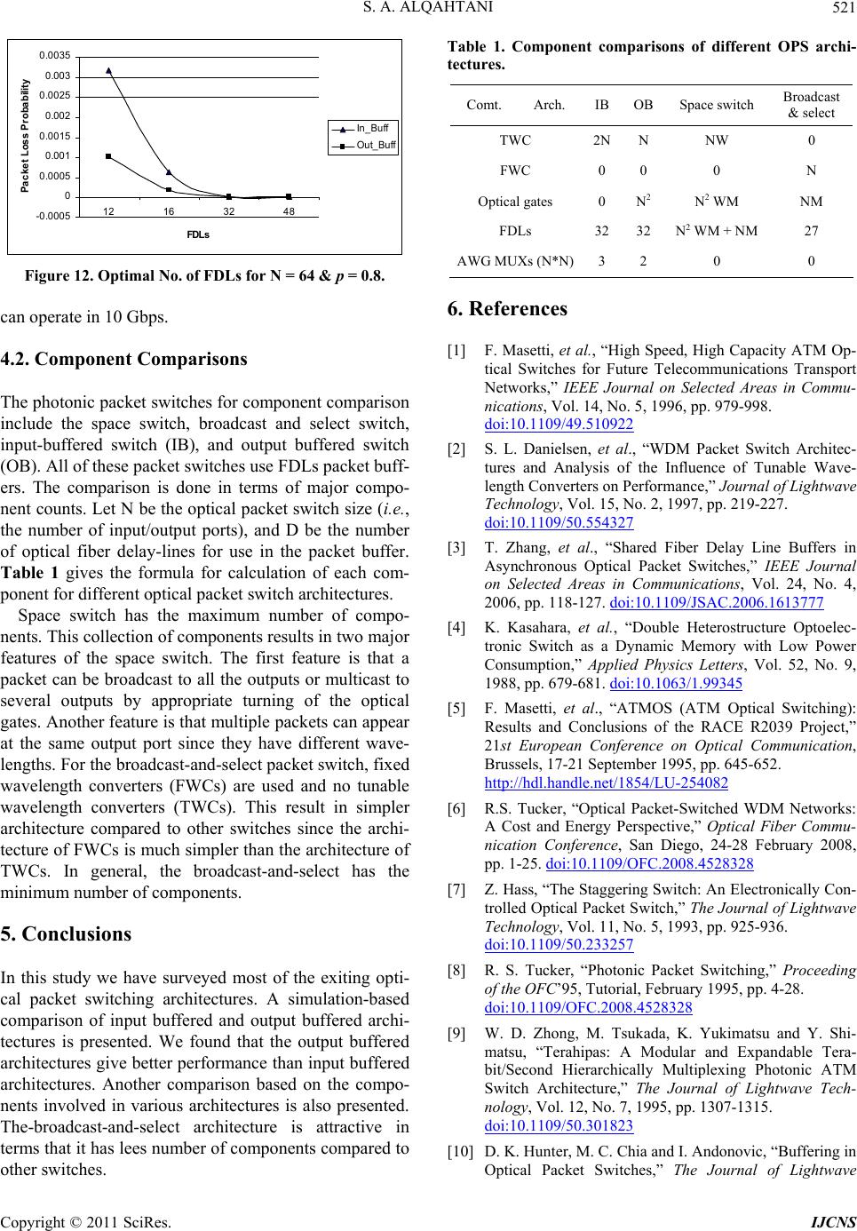 S. A. ALQAHTANI521 -0.0005 0 0.0005 0.001 0.0015 0.002 0.0025 0.003 0.0035 12 16 32 48 FD Ls Packe t Loss Proba bility In_Buff Ou t_Buff Figure 12. Optimal No. of FDLs for N = 64 & p = 0.8. can operate in 10 Gbps. 4.2. Component Comparisons The photonic packet switches for component comparison include the space switch, broadcast and select switch, input-buffered switch (IB), and output buffered switch (OB). All of these packet switches use FDLs packet buff- ers. The comparison is done in terms of major compo- nent counts. Let N be the optical packet switch size (i.e., the number of input/output ports), and D be the number of optical fiber delay-lines for use in the packet buffer. Table 1 gives the formula for calculation of each com- ponent for different optical packet switch architectures. Space switch has the maximum number of compo- nents. This collection of components results in two major features of the space switch. The first feature is that a packet can be broadcast to all the outputs or multicast to several outputs by appropriate turning of the optical gates. Another feature is that multiple packets can appear at the same output port since they have different wave- lengths. For the broadcast-and-select packet switch, fixed wavelength converters (FWCs) are used and no tunable wavelength converters (TWCs). This result in simpler architecture compared to other switches since the archi- tecture of FWCs is much simpler than the architecture of TWCs. In general, the broadcast-and-select has the minimum number of components. 5. Conclusions In this study we have surveyed most of the exiting opti- cal packet switching architectures. A simulation-based comparison of input buffered and output buffered archi- tectures is presented. We found that the output buffered architectures give better performance than input buffered architectures. Another comparison based on the compo- nents involved in various architectures is also presented. The-broadcast-and-select architecture is attractive in terms that it has lees number of components compared to other switches. Table 1. Component comparisons of different OPS archi- tectures. Comt. Arch. IB OB Space switch Broadcast & select TWC 2NN NW 0 FWC 0 0 0 N Optical gates 0 N2 N 2 WM NM FDLs 32 32 N2 WM + NM 27 AWG MUXs (N*N)3 2 0 0 6. References [1] F. Masetti, et al., “High Speed, High Capacity ATM Op- tical Switches for Future Telecommunications Transport Networks,” IEEE Journal on Selected Areas in Commu- nications, Vol. 14, No. 5, 1996, pp. 979-998. doi:10.1109/49.510922 [2] S. L. Danielsen, et al., “WDM Packet Switch Architec- tures and Analysis of the Influence of Tunable Wave- length Converters on Performance,” Journal of Lightwave Technology, Vol. 15, No. 2, 1997, pp. 219-227. doi:10.1109/50.554327 [3] T. Zhang, et al., “Shared Fiber Delay Line Buffers in Asynchronous Optical Packet Switches,” IEEE Journal on Selected Areas in Communications, Vol. 24, No. 4, 2006, pp. 118-127. doi:10.1109/JSAC.2006.1613777 [4] K. Kasahara, et al., “Double Heterostructure Optoelec- tronic Switch as a Dynamic Memory with Low Power Consumption,” Applied Physics Letters, Vol. 52, No. 9, 1988, pp. 679-681. doi:10.1063/1.99345 [5] F. Masetti, et al., “ATMOS (ATM Optical Switching): Results and Conclusions of the RACE R2039 Project,” 21st European Conference on Optical Communication, Brussels, 17-21 September 1995, pp. 645-652. http://hdl.handle.net/1854/LU-254082 [6] R.S. Tucker, “Optical Packet-Switched WDM Networks: A Cost and Energy Perspective,” Optical Fiber Commu- nication Conference, San Diego, 24-28 February 2008, pp. 1-25. doi:10.1109/OFC.2008.4528328 [7] Z. Hass, “The Staggering Switch: An Electronically Con- trolled Optical Packet Switch,” The Journal of Lightwave Technology, Vol. 11, No. 5, 1993, pp. 925-936. doi:10.1109/50.233257 [8] R. S. Tucker, “Photonic Packet Switching,” Proceeding of the OFC’95, Tutorial, February 1995, pp. 4-28. doi:10.1109/OFC.2008.4528328 [9] W. D. Zhong, M. Tsukada, K. Yukimatsu and Y. Shi- matsu, “Terahipas: A Modular and Expandable Tera- bit/Second Hierarchically Multiplexing Photonic ATM Switch Architecture,” The Journal of Lightwave Tech- nology, Vol. 12, No. 7, 1995, pp. 1307-1315. doi:10.1109/50.301823 [10] D. K. Hunter, M. C. Chia and I. Andonovic, “Buffering in Optical Packet Switches,” The Journal of Lightwave Copyright © 2011 SciRes. IJCNS  S. A. ALQAHTANI Copyright © 2011 SciRes. IJCNS 522 Technology, Vol. 16, No. 12, 1998, pp. 2081-2094. doi:10.1109/50.736577 [11] D. K. Hunter, W. D. Cornwell, T. H. Gilfedder, A. Fren- zen and I. Andonovic, “SLOB: A Switch with Large Op- tical Buffers for Packet Switching,” The Journal of Lightwave Technology, Vol. 16, No. 10, 1998, pp. 1725- 1736. doi:10.1109/50.721059 [12] B. Ramamurthy and B. Mukherjee, “Wavelength Con- version in WDM Networking,” IEEE Journal on Selected Areas in Communications, Vol. 16, No. 7, 1998, pp. 1061-1073. doi:10.1109/49.725178 [13] J. M. H. Elmirghani, and H. T. Mouftah, “All-Optical Wavelength Conversion: Technologies and Applications on DWDM Networks,” IEEE Communications Magazine, Vol. 38, No. 3, 2000, pp. 86-92. doi:10.1109/35.825645 [14] B. S. Glance, et al., “New Advances on Optical Compo- nents Needed for FDM Optical Networks,” The Journal of Lightwave Technology, Vol. 11, No. 5-6, 1993, pp. 882-889. doi:10.1109/50.233252 [15] C. Guillemot, et al., “Transparent Optical Packet Switch- ing: The European ACTS KEOPS Project Approach,” The Journal of Lightwave Technology, Vol. 16, No. 12, 1998, pp. 2117-2134. doi:10.1109/LEOS.1999.811768 [16] H. Takahashi, et al., “Arrayed-Waveguide Grating for Wavelength Division Multi/Demultiplexer with Nano- meter Resolution,” Electronics Letters, Vol. 26, No. 2, 1998, pp. 87-88. doi:10.1049/el:19900058 [17] C. Dragone, “An N * N Optical Multiplexer Using a Pla- nar Arrangement of Two Star Couplers,” IEEE Photonics Technology Letters, Vol. 3, No. 9, 1991, pp. 896-899. doi:10.1109/68.84502 [18] T. Durhuus, et al., “All-Optical Wavelength Conversion by Semiconductor Optical Amplifiers,” The Journal of Lightwave Technology, Vol. 14, No. 6, 1996, pp. 942-954. doi:10.1109/50.511594 [19] K. Sasayama, K. Habara, W. D. Zhong and K. Yukimatsu, “Photonic ATM Switch Using Frequency-Routing-Type Time-Division Interconnection Network,” Electronics Letters, Vol. 29, No. 20, 1993, pp. 1778-1779. doi:10.1049/el:19931184 [20] M. G. Hluchyj and M. J. Karol, “Queueing in High-Per- Formance Packet Switching,” IEEE Journal on Selected Areas in Communications, Vol. 6, No. 9, 1988, pp. 1587-1597. doi:10.1109/49.12886
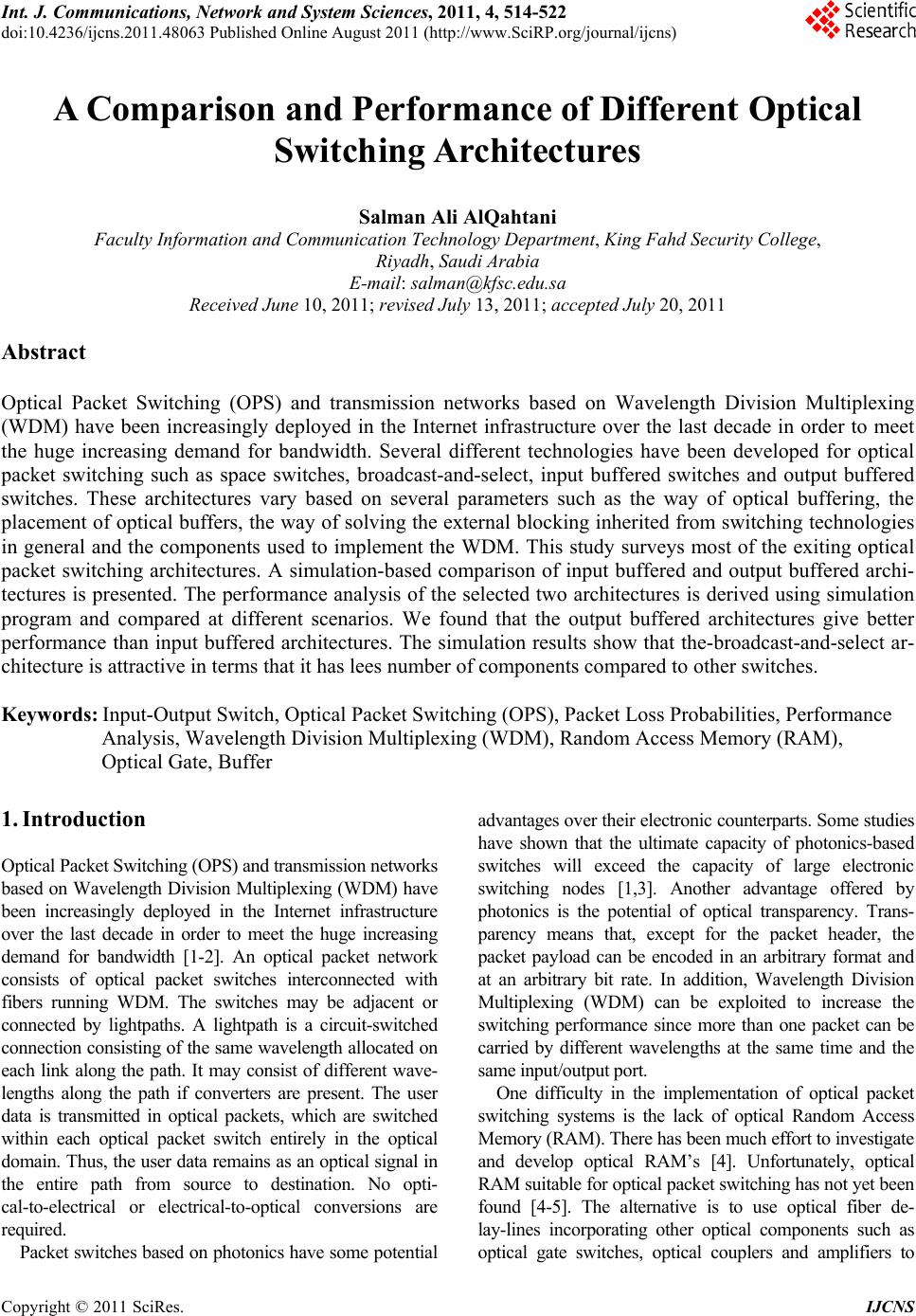
|