R. B. XU ET AL.
247
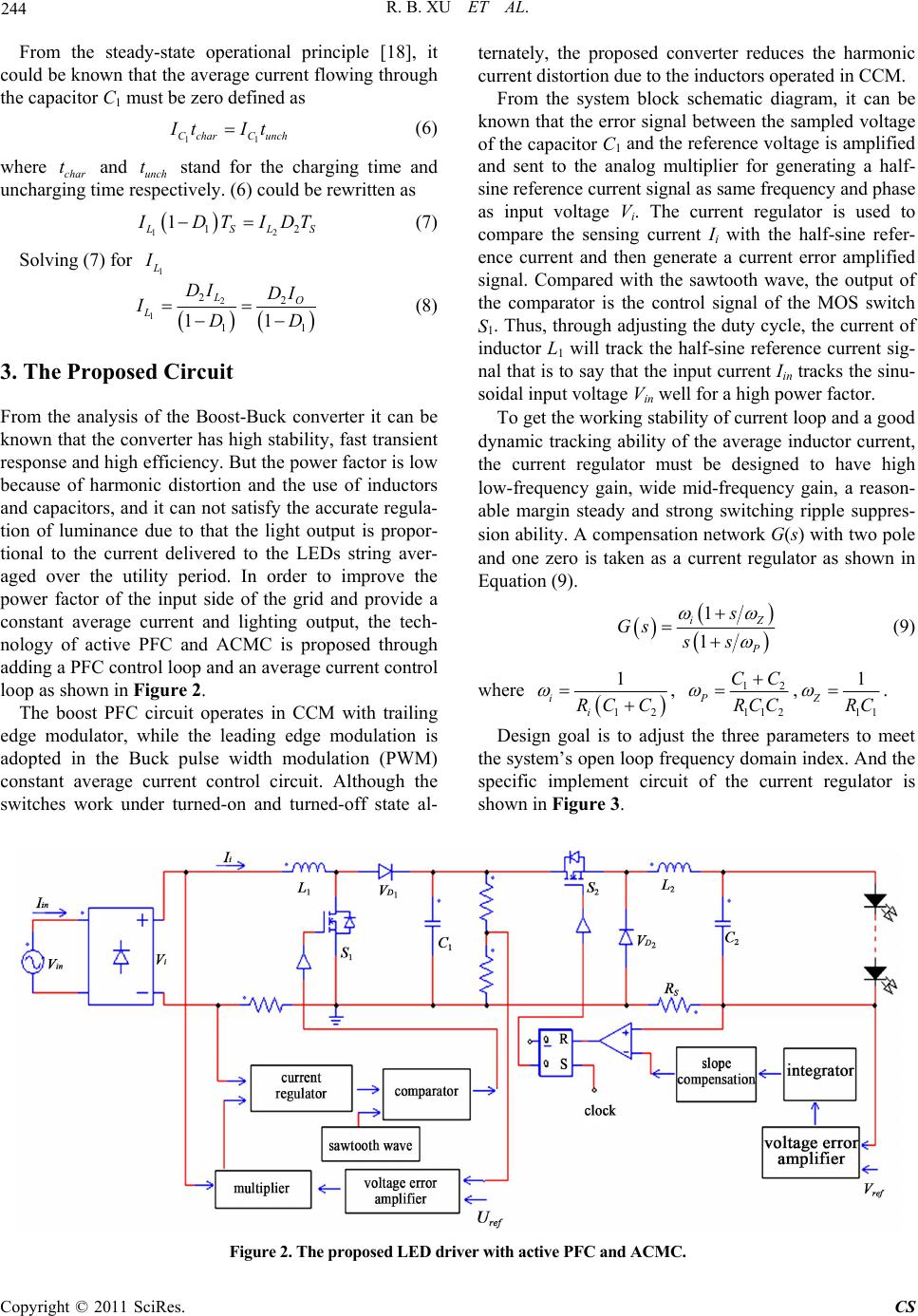
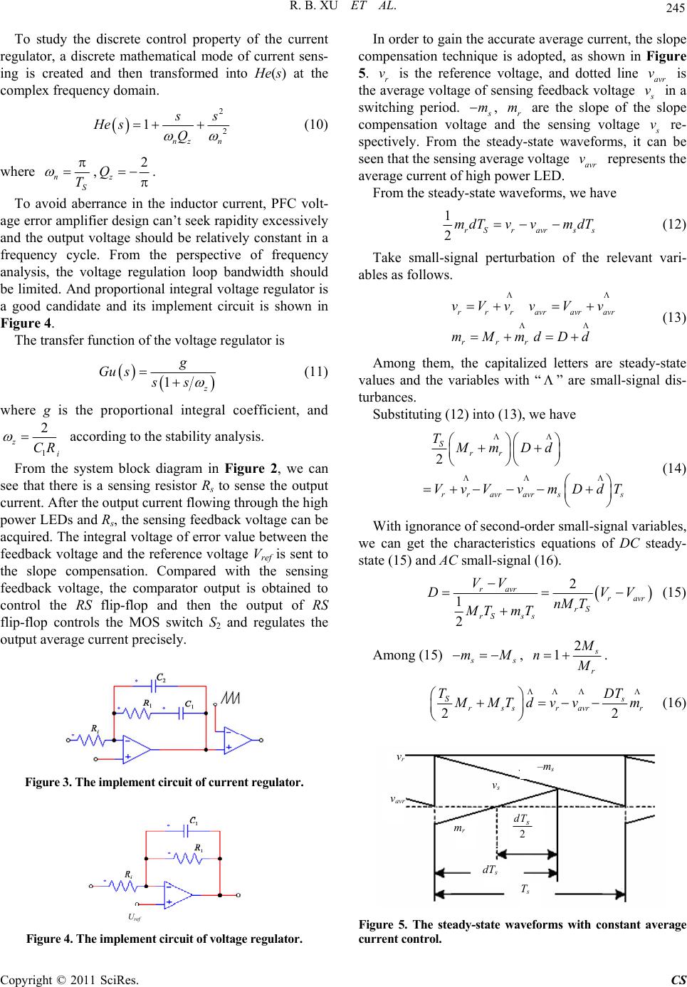
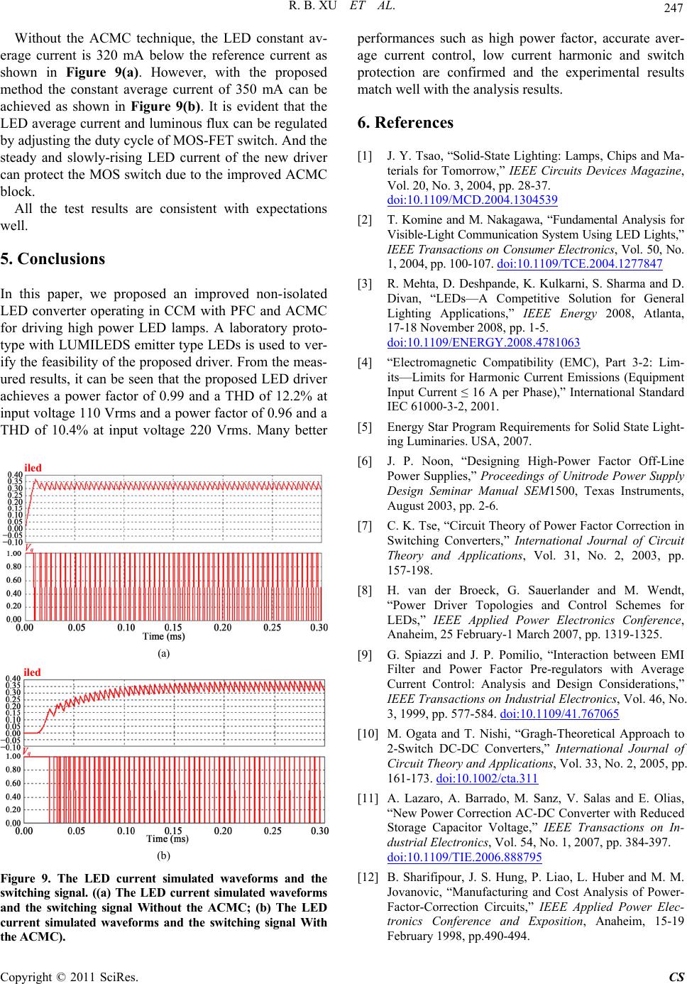
Without the ACMC technique, the LED constant av-
erage current is 320 mA below the reference current as
shown in Figure 9(a). However, with the proposed
method the constant average current of 350 mA can be
achieved as shown in Figure 9(b). It is evident that the
LED average current and luminous flux can be regulated
by adjusting the duty cycle of MOS-FET switch. And the
steady and slowly-rising LED current of the new driver
can protect the MOS switch due to the improved ACMC
block.
All the test results are consistent with expectations
well.
5. Conclusions
In this paper, we proposed an improved non-isolated
LED converter operating in CCM with PFC and ACMC
for driving high power LED lamps. A laboratory proto-
type with LUMILEDS emitter type LEDs is used to ver-
ify the feasibility of the proposed driver. From the meas-
ured results, it can be seen that the proposed LED driver
achieves a power factor of 0.99 and a THD of 12.2% at
input voltage 110 Vrms and a power factor of 0.96 and a
THD of 10.4% at input voltage 220 Vrms. Many better
(a)
(b)
Figure 9. The LED current simulated waveforms and the
switching signal. ((a) The LED current simulated waveforms
and the switching signal Without the ACMC; (b) The LED
current simulated waveforms and the switching signal With
the ACMC).
performances such as high power factor, accurate aver-
age current control, low current harmonic and switch
protection are confirmed and the experimental results
match well with the analysis results.
6. References
[1] J. Y. Tsao, “Solid-State Lighting: Lamps, Chips and Ma-
terials for Tomorrow,” IEEE Circuits Devices Magazine,
Vol. 20, No. 3, 2004, pp. 28-37.
doi:10.1109/MCD.2004.1304539
[2] T. Komine and M. Nakagawa, “Fundamental Analysis for
Visible-Light Communication System Using LED Lights,”
IEEE Transactions on Consumer Electronics, Vol. 50, No.
1, 2004, pp. 100-107. doi:10.1109/TCE.2004.1277847
[3] R. Mehta, D. Deshpande, K. Kulkarni, S. Sharma and D.
Divan, “LEDs—A Competitive Solution for General
Lighting Applications,” IEEE Energy 2008, Atlanta,
17-18 November 2008, pp. 1-5.
doi:10.1109/ENERGY.2008.4781063
[4] “Electromagnetic Compatibility (EMC), Part 3-2: Lim-
its—Limits for Harmonic Current Emissions (Equipment
Input Current ≤ 16 A per Phase),” International Standard
IEC 61000-3-2, 2001.
[5] Energy Star Program Requirements for Solid State Light-
ing Luminaries. USA, 2007.
[6] J. P. Noon, “Designing High-Power Factor Off-Line
Power Supplies,” Proceedings of Unitrode Power Supply
Design Seminar Manual SEM1500, Texas Instruments,
August 2003, pp. 2-6.
iled
[7] C. K. Tse, “Circuit Theory of Power Factor Correction in
Switching Converters,” International Journal of Circuit
Theory and Applications, Vol. 31, No. 2, 2003, pp.
157-198.
[8] H. van der Broeck, G. Sauerlander and M. Wendt,
“Power Driver Topologies and Control Schemes for
LEDs,” IEEE Applied Power Electronics Conference,
Anaheim, 25 February-1 March 2007, pp. 1319-1325.
[9] G. Spiazzi and J. P. Pomilio, “Interaction between EMI
Filter and Power Factor Pre-regulators with Average
Current Control: Analysis and Design Considerations,”
IEEE Transactions on Industrial Electronics, Vol. 46, No.
3, 1999, pp. 577-584. doi:10.1109/41.767065
iled
[10] M. Ogata and T. Nishi, “Gragh-Theoretical Approach to
2-Switch DC-DC Converters,” International Journal of
Circuit Theory and Applications, Vol. 33, No. 2, 2005, pp.
161-173. doi:10.1002/cta.311
[11] A. Lazaro, A. Barrado, M. Sanz, V. Salas and E. Olias,
“New Power Correction AC-DC Converter with Reduced
Storage Capacitor Voltage,” IEEE Transactions on In-
dustrial Electronics, Vol. 54, No. 1, 2007, pp. 384-397.
doi:10.1109/TIE.2006.888795
[12] B. Sharifipour, J. S. Hung, P. Liao, L. Huber and M. M.
Jovanovic, “Manufacturing and Cost Analysis of Power-
Factor-Correction Circuits,” IEEE Applied Power Elec-
tronics Conference and Exposition, Anaheim, 15-19
February 1998, pp.490-494.
Copyright © 2011 SciRes. CS