Wireless Engineering and Technology
Vol.4 No.4(2013), Article ID:38680,10 pages DOI:10.4236/wet.2013.44028
Resource Optimisation for 3rd Generation Partnership Project (3GPP) Long Term Evolution OFDMA Downlink Interface Air
![]()
1MTN, Nigeria; 2Federal University of Technology Akure, Akure, Nigeria.
Email: ayoakinniranye@yahoo.com, samlove98ng@yahoo.com
Copyright © 2013 Ayoola Akinloye Akinniranye, Samson Adenle Oyetunji. This is an open access article distributed under the Creative Commons Attribution License, which permits unrestricted use, distribution, and reproduction in any medium, provided the original work is properly cited.
Received July 16th, 2013; revised August 27th, 2013; accepted September 10th, 2013
Keywords: Communication Channels; Wireless Mobile Communications; Noise; OFDMA
ABSTRACT
This Paper describes the system model of the developed optimisation scheme which is implemented using a simulation package known as MATLAB. The 3rd Generation Partnership Project (3GPP) Long Term Evolution standard for the downlink air interface, Orthogonal Frequency Division Multiple Access (OFDMA) was adopted. Frequency Selective Rayleigh fading channel is considered as a model for real life scenario of the LTE Evaluation, operating in 5 MHz downlink bandwidth of OFDMA parameters as proposed in the standard. Simulation results show that, the inherent characteristics of a communication channel can be exploited and combined with the robustness of OFDMA to optimally allocate the radio resources. The optimal channel assignment of the dynamic allocation scheme exploited in this work meets the set target of high data rate and spectral efficiency.
1. Introduction
Wireless communication is enjoying a fast growth period in history which is coupled with technology improvements that permit its widespread deployment. That is the cellular concept developed by Bell Laboratories [1]. Mobile communication offers a full duplex communication using a radio to connect portable device to a dedicated Base station, which is then connected to a switching network. The first generation of mobile communication, known as Advanced Mobile Phone System (AMPS), was deployed in 1983 [1]. The second generation (2G) of mobile communication is known as Global System for Mobile communication (GSM) which was deployed in the 1990s [1] with 9.6 kbps data rate. The International Telecommunications Union (ITU) developed a plan in 1995 [2].
Called International Mobile Telecommunication 2000 (IMT-2000) implements a global frequency band [1,3] for the future mobile development. The third Generation system (3G) standard deployed in 21st century improves the data handling capacity with data rate of 64 kbps to 2 Mbps. A collaborative group of standards organisation and telecommunication companies called Third Generation Partnership Project (3GPP) was formed for enhanced versions to the 3G standard. Evolved from 3GPP standards in 2004 [4], it is the Release 8 version, which is known as Long Term Evolution (LTE) which targets to support high data rate of 100 Mbps for the downlink and 50 Mbps for the uplink with low delay, higher data rate, flexible bandwidth and optimised radio access and cell edge performance [5]. For the Downlink, Orthogonal Frequency Division Multiple Access (OFDMA) is considered for transmitting from Base Station (BS) otherwise known as Node B to the mobile user which is known as User Equipment (UE) while Single Carrier Frequency Division Multiple Access (SC-FDMA) is for the Uplink. This work focuses on the Downlink access. In a rapidly growing environment, overall system performance will depend on the ability to provide power and spectrum efficiency, adaptive to wireless fading and channel characteristics and support to changing UE traffics.
2. Wireless Channel Characteristics
Wireless channel is an unguided channel and signals not only contain the direct Line of Sight LOS waves; but also a number of signals as a result of diffraction, reflection and scattering as shown in Figure 1. This propagation

Figure 1. Multipath signal reception of a moving receiver.
type is termed Multipath [2] degrades the performance of the channel. Similarly, the channel may introduce Doppler Effect when the transmitter or receiver moves.
2.1. Additive White Gaussian Noise Channel
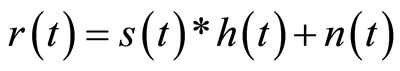
Additive White Gaussian Noise (AWGN) channel is a good model for the physical reality of channel, as long as the thermal noise at the receiver is the only source of disturbance [6]. The impairment this channel caused to signal is the addition of Gaussian distributed noise. Mathematically, it can be illustrated as:
 (1)
(1)
where  is the received signal,
  is the transmitted signal and
  is the noise.
2.2. Multi Path Fading Channels
An alternative class of channel used to model communication system is fading channels because mobile reception is harshly affected by multipath propagation which results in Fading or Inter-symbol.
Interference (ISI). This can be mathematically expressed as:
 (2)
(2)
Time disperse signal are often affected by the delay spread. If the delay spread is less than the symbol period Ts or the signal bandwidth BW is less than the Coherence bandwidth, the signal channel is categorised as Flat fading which preserves of the spectral characteristics of the signal at the receiver [2]. In contrast, if signal bandwidth is more than the coherence bandwidth or delay spread is more than the symbol period, then the channel is categorised as Frequency Selective fading and leads to ISI which degrades the channel.
2.3. Channel Models
Andrea stated in [3] that deterministic channel models are rarely available. But to evaluate the performance of signals properly in fading channels, this work considered Flat and Frequency Selective fading channel and few of the models.
A. Rayleigh and Rician Fading Model
Rayleigh distribution model is often used for fading signal with infinite or large number of arrival paths at the same time whose gain are statistically independent and no dominant path [2]. The phase component of the channel gain is Gaussian distributed and equation 3 is its probability density function (PDF) as stated by Rappaport [1]:
 (3)
(3)
where, σ is the RMS value of received signal before detection.
And according to [4], the average channel power is given by:
 (4)
(4)
Similar to the distribution properties of Rayleigh is the Rician Distribution model except for the presence of a dominant path with numerous weak paths. Inclusive in its pdf (equation 5 [2]) is the peak amplitude A of dominant signal and zero-order Bessel function I, of the first kind
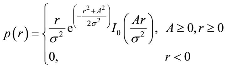 (5)
(5)
B. Clarkes’ Fading Model
The model assumes all multipath signals arrive at the same time in horizontal direction and when the mobile user moves, each path will experience a different Doppler shift. Hence, a uniform probability density function (PDF) of the rays is assumed and a Doppler effect is introduced due to respective movement of the receiver [7].
C. ITU Model
International Telecommunications Union published some generic test models that are commonly used in the communication industry. Depicted in [2] are the three common cases of the model-Indoor, Pedestrian and Vehicular. This is represented in Table 1. In this work, the interest is in the Channel B type of the Pedestrian model with 6 rays, median delay spread (750 ns) and 55% probability of occurrence in an outdoor to indoor environment. Each tap is modelled using Rayleigh fading distribution characterised by Clarkes’ model. The spectrum defined [8] as:
 (6)
(6)
Assuming all the paths arrives at the same time and are uniformly distributed, the PSD,  is modelled as [2]:
 (7)
(7)
where, 
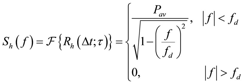 (8)
(8)
where  is channel autocorrelation function,
  is the average channel power,
  is the Doppler shift in direction of travel for path
  and
and  is the channel response in relation to Doppler shift.
3. Orthogonal Frequency Division Multiple Access
The multiple access scheme is based on Orthogonal Frequency Domain Multiplexing (OFDM) [9]. The multicarrier access is achieved by assigning a group of subcar-

Table 1. ITU pedestrian model [2].
riers to a particular user as shown in Figure 2. A typical subframe is shown in Figure 3. OFDMA is inherently robust to time dispersion on the radio channel without recourse to complex receiver channel equalisation due to the combine use of narrow-band subcarrier transmission with cyclic prefix (CP) [10]. Basically, OFDMA is a suitable data access technique of transforming wideband frequency selective channel into flat fading narrow bands [11]. OFDM signals can be generated by Inverse Fast Fourier Transform (IFFT) and Fast Fourier Transform (FFT) implementation at Node B and UE. Thus, the basic OFDM signal  can be expressed during the time interval
  as [2];
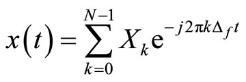 (9)
(9)
where  is the complex modulated symbol carried in
  subscriber in
  size subcarriers.
  is the subcarrier spacing and T is the symbol period.
As the downlink access standard prescribes [8],
 This is made constant regardless of the transmission bandwidth simplify the implementation of 3G multimode terminal [2]. Hence, for an N size FFT, the sampling rate fs is given by:
 (10)
(10)

Figure 2. LTE downlink frequency-domain structure [6].

Figure 3. LTE subframe [2].
Also the bandwidth is made scalable by controlling the size of N, keeping the subcarrier spacing constant. Thus, with FFT size varying from 128 to 2048, downlink bandwidth range up to 20 MHz can be supported [12]. Similarly, two CPs, a short duration 4.69 μs and long duration 16.67 μs [13] are defined for flexibility of LTE system deployment. CP insertion means that the last part of the OFDM symbol is copied and attached to the beginning of the symbol. The CP length is chosen to be longer than the maximum delay spread and is carried out to retain the orthogonal properties between the subcarriers, in order to avoid inter-channel interference ICI.
4. Implementation of Resource Allocation for OFDMA
The main objective of this work is to determine an optimal channel assignment to achieve an effective resource optimisation scheme for 3GPP Long Term Evolution downlink’s air interface which guarantees a designed coverage probability, high data rate, good spectral efficiency and ensure good quality of service. Allocation scheme has been modelled and presented. Resource optimisation is crucial to the overall performance of the proposed 3GPP LTE system. This methodology includes the system model of the developed optimisation scheme and as implemented using a simulation package known as MATLAB®. An initial model for all the modulation scheme is carried out in simple AWGN channel transmission, to test and evaluate the performance and detection of the modulated data as seen by the UE. Coherent detection is employed in the initial setup using Gray mapped signal constellation for all the modulation scheme and Maximum Likelihood Detection (MLD) at the receiver. Downlink transmission channel is characterised with multipath fading, dominance in frequency selectivity. A 6 ray ITU Pedestrian frequency selective channel B model (as shown in Table 1) is used to model the varying channel state. The signal arriving at the receiver is the sum of copies of the original signal with different delays and gain.
In the downlink of OFDMA systems, modulated data is converted from serial to parallel and mapped to different subcarriers. IFFT of the mapped data is carried out to convert the data into their corresponding time domain and the output signal are converted back to serial data called OFDM symbols. CP is attached to the beginning of the symbols (as guard interval, elimination of ISI and to enable circular convolution) before transmitting across the channel. At this point, a convolution with the channel is performed and Gaussian distributed noise n added. Subcarrier spacing in LTE is 15 kHz, CP length 4.69 μ or 16.67 μs and 1 ms time unit sub-frame (Table 2).
The description of OFDMA implementation above is in time domain, but OFDMA transmission in Frequency domain is exploited in this model making it relatively easier to implement frequency selective scheduling as 3GPP LTE standard prescribes. Therefore, OFDMA symbol implementation scheme can be described with the following analysis as described by Figure 4. Assume a Node B transmits symbols  which is passed through OFDM modulator yields OFDM symbols x as the output:
 (11)
(11)
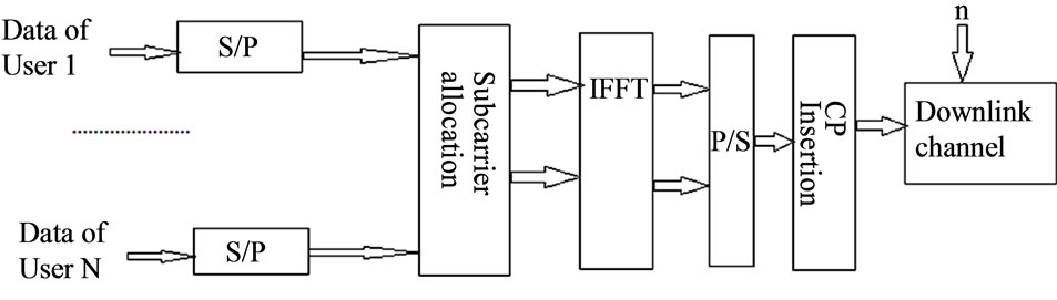
Figure 4. OFDMA downlink of 3GPP LTE [15].

Table 2. LTEOFDM parameters [14].
in the presence of noise n produce the received signal r at the receiver before demodulation is
 (12)
(12)
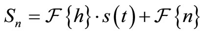
Demodulating r yields Sn
 (13)
(13)
 (14)
(14)
 (15)
(15)
 (16)
(16)
where Sn are the received OFDMA symbols of n size FFT.
Therefore, frequency domain OFDMA modulation implementation overcomes the rigorous time domain implementation in. For correctness, the simulated OFDM model performance is compared with its expected performance of converting frequency selective fading channel to flat fading channel of the same distribution.
4.1. Optmisation Scheme for Resource Allocation
The main challenge is to develop a scheme that will increase the throughput. In this work optomisation of the resources becomes necessary by developing subscriber allocation capable of optmising the channel allocation. Two schemes are possible which are fixed and dynamic.
A. Subcarrier Allocation
In OFDMA systems, resources are mapped to the available subcarriers. The allocation strategies employed in assigning the subcarriers will affect the system performance in various ways such as data rate, power efficiency, spectrum efficiency and bandwidth flexibility. Two main assignment strategies is exploited in this work and presented below.
B. Fixed Subcarrier Allocation
Fixed allocation algorithm allocates a set of subcarriers to each User Equipment (UE) and no other UE can use them even if they are not in use. This is often viewed as being fair to all users and ensures that all users have a dedicated channel when the need arise. But this method amounts to waste of resources if UEs are in deep fade or when UE is not in need of the allocated subcarriers. Thus, the fixed allocation can be model as follows:
Assume Node B is scheduled to transmit N size subcarrier to k numbers of UEs, each user is allocated subcarrier sets M adjacent to each other. The algorithm is modelled as shown in (17) and (18):
 (17)
(17)
 (18)
(18)
where  is the set of subcarriers allocated to the
  user, n is the number of allocated subcarriers,
  is the subcarrier index of the first subcarrier allocated to the
  user in the OFDM subcarrier stream of N size.
C. Dynamic Subcarrier Allocation
Since, subcarriers are currently spread across the channel band with equal spacing at implementation of OFDM, each OFDM symbol occupies a subcarrier (consisting of instantaneous subchannel, hn for N size subcarriers). Recall that, 3GPP LTE specifies the use of CQI to estimate the UE performance per transmission subframe. Dynamic allocation relies on the knowledge of this estimate; hence the allocation scheme is modelled as follows:
Assume the Channel Quality of Information (CQI) of independent UE is known at Node B, which comprise of the same channel characteristics of the transmission channel but varies per transmission time. The varying CQI Hq for the kth UE can be model as random instantaneous channel gain Hq,k by taking the frequency response of the randomly generated channel of the same delay profile as the transmission channel in n subcarrier transmission, which is expressed as:
 (19)
(19)
where  is the instanteneous subchannel extracted from
  UE’s quality indication at the instant time t of subcarrier n over
  subchannel of each UE (frequency response iteration of the randomly generated channel for each UE) within an OFDM data steam period T (T = tN). To apply CDS, in allocating resources to the UE with best CQI-essentially the best channel condition. The
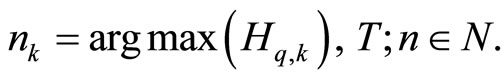
  UE that get the nth subcarrier needs to maximize the following function:
 (20)
(20)
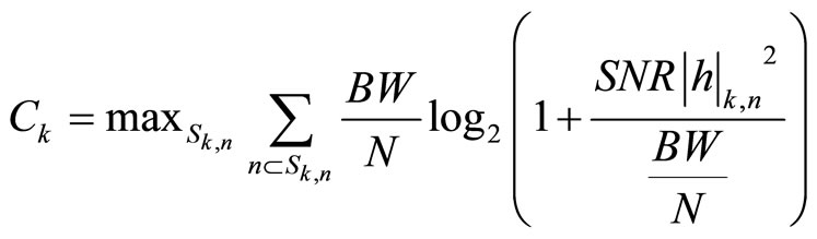
where nk is the subcarrier to be allocated to the  user having Hq,k that fulfils the condition above. Using the known Channel Quality of Information (CQI) from equation 20, Node B applies the nth subcarrier to the corresponding UE. Let Sk,n denote the set of n subcarriers assigned to the kth UE. Thus, a (K X N) state matrix of subcarriers S and subchannels H is formed. If n is allocated to a k user, it returns a value and index the corresponding hn in H, while returning false (0) for other users column-wise. Then, Sk,n can easily be extracted row-wise. The objective of this dynamic allocation algorithm is to find a good allocation that will optimise the available resources. More subcarriers are allocated to best UE for optimal performance and a subcarrier can only be used by at most one user. Each subcarrier n as perceived by user k is subject to flat fading. Therefore, user capacity Ck, can be formulated and simplified from the description in equation in accordance with Shannon equation [5] as:
 (21)
(21)
As also described for a power constrained system, Ck will be subject to [16]
 (22)
(22)
where Pmax is the maximum transmit power of the system,  is the channel gain of subcarrier n of the kth UE. BW is the transmission channel bandwidth occupied by N size subcarriers
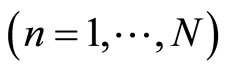 . SNR is the received Signal to noise power and N0 is the noise power.
4.2. Simulation Results and Analysis
To evaluate the performance of the optimisation scheme, a Monte Carlo simulation approach of the model in MATLAB, using 32 uniformly distributed UE (i.e. 32 users) is carried out within a given cell. The channel model is as described for ITU and for 5 MHz channel bandwidth with N = 512 size FFT as illustrated in Table 2 is implemented.
The numbers of users is made sufficiently large to exploit frequency selectivity gain and multiple of the user signals can undergo independent fading. For variationsCQI is estimated and all the subcarriers are allocated accordingly. OFDMA is expected to transform the channel from frequency selective Rayleigh fading to Flat fading. Provided below is the BER performance of simulated OFDMA in each modulation scheme as compared with a theoretical Rayleigh Flat fading.
Subcarrier Allocation Effects on Capacity
Since the downlink broadcast channel is characterised with fading, the transmission channel have independent random subchannel that changes over time [5]. Thus, the capacity of the downlink was estimated from which is known at the Node B according to the allocated subcarriers per UE as expressed in Equation (21). Capacity simulation results for 512 subcarriers adaptively allocated to 32 users over 5 MHz bandwidth.
The BER performances of the Bandpass modulation Techniques with OFDM in frequency selective fading channel were compared to the Bandpass modulation in flat fading channel. The results are presented in Figure 5 to Figure 8. It was observed that the performance of OFDM in selective fading channel produced equivalent bandpass modulation performance in a flat fading channel. In addition the throughput rate increased with dynamic allocation scheme which responds to the UE request as shown in Figure 9. The spectral efficiency is dependent on the subcarriers allocation scheme adopted as established in Figure 10. The resources optimization shows the subcarrier allocation with efficient allocation of radio resources as determined by the choice of modu-

Figure 5. Comparison of BER performance of simulated QPSK OFDMA in frequency selective channel and theoretical QPSK in flat fading channel.

Figure 6. Comparison of BER performance of simulated 8PSK OFDMA in frequency selective channel and theoretical 8PSK in flat fading channel.

Figure 7. Comparison of BER performance of simulated 16QAM OFDMA in frequency selective channel and theoretical 16QAM in flat fading channel.

Figure 8. Comparison of BER performance of simulated 64QAM OFDMA in frequency selective channel and theoretical 64QAM in flat fading channel.
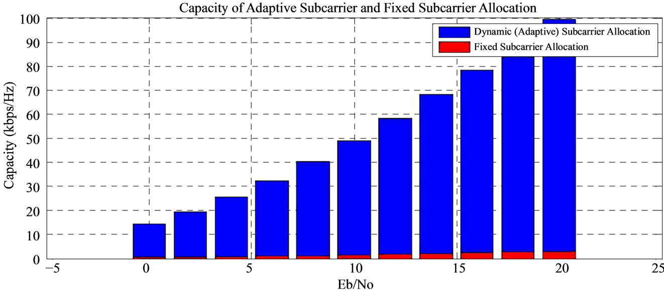
Figure 9. Grouped Spectral efficiency and Fixed Subcarrier Allocation vs Average SNR.

Figure 10. Spectral efficiency of adaptive and fixed subcarrier allocation vs SNR.

Figure 11. Comparison of subcarrier throughput rate with SNR.
lation. This is dynamically handled based on the channel quality information (Figure 11).
5. Conclusion
Efficient allocation of scarce radio resources is important for 3GPP LTE to provide high data rate transmission with improved spectral efficiency and guaranteed quality of service as the Next Generation network. Simulation results show that for an optimised resource allocation in the downlink, the inherent characteristics of a communi cation channel can be exploited and combined with the robustness of OFDMA to optimally allocate the radio resources. It was observed that optimal channel assignment of the dynamic allocation scheme exploited in this work is suitable for high data rate and spectral efficiency, and provides the required support for the increasing user demands encountered in the proposed 3GPP LTE downlink.
REFERENCES
- T. S. Rappaport, “Wireless Communications: Principle and Practice,” 2nd Edition, Prentice Hall, Upper Saddle River, 2002.
- D. So, “Mobile and Wireless Communication,” Communications Engineering Lecture Notes, University of Manchester, Manchester, 2010.
- A. Goldsmith, “Wireless Communications,” Cambridge University Press, Cambridge, 2005. http://dx.doi.org/10.1017/CBO9780511841224
- J. Berkmann, C. Carbonelli, F. Dietrich, C. Drewes and W. Xu, “On 3G LTE Terminal Implementation-Standard, Algorithm, Complexities and Challenges,” IEEE Wireless Communications and Mobile Computing Conference, Crete Island, 6-8 August 2008, pp. 970-975.
- E. Dahlman, S. Parkvall, J. Skold and P. Beming, “3G Evolution: HSPA and LTE for Mobile Broadband,” 1st Edition, Elsevier Academic Press, Amsterdam, 2007.
- H. Schulze and C. Luders, “Theory and Application of OFDM and CDMA,” John Wiley, Hoboken, 2005. http://dx.doi.org/10.1002/0470017406
- D. D. Bevan, V. T. Ermolayev, P. M. Grant, A. G. Flaksman and I. M. Averin, “Gaussian Channel Model for Macrocellular Mobile Propagation,” European Signal Processing Conference, Antalya, 4-8 September 2005.
- 3GPP, “TS 36.104 v8.0 (Release 8 Series) BS Radio Transmission and Reception,” 2010. http://www.3gpp.org/ftp/Specs/html-info/36-series.htm
- A. Furuskar, T. Jonsson and M. Lundevall, “The LTE Radio Interface-Key Characteristics and Performance,” 19th IEEE Personal, Indoor and Mobile Radio Communications, Cannes, 15-18 September 2008, pp. 1-5.
- D. Astely, E. Dahlman, A. Furuskar, Y. Jading, M. Lindstrom and S. Parkvall, “LTE: The Evolution of Mobile Broadband,” IEEE Communications Magazine, Vol. 47, No. 4, 2009, pp. 44-51. http://dx.doi.org/10.1109/MCOM.2009.4907406
- H. Schulze and C. Luders, “Theory and Application of OFDM and CDMA,” John Wiley, Hoboken, 2005. http://dx.doi.org/10.1002/0470017406
- S. Omar, A. Ancora and D. T. M. Slock, “Performance Analysis of General Pilot-Aided Linear Channel estimation in LTE OFDMA Systems with Application to Simplified MMSE Schemes,” IEEE Personal, Indoor and Mobile Radio Communications, Cannes, 15-18 September 2008, pp. 1-6.
- M. Sawahashi, E. Dahlman and K. Higuchi, “Evolved UTRA Technologies,” Enhanced Radio Access Technologies for Next Generation Mobile Communication, pp. 217-276.
- S. Ahmadi, “An Overview of 3GPP Long-Term Evolution Radio Access Network,” New Directions in Wireless Communications Research, Springer, Berlin, 2009.
- A. Haghighat, Z. Lin and G. Zhang, “Haar Compression For Efficient CQI Feedback Signalling in 3GPP LTE Systems,” IEEE Wireless Communications and Networking Conference, Las Vegas, 31 March-3 April 2008, pp. 819-823.
- W. Rhee and J. M. Cioffi, “Increase in Capacity of Multiuser OFDM System Using Dynamic Subchannel Allocation,” IEEE 51st Vehicular Technology Conference Proceedings, Vol. 2, Tokyo, 15-18 May 2000, pp. 1085- 1089.