World Journal of Mechanics
Vol.3 No.3(2013), Article ID:32835,10 pages DOI:10.4236/wjm.2013.33018
Performance Optimization of a Six-Strand Tundish
Department of Applied Mechanics, Indian Institute of Technology Delhi, New Delhi, India
Email: adewan@am.iitd.ac.in
Copyright © 2013 Siddharth Gupta, Anupam Dewan. This is an open access article distributed under the Creative Commons Attribution License, which permits unrestricted use, distribution, and reproduction in any medium, provided the original work is properly cited.
Received March 26, 2013; revised April 26, 2013; accepted May 5, 2013
Keywords: Tundish; Inclusion Removal; CFD; Euler-Lagrangian Approach; Turbulence Modeling
ABSTRACT
The aims of the present study are to predict and improve inclusion separation capacity of a six strand tundish by employing flow modifiers (dams and weirs) and to assess the influence of inclusion properties (diameter and density) together with velocity of liquid steel at the inlet gate on the inclusion removal efficiency of a six-strand tundish. Computational solutions of the Reynolds-Averaged Navier-Strokes (RANS) equations together with the energy equation are performed to obtain the steady, three-dimensional velocity and temperature fields using the standard k-ε model of turbulence. These flow fields are then used to predict the inclusion sepapration by numerically solving the inclusion transport equation. To account for the effects of turbulence on particle paths a discrete random walk model is employed. It was observed that with the employment of flow modifiers, the inclusion separation capacity of tundish increases without any large variation in the outlet temperatures. It is shown that inclusion properties and velocity are important parameters in defining the operating conditions of a six-strand tundish.
1. Introduction
Continuous casting processes dominate steel production the world over due to their significant advantages, i.e., considerable energy saving, small waste material, improved labor productivity and reduced pollution. Tundish is the final and most important unit of a continuous casting process in which the final processing with liquid metal can be done before it reaches the mould. Since it is the final unit, tundish serves as a reservoir for the mold which also helps to avoid splashing and removal of inclusions particles resulting from various metal air interactions together with other impurities present in the molten steel.
A large number of studies have been reported in the literature dealing with the physical and mathematical modeling of fluid flow condition together with the inclusion motion behavior inside a tundish for different tundish geometries and flow conditions. Raghavendra et al. [1] investigated the behavior of inclusion in a four-strand tundish using the software OpenFoam. They concluded that the tendency of getting trapped at the top surface is more for inclusions with higher diameter as compared to that for smaller diameter inclusions. Singh et al. [2] studied the performance of a tundish possessing different sets of furniture using the residence time curve in a single-strand tundish. Zhang et al. [3] investigated the inclusion removal with the help of gas bubbling and concluded that bubbling affects large particles but tendency of floating out of small particle increases due to bubbling.
Yang et al. [4] used water model, mathematical modeling and industrial trials to design and optimize the configuration of a tundish. Hryb et al. [5] developed Eulerian and Lagrangian formulations to model particle transport in a turbulent flow. They concluded that Lagrangian formulation provides better physics as compared to Eulerian approach. Hou et al. [6] developed physical and mathematical methods for a swirling flow tundish and concluded that such tundishes have higher capacity for the inclusion removal as compared to that of a tundish equipped with turbulence inhibitors. Gang et al. [7] performed water modeling experiments and concluded that a tundish equipped with dam and turbulence inhibitors has a significant effect on the inclusion separation.
Lei and He [8] developed a three-dimensional, Eulerian-Lagrangian method to predict the dynamic growth of alumina inclusion in a continuous caster. They concluded that the cluster formation depends on turbulent flow which determines the inclusion growth mechanism. Zhang [9] used the k-ε model of turbulence to simulate the fluid flow within a single-strand tundish. He concluded that the stochastic model produces more accurate inclusion motion as compared to that by a non-stochastic model. He also concluded that the investigation of the residence time of particles in molten steel is not so meaningful for the motion of inclusions. Merder et al. [10] investigated flow inside a six-strand tundish with and without dam. They obtained residence time curves to verify whether tundish condition is suitable for non-metallic inclusion removal or not.
Tripathi and Ajmani [11] modeled three-dimensional fluid flow characteristics inside a six-strand tundish whose one side was curved and compared its performance with that of a delta shaped tundish. They concluded that the curved surface plays a strong role in improving the characteristics for inclusion flotation. Rogler [12] developed a mathematical model of inclusion removal by the gas bubbling and concluded that for better separation efficiency bubbles having diameter less than 1.0 mm should be used. Jha and Dash [13] used different models of turbulence and concluded that the standard k-ε model predicts flow properties closest to experimental measurements as compared to those using the RNG k-ε model. Therefore the standard k-ε model is used in the present study.
Morales et al. [14] used water modeling and mathematical simulation techniques to conclude that the presence of turbulenceinhibitors increases product quality in a four-strand bloom caster tundish. Zhang et al. [15] calculated the inclusion removal in a single-strand tundish with and without flow modifiers. They concluded that the collision of inclusion and adhesion to the solid surfaces also plays an important role in the removal of inclusions and flow control devices favor the inclusion removal. Miki and Thomas [16] developed mathematical models to predict the removal of aluminum inclusions from the molten steel for both isothermal and non-isothermal conditions in a single-strand tundish and compared their predictions with the experimental steel samples. They found that the non-isothermal model along with the random walk model was much more consistent as compared to the isothermal model. Therefore in the present study nonisothermal model along with random walk model is considered.
Zheng and Zhu [17] developed a new approach to estimate level fluctuations in a thick slab continuous casting mold with argon blowing. They observed that the level fluctuation occurs mainly near the nozzle wall and it increases with gas injected to the SEN. Ding et al. [18] plotted residence time curves to optimize the flow control devices in a single-strand tundish. They found that with an optimized geometry inclusions area ratio decreases by 32%. Yao et al. [19] investigated the influence of inclusions on fatigue strength of a powder metallurgy tool and observed that the inclusions having sizes more than 30 μm promoted the occurrence of sub-surface crack initiation and decreased the fatigue strength. Meijie et al. [20] showed, by using residence time curve, that the removal of small size inclusions from the molten steel increases with the help of argon blowing at the bottom of the tundish. From industrial experiments they concluded that the content of inclusions having diameters less than 20 µm decreases by 24% with proper blowing conditions.
Most studies reported in the literature deal with singlestrand tundishes. The present study deals with a multistrand tundish. Such tundishes are being increasingly used in continuous casting processes. Many studies reported in the literature use the residence time curves to predict the inclusions behavior inside the tundish. In the present study Lagrangian motion of inclusions is tracked and it provides a good insight into the behavior of tundish. The geometry of the tundish should be such that it separates maximum percentage of inclusions present in the molten steel. Being lighter than steel, inclusions can be removed by trapping at the top surface. The use of flow modifiers is reported to promote the flow field towards the top surface which increases the inclusion removal efficiency of a tundish. The arrangement of flow modifiers used for enhancing inclusion separation efficiency should be such that temperature and percentage of inclusion at each outlet are nearly equal to produce the same quality of steel from each strand. Moreover, tundish should be subjected to modification only at the interior geometry and at the same time, it should not be expensive to fabricate.
With continuous research efforts over the last decade, computational fluid dynamics (CFD) has now become an effective tool for the design of steel tundishes. In the present study, 3-D, turbulent flow field in a six-strand trough type tundish is investigated using the standard k-ε model of turbulence. The finite volume based commercial software FLUENT 6.3.26 is used for performing the simulations. The flow fields thus obtained are used to predict the inclusion separation by numerically solving the inclusion transport equation, considering its drag and buoyancy forces. To simulate the chaotic effect of turbulent eddies on particle motion a discrete random walk model is used. The effects of flow modifiers, i.e., dam and weir, together with their height and molten steel stream velocity at the inlet gate on the inclusion motion (for different particle size and density) and outlet temperature of liquid steel have been investigated. The geometry of the multi-strand tundish is described in Section 2. The governing equations, turbulence model and boundary conditions are presented in Section 3. The code validation and results are presented in Section 4 followed by conclusions.
2. Physical Description of the Problem
The geometry of multi-strand tundish considered in the present study is taken from the study reported Merder et al. [10]. The tundish considered in the present study (Figures 1-3) is an example of trough-type tundish used for casting ingots employed for small cross-section rolled products, such as wire, rods, etc. Half of the tundish is shown because of the symmetry relative to the transverse plane passing through the inlet. The detailed constructional parameters are: L1 = 2785 mm, L2 = 2700 mm, L3 = 300 mm, L4 = 500 mm, L5 = L6 = 1000 mm, W1 = 1040 mm, W2 = 850 mm, W3 = 640 mm, W4 = 450 mm and steel bath height H = 740 mm. The inlet and outlet diameters of the gate are taken as 66 mm and 14 mm, respectively [10].

Figure 1. Geometry of six-strand trough type tundish considered in the present study.

Figure 2. Top plane view of the tundish.
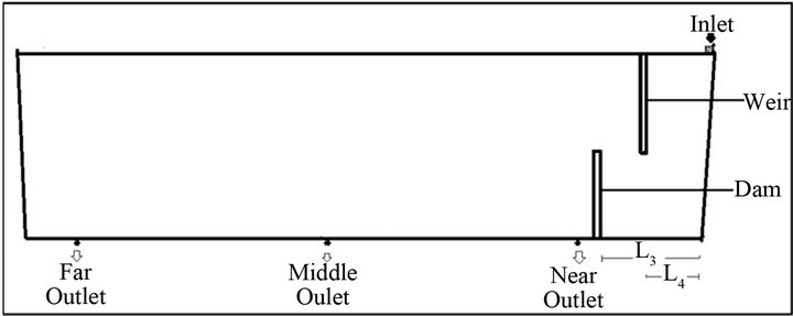
Figure 3. Front plane view of the proposed six-strand tundish with flow modifiers.
Figure 3 shows the proposed tundish with the flow modifiers. The dimensionless height (h*) is defined as the ratio of dam/weir height (h) to the bath height of the tundish (H). In all the cases considered in the present paper, the height of the dam measured from the bottom and the height of the weir measured from the top surface were taken to be the same. Here F.O. refers to the far outlet strand, M.O. to the middle outlet strand and N.O. to the near outlet strand. Four different values of h* (0, 0.25, 0.5, 0.75) were used to study the effect of height on the inclusion removal efficiency of the tundish. The values of the properties of liquid steel used are [10]: specific density = 7010 kg/m3, specific heat = 821 J/kg·K, thermal conductivity = 30.5 W/m·K and viscosity = 0.007 kg/m·s.
3. Mathematical Formulation
3.1. Governing Equations
The mathematical formulation used for modeling the flow of the liquid steel inside the tundish includes [21].
Continuity Equation
 (1)
(1)
Momentum Equation
 (2)
(2)
where, 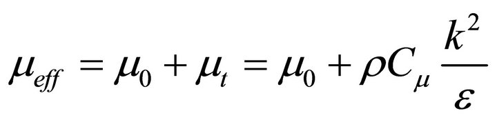
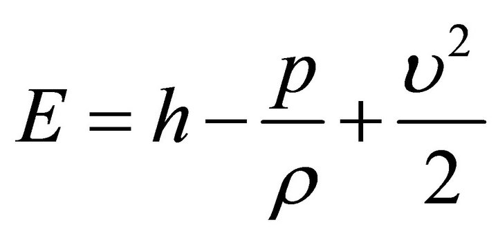
Energy Equation
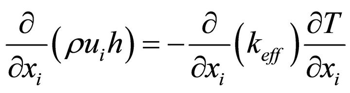 (3)
(3)
where, 
One of the challenges in the simulation of the flow in a steel tundish is an accurate modelling of the fluid turbulence and for this purpose we have used the standard k-ε model [21], which is a two equation turbulence model. In the k-ε model, two transport equations, one for the turbulent kinetic energy (k) and other for its dissipation rate (ε) are employed to calculate the eddy viscosity. It is one of the most widely used turbulence models for industrial applications.
Turbulent kinetic energy
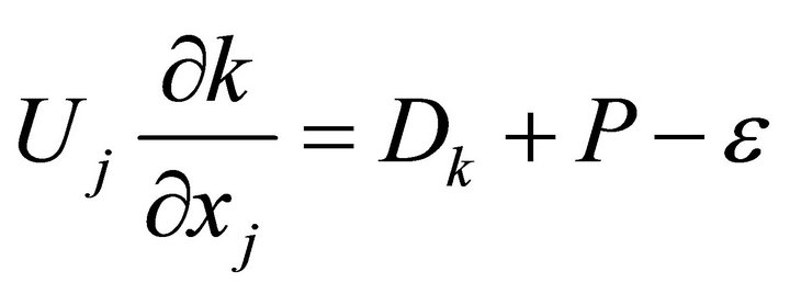 (4)
(4)
Rate of dissipation of turbulent kinetic energy
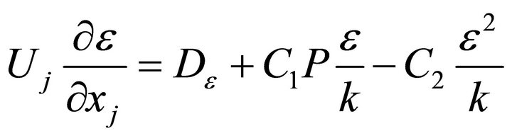 (5)
(5)
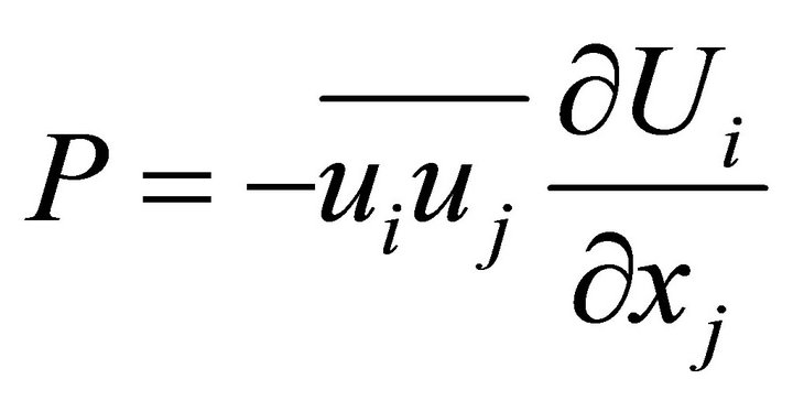
Reynolds stress is given by

where,


The values of the constants used in the k-ε model are C1 = 1.44, C2 = 1.92, σk = 1.0, σє = 1.3 and Cμ = 0.09 [21].
The first step in calculating fates of inclusions is to obtain appropriate velocity and temperature fields. To determine the distribution of temperature and velocity within a tundish, the partial differential Equations (1) to (5) were first solved numerically by employing the appropriate boundary conditions (discussed in Section 3.2). The inclusion trajectories were then calculated by using the Lagrangian frame of reference under the assumption that the inclusion-inclusion interaction and the effects on flow and temperature fields by inclusions are negligible.
The fates of inclusions were calculated by integrating the force balance on the inclusions and this can be written as [22]
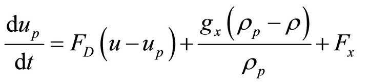 (6)
(6)
where, Fx denotes the additional acceleration (force/unit particle mass) term and FD (u − up) the drag force per unit particle mass.
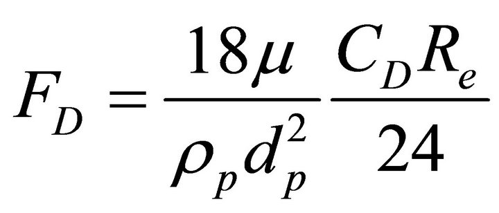 (7)
(7)
Here u denotes the liquid steel velocity, µ the molecular viscosity of the steel, ρ the steel density and up, ρp, dp the inclusion velocity, density, diameter, respectively. Re denotes the relative Reynolds number, which is defined as
 (8)
(8)
The dispersion of the inclusion due to turbulence in the liquid steel phase was predicted by using the stochastic tracking (random walk) model.
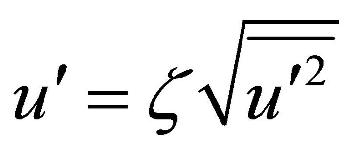
In the random walk model the particle motion is obtained by integrating the Equation (6) for individual particles, using the instantaneous fluid velocity, . Here,
  denotes the mean fluid phase velocity (liquid steel) and
  the fluctuating velocity component which is calculated under the assumption that it obeys a Gaussian distribution and is given by [22]
 (9)
(9)
where ζ denotes a normally distributed random number and the remainder of the right hand side is the local r.m.s. fluctuating components which can be defined as (assuming isotropy)
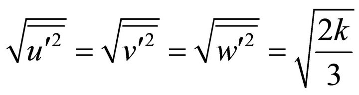 (10)
(10)
The inclusions were injected homogeneously through the inlet gate (equal to 520 inclusions in each case) and each inclusion’s trajectory was calculated until it got trapped at the top wall or exited from the tundish outlets.
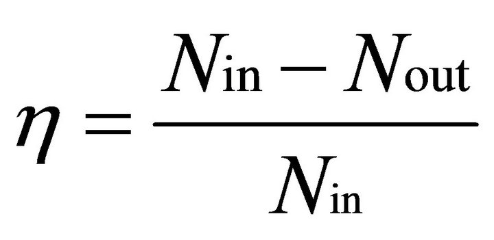
The overall and outlet strand efficiencies of the tundish can be defined as the ratio of the number of inclusions removed to the number of inclusions coming through the inlet gate of the tundish and is given by
 (11)
(11)
where, Nin denotes the number of particles coming into a tundish through the inlet gate and Nout is the total number of particles leaving the outlet gate.
3.2. Assumptions and Boundary Conditions
The flow was assumed to be steady and incompressible with no entrainments of air and gas by the incoming metal stream. The surface of the tundish was considered to be flat with an insignificant slag depth. The inclusions were assumed to be spherical which include the alumina based oxides. All the exogenous inclusions (having densities greater than that of steel) were ignored. In the present study micro inclusions were considered whose sizes vary between 1 µm to 100 µm and macro inclusions (size > 100 µm) were ignored.
The computed results were assessed for grid independence by considering 370,000, 319,000 and 180,000 elements. The average difference in the predicted values of the inclusion separation obtained between grid sizes of 180,000 and 319,000 was 6% and that between 319,000 and 370,000 was 2%. Therefore, in the present study, the 3-D computational grid includeed 319,000 control volumes with finer mesh at the inlet gate, strands and flow modifiers. The velocity at the inlet gate was taken as 0.9 m/s with turbulence intensity of 5% [10]. The no slip condition was employed on each wall surface with the zero velocity at the wall. The outflow boundary condition was taken at each outlet with mass flow weightage equal to one [10]. The top surface was assumed as a free surface with the zero shear stress. The acceleration due to gravity was taken as 9.81 m/s2.
For tracking inclusions trajectories, inclusions touching the top wall were assumed to be trapped and inclusions were reflected by all other walls including the flow modifiers [16]. Figure 4 shows different boundary conditions employed for the computations.
For the heat transfer calculation, the boundary conditions include the incoming liquid steel temperature as 1850 K. The heat losses were supposed to be taking place through the walls, bottom and free surface of fluid in the tundish. The top surface heat loss was taken as 15,000 W/m2 and from the tundish bottom and walls the heat loss was taken as 2600 W/m2 [10]. The SIMPLE algorithm was used for the pressure-velocity coupling and QUICK scheme was used for the discretization of momentum, energy, turbulent kinetic energy and turbulent dissipation rate equations.
4. Results and Discussions
4.1. Validation
Before performing the present computations, a validation study was carried out against the computed results reported by Merder et al. [10] who considered unsteady casting process using steel followed by its replacement by a new grade steel (having properties same as that of steel) for a six-strand bare tundish. They generated characterstics plot for the new grade steel until its mass fraction became unity and studied the average mass fraction of new grade steel against the flow time for each outlet strand. Figure 5 compares the mixing time characterstics
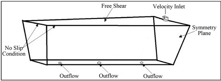
Figure 4. Geometry of the multi strand tundish showing different boundary conditions.

Figure 5. A comparison of the present mixing time characteristics for the far outlet (a), middle outlet (b) and near outlet (c) with those reported by Merder et al. [10].
for three outlet strands from the present computations and those reported by Merder et al. [10]. A good agreement is observed between the two (Figure 5). A validation of the inclusion removal was also carried out against the results reported by Mikki and Thomas [16]. They carried out numerical simulations on inclusion removal in a single-strand tundish using the standard k-ε model and the random walk model for tracking the trajectories of the inclusions inside a single-strand tundish. A good agreement between the present predictions of inclusion separation and those reported by Mikki and Thomas [16] can be observed in Figure 6" target="_self"> Figure 6.
4.2. Effect of Flow Modifiers
Table 1 shows the effect of flow modifiers on the inclusion removal efficiency of the tundish at each strand. For comparison of inclusion removal efficiencies of different tundishes considered, inclusions size was taken as 40 µm with density of 5000 kg/m3. The reason for choosing the value of the inclusion density as 5000 kg/m3 was based on the observation of Mikki and Thomas [16] who concluded that the average density of inclusions inside the tundish were approximately equal to 5000 kg/m3.
It can be seen from Table 1 that with the presence of flow modifiers (dam and weir) the inclusion removal
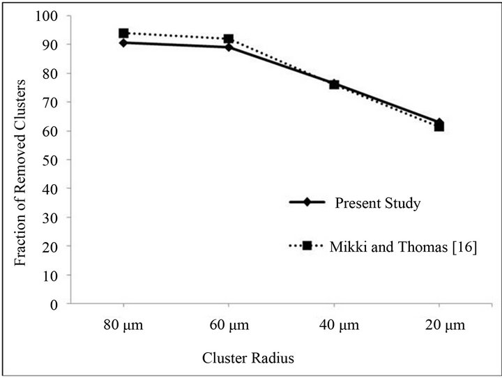
Figure 6. A comparison of the present inclusion removal with results reported by Mikki and Thomas [16].
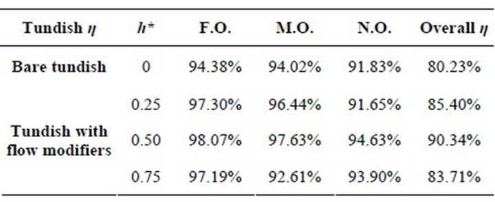
Table 1. Effect of flow modifiers on inclusion removal efficiency of each strand and overall efficiency of the tundish (inclusion size 40 µm, density 5000 kg/m3).
efficiency of the tundish increases. This is true for all the cases considered in the present study. With an increase in the dam and weir non-dimensional heights h* from 0.25 to 0.5 the overall removal efficiency of the tundish increases while further increase in height to 0.75 causes a decrease in the overall removal efficiency of the tundish. The same tendency is shown at each outlet strand. This shows that there is an optimal height of the dam and weir for which inclusion removal efficiency of tundish reaches the maximum value.
Further, it can be seen from Table 1 that the percentage of inclusion removal from each strand is different. The difference of inclusion removal percentage from each outlet strand appears more in case of tundish with flow modifiers. There is a marginal decrease in the percentage of inclusion removal from near outlet strand in tundish with h* equal to 0.25 and from middle outlet in tundish with h* equal to 0.75 as compared to that in a bare tundish. For a steel developer a given tundish will be ideal when the number of inclusions coming out from each strand is equal. Thus, it is very important to have minimum variation in the number of inclusions coming out from each strand. Tundish with dam and weir heights (h*) equal to 0.5 shows the lowest variation among different tundishes with flow modifiers considered in the present study. At the same time it provides the maximum overall inclusion removal efficiency. Therefore it can be concluded that the tundish with flow modifier having non-dimensional height (h*) of 0.5 is the best for the inclusion removal from a six-strand tundish.
An increase in the removal efficiency of the tundish can be understood with the help of velocity vector field drawn at a plane passing through the outlet gate of the bare tundish (Figure 7) and tundish with flow modifiers with varying h* (Figures 8-10). With the presence of dam a circulation region is produced before the near outlet causing a large change in the pattern of the velocity flow field which directs inclusions towards the top surface due to which number of inclusions trapped at the top surface increases. A tundish with flow modifiers of height h* equal to 0.25 is less efficient as compared to the value of 0.5 considered which is due to the fact as the height of weir is reduced it cannot sustain eddies created by dam due to which a high re-circulatory zone is produced closer to the near outlet strand causing more number of inclusions to pass through it (Figure 8). With an increase in the height of flow modifiers (h* equal to 0.5) a uniform flow field is produced with re-circulatory zone away from the near outlet causing an increase in the tendency of the inclusions to flow towards the top surface. Hence, inclusion removal increases. A further increase in the height (h* equal to 0.75) creates a large re-circulatory region prevailing over the middle and far outlets causing large number of inclusions to pass through the outlet strands (Figure 10).
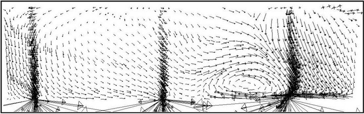
Figure 7. Velocity vector field drawn at a plane passing through the outlet gate of bare tundish.

Figure 8. Velocity vector field drawn at a plane passing through the outlet gate of tundish with flow modifier non-dimensional height (h*) equal to 0.25.
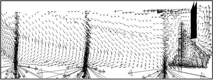
Figure 9. Velocity vector field drawn at a plane passing through the outlet gate of tundish with the flow modifier non-dimensional height (h*) equal to 0.5.

Figure 10. Velocity vector field drawn at a plane passing through the outlet gate of tundish with the flow modifier non-dimensional height (h*) equal to 0.75.
4.3. Effect of Inclusion Size and Density
Figures 11 and 12 show variation in inclusion separation efficiency of tundish with a change in the inclusions diameter and density. Four different inclusion sizes (20 µm, 40 µm, 60 µm, 100 µm) and densities (5000 kg/m3, 3000 kg/m3, 1500 kg/m3) were considered in the present study.
With an increase in the inclusion size the removal efficiency of the tundish increases (Figure 11). This is true for both bare tundish and tundish with flow modifiers. The present results are consistent with the observations of Mikki and Thomas [16] and metallographic microscope observations of Zhang et al. [15] for a singlestrand tundish. An increase in the removal efficiency of the tundish with an increase in the inclusion size can be explained with the help of Equations (6) and (7) governing the behavior of inclusions. With an increase in the inclusion size, the magnitude of the drag force in the governing Equation (6) decreases and thus less number of inclusions follows the flow stream and get trapped on the top surface of the tundish causing an increase in the removal efficiency of the tundish.
Inclusions with different sizes behave differently with a change in their densities (Figure 12). The inclusions

Figure 11. Variation in the inclusion removal efficiency with a change in the inclusion size.
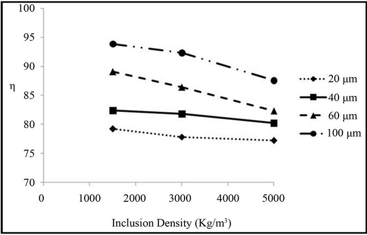
Figure 12. Variation in the inclusion removal efficiency with a change in the inclusion density.
having sizes greater than 40 µm are influenced more with a change in their densities compared to those with sizes less than 40 µm. For large inclusions with a decrease in their densities, the gravitational term in Equation (6) plays an important role and forces more number of inclusions to travel towards the top surface of the tundish and this behavior increases the removal efficiency of the tundish. For the smaller inclusions the drag term still dominates over the gravitational term causing more number of inclusions to flow with the liquid steel. Thus for smaller inclusions (<40 µm) a change in density does not produce any significant effect on the overall removal efficiency of the tundish.
4.4. Effect of Inlet Stream Velocity
The inlet stream velocity of the liquid steel plays an important role in the inclusion removal efficiency of the tundish. For assessing the effect of inlet velocity on the inclusion removal efficiency of the tundish, three different velocities (0.6 m/s, 0.9 m/s and 1.2 m/s) were considered. For all the considered velocities turbulent intensity of 5% was used. With an increase in the diameter of inclusions, the effect of the inlet stream velocity on the inclusion removal efficiency increases (Figure 13) and for the same inclusion size an increase in the inlet velocity leads to a reduction in the inclusion removal efficiency. This behavior is due to an increase in the momentum transfer towards the outlet strand gate which increases the number of inclusions to pass through outlet strands of the tundish.
4.5. Effect on Outlet Strand Temperatures
Table 2 shows the effect of flow modifiers on the outlet temperature at each strand of the tundish and Figure 14 shows the effect of velocity of liquid steel at the inlet on the outlet strand temperature of the bare tundish. It can be observed from Table 2 that with the employment of flow modifiers there is negligible change in the tempera-

Figure 13. Effect of inlet liquid steel velocity on the inclusion removal efficiency of the tundish.
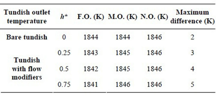
Table 2. Effect of flow modifiers on the outlet strand temperature of the tundish.

Figure 14. Effect of inlet velocity on the outlet strand temperature.
ture at different outlet strands. An increase in the height of the flow modifier causes an extremely marginal decrease in the temperature at far outlet strand, an extremely marginal increase in the temperature at the middle outlet strand and there is no change in temperature at the near outlet strand. The velocity of the liquid steel at the inlet gate also affects the outlet strand temperature of the liquid steel (Figure 14). With an increase in the velocity of the liquid steel at the inlet gate, loss of thermal energy inside the tundish decreases. Moreover, an increase in the velocity causes a decrease in the band width of temperatures prevailing in different outlet strands of the tundish.
5. Conclusions
A mathematical modeling technique is used for investigating the effect of flow modifiers on the inclusion removal efficiency of a six-strand tundish. Different velocities of liquid steel at inlet gate, heights of flow modifiers, different densities together with different sizes of inclusions have been considered to assess their effects on the inclusion removal efficiency and outlet strand temperature of the tundish. The following conclusions may be drawn from the present study 1) With the employment of flow modifiers, the inclusion removal efficiency of the tundish increases. The efficiency of the tundish reaches the maximum value for the dimensionless height of flow modifiers equal to 0.5.
2) It was observed that the removal efficiency of the tundish reduces with a decrease in the inclusion size.
3) There is no significant effect on the inclusion removal by a change in the density for the inclusions hav ing sizes less than 40 µm. However, for bigger inclusions with sizes more than 40 µm a decrease in the inclusion density causes an increase in the inclusion removal efficiency of the tundish.
4) The velocity of liquid steel at inlet gate plays an important role in the operating conditions of the tundish. With a decrease in the inlet velocity, the removal efficiency of the tundish for large inclusions increases but simultaneously it decreases the outlet strand temperature of the liquid steel.
In the present investigation adhesion of small inclusions to the wall, inclusion breakage and coalescence were not taken into account and these effects can cause a reduction of the inclusion separation efficiency by approximately 10% from those obtained in real situations.
REFERENCES
- K. Raghavendra, S. Sarkar, S. K. Ajmani, M. B. Denys and M. K. Singh, “Mathematical Modelling of Single and Multi-Strand Tundish for Inclusion Analysis,” Applied Mathematical Modelling, Vol. 37, No. 9, 2013, pp. 6284- 6300. doi:10.1016/j.apm.2013.01.013
- V. Singh, S. K. Ajmani, A. R. Pal, S. K. Singh and M. B. Denys, “Single Strand Continuous Caster Tundish Furniture Comparison for Optimal Performance,” Ironmaking and Steelmaking, Vol. 39, No. 3, 2012, pp. 171-179. doi:10.1179/1743281211Y.0000000065
- M. J. Zhang, H. Z. Gu, A. Huang, H. X. Zhu and C. J. Deng, “Physical and Mathematical Modeling of Inclusion Removal with Gas Bottom-Blowing in Continuous Casting Tundish,” Journal of Mining and Metallurgy, Section B: Metallurgy, Vol. 47, No. 1, 2011, pp. 37-44.
- S. Yang, L. Zhang, J. Li and K. Peaslee, “Structure Optimization of Horizontal Continuous Casting Tundishes Using Mathematical Modeling and Water Modeling,” ISIJ International, Vol. 49, No. 10, 2009, pp. 1551-1560. doi:10.2355/isijinternational.49.1551
- D. Hryb, M. Cardozo, S. Ferro and M. Goldschmit, “Particle Transport in Turbulent Flow Using both Lagrangian and Eulerian Formulations,” International Communications in Heat and Mass Transfer, Vol. 36, No. 5, 2009, pp. 451-457. doi:10.1016/j.icheatmasstransfer.2009.01.017
- Q. Hou, Q. Yue, H. Wang, Z. Zou and A. Yu, “Modelling of Inclusion Motion and Flow Patterns in Swirling Flow Tundishes with Symmetrical and Asymmetrical Structures,” ISIJ International, Vol. 48, No. 6, 2008, pp. 787- 792. doi:10.2355/isijinternational.48.787
- L. J. Gang, Y. H. Cheng, L. Liu and W. X. Hua, “Water Modeling of Optimizing Tundish Flow Field,” Journal of Iron and Steel Research International, Vol. 14, No. 3, 2007, pp. 13-19.
- H. Lei and J.-C. He, “A Dynamic Model of Alumina Inclusion Collision Growth in the Continuous Caster,” Journal of Non-Crystalline Solids, Vol. 352, No. 36-37, 2006, pp. 3772-3780. doi:10.1016/j.jnoncrysol.2006.05.032
- L. Zhang, “Fluid Flow, Heat Transfer and Inclusion Motion in Molten Steel Continuous Casting Tundishes,” 5th International Conference on CFD in the Process Industries, Melbourne, 13-15 December 2006, pp. 1-11.
- T. Merder, J. Jowsa and A. Boguslawski, “The Analysis of the Conditions of Steel Flow in the Tundish Performed by a Numerical Methods,” Archives of Metallurgy and Materials, Vol. 50, No. 4, 2005, pp. 933-953.
- A. Tripathi and S. K. Ajmani, “Numerical Investigation of Fluid Flow Phenomenon in a Curved Shape Tundish of Billet Caster,” ISIJ International, Vol. 45, No. 11, 2005, pp. 1616-1625. doi:10.2355/isijinternational.45.1616
- J. P. Rogler, “Modeling of Inclusion Removal in a Tundish by Gas Bubbling,” Ph.D. Thesis, Ryerson University, Toronto, 2004.
- P. K. Jha and S. K. Dash, “Effect of Outlet Positions and Various Turbulence Models on Mixing in a Single and Multi Strand Tundish,” International Journal of Numerical Methods for Heat & Fluid Flow, Vol. 12, No. 5, 2002, pp. 560-584. doi:10.1108/09615530210434296
- R. D. Morales, J. de J. Barreto, S. Lopez-Ramirez, J. Palafox-Ramos, and D. Zacharias, “Melt Flow Control in a MultistrandTundish Using a Turbulence Inhibitor,” Metallurgical and Materials Transactions B, Vol. 31, No. 6, 2000, pp. 1505-1515. doi:10.1007/s11663-000-0035-x
- L. Zhang, S. Taniguchi and K. Cai, “Fluid Flow and Inclusion Removal in Continuous Casting Tundish,” Metallurgical and Materials Transactions B, Vol. 31, No. 6, 2000, pp. 253-266. doi:10.1007/s11663-000-0044-9
- Y. Miki and B. G. Thomas, “Modeling of Inclusion Removal in a Tundish,” Metallurgical and Materials Transactions B, Vol. 30, No. 4, 1999, pp. 639-654. doi:10.1007/s11663-999-0025-6
- S. G. Zheng and M. Y. Zhu, “Physical Modeling of GasLiquid Interfacial Fluctuation in a Thick Slab Continuous Casting Mold with Argon Blowing,” International Journal of Minerals, Metallurgy and Materials, Vol. 17, No. 6, 2010, pp. 704-708. doi:10.1007/s12613-010-0377-6
- N. Ding, Y. P. Bao, Q. S. Sun and L. F. Wang, “Optimization of Flow Control Devices in a Single-Strand Slab Continuous Casting Tundish,” International Journal of Minerals, Metallurgy and Materials, Vol. 18, No. 3, 2011, pp. 292-296. doi:10.1007/s12613-011-0436-7
- J. Yao, X. H. Qu, X. B. He and L. Zhang, “Effect of Inclusion Size on the High Cycle Fatigue Strength and Failure Mode of a High V Alloyed Powder Metallurgy Tool Steel,” International Journal of Minerals, Metallurgy and Materials, Vol. 19, No. 7, 2012, pp. 608-614. doi:10.1007/s12613-012-0602-6
- Z. Meijie, G. Huazhi, H. Ao, Z. Hongxi and D. Chengji, “Numerical Simulation and Industrial Practice of Inclusion Removal from Molten Steel by Gas Bottom Blowing in Continuous Casting Tundish,” Journal of Mining and Metallurgy B: Metallurgy, Vol. 47, No. 2, 2011, pp. 137- 147.
- A. Dewan, “Tackling Turbulent Flows in Engineering,” Springer, Berlin, 2011. doi:10.1007/978-3-642-14767-8
- “Fluent User Guide,” Fluent Inc., Lebanon, 2006.