 Journal of Power and Energy Engineering, 2015, 3, 443-448 Published Online April 2015 in SciRes. http://www.scirp.org/journal/jpee http://dx.doi.org/10.4236/jpee.2015.34060 How to cite this paper: Turan, O. and Aydin, H. (2015) Power System Analysis of an Aero-Engine. Journal of Power and Energy Engineering, 3, 443-448. http://dx.doi.org/10.4236/jpee.2015.34060 Power System Analysis of an Aero-Engine Onder Turan1, Hakan Aydin2 1Faculty of Aeronautics and Astronautics, Anadolu University, Eskisehir, Turkey 2TUSAS Engine Industries, Eskisehir, Turkey Email: onderturan@anadolu.edu.tr, tei.hakan@gmail.com Received January 2015 Abstract The aim of this study is analyzed in detail for better understanding of energy and power of an aero-engine. In this regard, this study presents energy equations were applied to the turbofan en- gine components. The engine has a thrust range of 82 to 109 kN. It consists of fan, axial low pres- sure compressor (LPC), axial high pressure compressor (HPC), an annular combustion chamber, high-pressure turbine (HPT) and low pressure turbine (LPT). The results show that power of the engine flow approaches a maximum value to be 82.85 MW in the combustor outlet, while mini- mum power is observed at LPC inlet with the value of 1.37 MW. Furthermore, important parame- ters of the engine are also analyzed from reverse-engineering method. It is expected that results of this study will be beneficial of power, cogeneration and aero-propulsive generation systems in similar environment. Keywords Aero-Engine, Gas Turbine , Energy, Power System, Cogeneration, Propulsion 1. Introduction Air travel is growing wit average of among all modes 5% to 6% per year. If this situation in air travel continues, world air traffic volume may increase five-fold to as much as twenty-fold by 2050 compared to the 1990 level and account for roughly two thirds of global passenger-miles traveled [1]-[3]. Current estimates show that global air traffic volume is growing so fast that total aviation fuel consumption and environmental effect will continue to grow despite future improvements in propulsion systems and airframe technologies [2]-[4]. In aviation, engine fuel consumption and aircraft impacts on the environment are two important areas of re- search. From an environmental perspective, using energy with high efficiency reduces pollutant emissions and harm to ecological systems. For a given output, less fuel is needed when efficiency increases and less waste is re- leased. These benefits lead to increased life times for energy resources and greater sustainability. Turbofan en- gines, in particular, have led to significant improvements in noise, fuel consumption, thrust and engine size [1] [2]. Historic trends in improving efficiency levels show that aircraft entering today’s fleet are around 80% more fuel efficient than the increasingly high bypass ratios [5 ]-[7]. Other way to propulsion system improvement is to increase turbine inlet temperature [8]. Therefore energy consumption plays a crucial importance role to achieve sustainable development [9] [10]. Through a literature review, it is noticed that there is no work to be studied about power system calculation 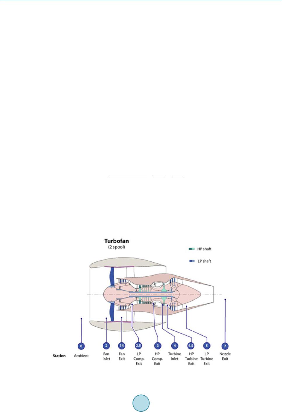 O. Turan, H. Aydin for a PW6000 turbofan engine in the open literatures. In this paper, the detailed power analysis of PW6000 tur- bofan engine has been performed. In this analysis, energy flows have been calculated at engine component sta- tions. 2. System Description An illustrated diagram, station numbering and main component of the PW6000 turbofan engine is shown in Figure 1. It consist of fan, axial low pressure compressor (LPC), axial high pressure compressor (HPC), an an- nular combustion chamber, high-pressure turbine (HPT) and low pressure turbine (LPT). It has 106 kN thrust force, 4.8 bypass ratio and 26.6 total pressure ratio. For the engine, the intake air mass flow rate of 290 kg/s, about 50 kg/s is taken into core of engine and about 15 kg/s air is burned along with 1.11 kg/s fuel in the com- bustion process. The fuel presently used in most civil aircraft is JET-A1 (kerosene), although similar other fuels are sometimes used. In this paper, kerosene is modeled as C12H23 [11] [12] which has a specific chemical exergy of 43.1 MJ/kg. The specific fuel consumption (SFC) at the maximum power is 10.67 g/(kN∙s). Thermal efficiency of the engine at for the tested engine parameters is 0.45. The maximum take-off thrust is 106 kN. 3. Parametric Study for Power Analysis Thermodynamic first -law analysis is energy-based approach in thermal systems. It is based on the principle of conservation of energy applied to the system. For a general steady state, steady-flow process, the four balance equa- tions (mass, energy, entropy) are applied to find the work and heat interactions, the rate of irreversibility, the energy and power efficiencies [9] [10] [13] [14] . In the schematic diagram of the high bypass turbofan engine given in Figure 1, the bypass ratio is defined as Bypass airflow Primary airflow fan cold core hot mm mm α == = (1) Thus if the air mass through the core (HPC) is , then the bypass air mass flow rate is . Now successive elements will be examined. Intake (I): The inlet conditions of the air entering the inlet are the ambient pressure and temperature ( ). The intake has an isentropic efficiency. For a flight Mach number of M0, then the temperature ratio and pres- sure ratio at the intake are given by the relations [15]: Figure 1. Main components of a turbofan engine power system [11].  O. Turan, H. Aydin ( ) /1 2 20 0 -1 12 cc tc II PM P γγ γ πη − == + (2) (3) where is the specific heat ratio for core stream and is the inlet isentropic efficiency. Fan: For a known fan pressure ratio and isentropic efficiency , then the temperature and pressure at the outlet of the fan given by the following relations [15]: (4) ( ) ( ) 1/ 17 2 1 1 cc fan tt fan TT γγ π η − − = + (5) 3.1. High Pressure Compressor (HPC) Similarly, both the high pressure compressor pressure ratio and isentropic efficiency are known. Thus, the temperature and pressure at the outlet of HPC are given by the following relations [15]: (6) () () 1/ 2.5 2 1 1 cc HPC tt HPC TT γγ π η − − = + (7) 3.2. Combustion Chamber (CC) The temperature at the end of the combustion process is generally known. The maximum temperature in the cycle, which is frequently identified as the turbine inlet temperature occurs here. The pressure at the end of combustion depends on the pressure drop in the combustion process itself. It may be expressed as [15]: (8) 3.3. High and Low Pressure Turbine (HPT and LPT) HPT and LPT drive HPC and fan, respectively. The energy balance for these spools per unit air mass flow rate is given by following relations [14]: and (9) 3.4. Exhaust Nozzle (EN) A nozzle isentropic efficiency of , the critical pressure is calculated from the relation [15]: ()() () ( ) 5 /1 1 11/1 /1 tt t cr EN tt P P γγ ηγ γ − = − −+ (10) Now if the exhaust nozzle is an ideal, then , the above equation is reduced to ( ) ( ) /1 5 1 2 tt t t cr P P γγ γ − + = (11) 3.5. Fan Nozzle (FN) The fan nozzle is also checked to determine whether choked or unchoked. Thus, the critical pressure is calcu- 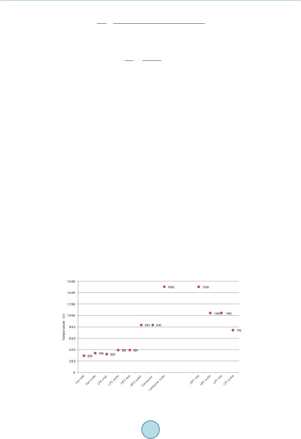 O. Turan, H. Aydin lated from the relation [15]: ()( ) () ( ) 17 /1 1 11/1 /1cc t cr FN cc P P γγ ηγ γ − = − −+ (12) If the fan nozzle is an ideal, then , the above equation will be reduced to [16]: ( ) ( ) /1 5 1 2 cc c t cr P P γγ γ − + = (13) The thrust of the turbofan engine is obtained by momentum of the burned gases. Thrust can be expressed as follows: ( ) ( ) () () 1909090 190 1 fanHPCEN FN Fm V VmfVVAPPAPP=−++ −+−+− (14) where f is the fuel-air ratio, V is the velocity, A is the area. 4. Results and Conclusions The relations given in this section are applied to the engine along with its components given in Figure 1 and following, which includes energy definitions from [16]. In gas turbine engines, a part of compressed air is ex- tracted to use for ancillary purposes, such as cooling, sealing and thrust balancing. Temperature values at inlet and outlet for the fan, HPC, combustor, HPT, LPT are given in Figure 2. Figure 3 also illustrates the pressure distribution of the fan, HPC, combustor, HPT, LPT at maximum power. In this study the cooling airflow is neglected since it doesn’t have meaningful effect on exergy and sustainability ana- lyses. In this study, the assumptions made are listed below: 1) The air and combustion gas flows in the engine are assumed to behave ideally; 2) The combustion reaction is complete; 3) Compressors and turbines are as- sumed to be adiabatic; 4) Ambient temperature and pressure values are 288.15 K and 101.35 kPa, respectively; 5) The energy analyses are performed for the lower heating value (LHV) of kerosene (JET A1) which is accepted as 42,800 kJ/kg (h) engine accessories, pumps (fuel, oil and hydraulic) are not included in the analysis. Combus- tion balance equation is calculated by following equation, 22 22 12 2322 22 0.7748 N12.027 CO 0.2059 O+13.25 HO CH 92.23 0.0003 CO+1.248 O 0.019 HO+71.46 N + +→ + + (15) Finally, Figure 4 also shows the energy flows at the inlet and outlet for the fan, HPC, combustor, HPT, LPT at Figure 2. Temperature distribution (K) of a turbofan engine power system components. 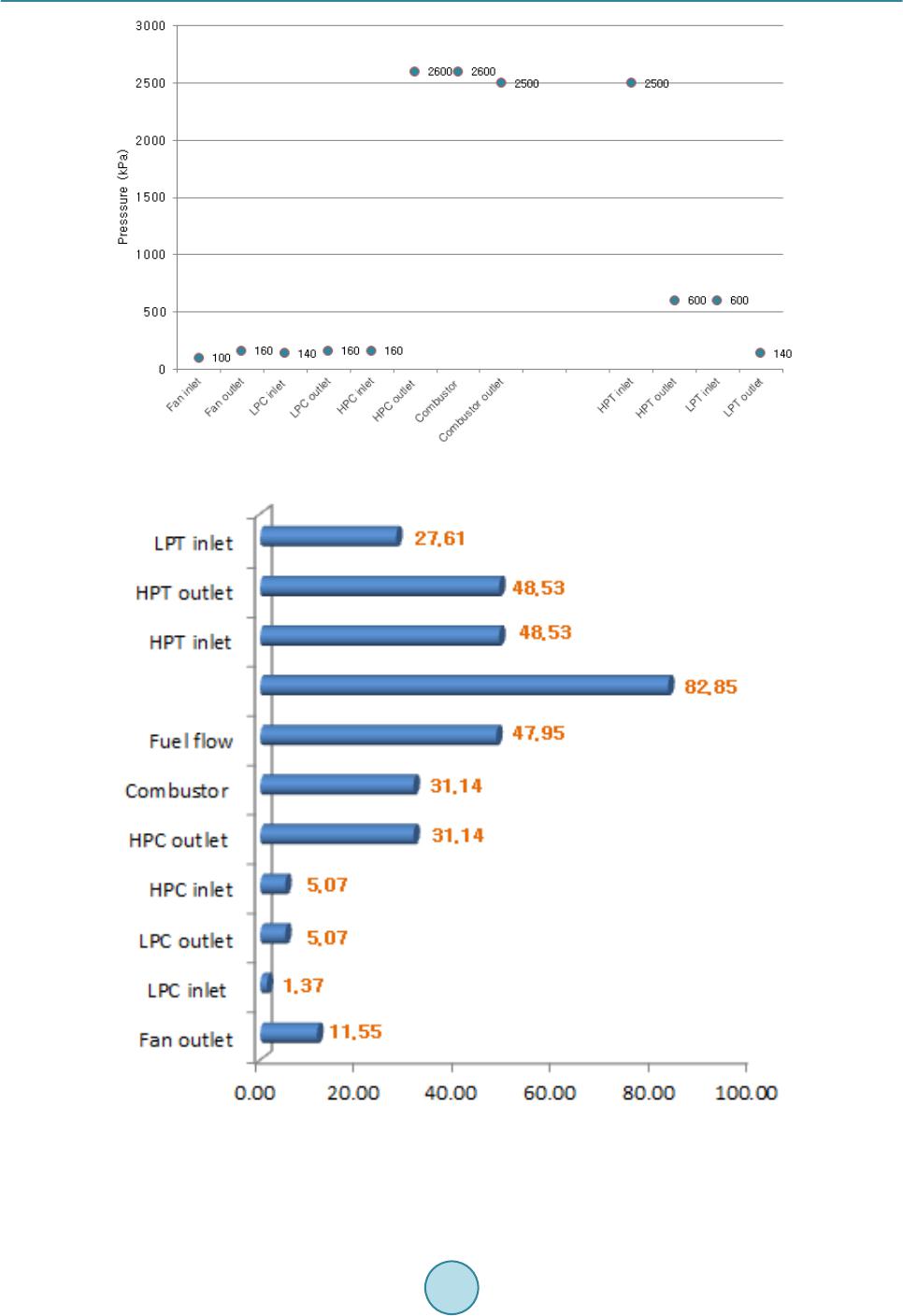 O. Turan, H. Aydin Figure 3. Pressure distribution (kPa) of a turbofan engine power system components. Figure 4. Power distribution of a turbofan engine power system components (MW). maximum power. Maximum energy flow is calculated in HPT inlet due to fuel energy with the value of 82.85 MW. On the oth-  O. Turan, H. Aydin er hand, energy flow is observed at LPT inlet (to be 27.61 MW) due to expansion process. The results should provide a realistic and meaningful in the thermodynamics first law evaluation of PW6000 turbofan engine, which may be useful in the analysis of similar propulsion systems as cogeneration and power system. A first law of thermodynamics can help improve the environmental performance of the aero derivative engine, and consequently should be considered in future assess men t s. Acknowledgements This study was supported by Anadolu University Scientific Research Projects Commission under the grant No: 1404F219. References [1] Gohardani, A., Georgios, S. and Doulgeris, R.S. (2010) Challenges of Future Aircraft Propulsion: A Review of Dist ri- buted Propulsion Technology and Its Potential Application for the All-Electric Commercial Aircraft. Progress in Aer- ospace Sciences, 47, 369-391. http://dx.doi.org/10.1016/j.paerosci.2010.09.001 [2] IPCC (1999) IPCC Special Report on Aviation and the Global Atmosphere. Intergovernmental Panel on Climate Change. [3] Aylesworth, J.H. (1996) Global Atmospheric Effects of Aviation: A Policy Perspective. Aerospace Industries Associa- tion of America. [4] Greene, D.L. (1995) Commercial Air Transport Energy Use and Emissions: Is Technology Enough? Conference on Sustainable Transportation—Energy Strategies. [5] En vir o (2011) http:// www.enviro.aero/Content/Upload/File/BeginnersGuide_Biofuels_Web [6] Peeters, P.M., Middel, J. and Hoolhorst, A. (2005) Fuel Efficiency of Commercial Aircraft: An Overview of Historical and Future Trends. NLR-CR-2005-669. [7] MIT (2011) http://web.mit.edu/airlines/analysis/analysis_airline_industry.html [8] http://www.pw.ut c.com/Ho me [9] Balkan , F., Colak, N. and Hepbasli, A. (2005) Performance Evaluation of a Triple Effect Evaporator with Forward Feed Using Exergy Analysis. International Journal of Energy Research, 29, 455-4 70. http://dx.doi.org/10.1002/er.1074 [10] Dincer, I., Hussain, M. and Al -Zah arnah , I. (2004) Energy and Exergy Use in Public and Private Sector of Saudi Ara- bia. Energy Policy, 32, 1615 -1624 . http://dx.doi.org/10.1016/S0301-4215(03 )00 13 2-0 [11] http://www.gknaerospaceenginesystems.com/aero/global/en-gb/products/Engine%20components/commercial_engines/ Pages/pw6000.aspx [12] Edwards, C.F. (2004) Development of Low-Irreversibility Engines. Energy Research at Stanford Report, 36. [13] Koroneos, C., Dompros, A., Roumbas, G. and Moussiopoulos, N. (2005) Advantages of Use of Hydrogen Fuel as Com- pared to Kero sene. Res ources, Conservation and Recycling, 44, 99-113. http://dx.doi.org/10.1016/j.resconrec.2004.09.004 [14] Wall, G. (2003) Exergy Tools. Proceedings Institution of Mechanical Engineering, 125 -13 6. [15] El-Sayed, A.F. (2008) Aircraft Propulsion and Gas Turbine Engines. CRC Press, UK. [16] Aydın, H., Turan, O., Hikmet Karakoc, T. and Midilli, A. (2014) Sustainability Assessment of PW6000 Turbofan En- gine: An Exergetic Approach. International Journal of Exergy, 14, 388-412. http://dx.doi.org/10.1504/IJEX.2014.061025
|