Journal of Electromagnetic Analysis and Applications
Vol.6 No.7(2014), Article
ID:47276,9
pages
DOI:10.4236/jemaa.2014.67018
Electromagnetism and the Arc Efficiency of Electric Arc Steel Melting Furnaces
A. N. Makarov, V. V. Rybakova, M. K. Galicheva
Tver State Technical University, Tver, Russia
Email: tgtu_kafedra_ese@mail.ru
Copyright © 2014 by authors and Scientific Research Publishing Inc.
This work is licensed under the Creative Commons Attribution International License (CC BY).
http://creativecommons.org/licenses/by/4.0/


Received 6 December 2013; revised 8 February 2014; accepted 10 March 2014
ABSTRACT
Results of analytically studied effect of electromagnetic blowing and the slag height on the arc efficiency are stated. An arc is blown from under an electrode toward the furnace walls under an electromagnetic force, arc radiation on the wall and roof increase and effective output, absorbed by the metal decreases. EAF (electric arc steel melting furnace) with independently powered arcs, eliminating its electromagnetic blowing is proposed. When arcs are powered independently, its efficiency increases significantly, and specific energy consumption decreases.
Keywords:Electromagnetic Forces, Arc, Heat Exchange, Electric Furnace

1. Introduction
Power consumption in EAF may be reduced by the increase in the arc efficiency of furnaces. Design procedure of the arc efficiency of furnaces is developed and stated. Calculations show that if we are to increase the arc efficiency and reduce the power consumption, we need to eliminate electromagnetic arc blowing.
At present, over 40% of all steel in the world are melted in arc steel-melting furnaces. Three-phase electro-arc-steel melting furnaces (EAFs) and dc electro-arc-steel melting furnaces (dc EAFs) are used for steel melting. In dc arc-steel melting furnaces with one roof electrode the arc glows vertically between electrode and metal bath at liquid stages of melting. In dc arc-steel melting furnaces the current doesn’t break and flows vertically in this way: roof electrode-electric arc-metal bath-bottom electrode. Electromagnetic buoyancy in dc EAF is lacking from the fact that current doesn’t change its direction.
In three phase arc-steel melting furnaces current breaks in metal bath at 90˚ and flows the way: roof electrode of a phase (b, c)-electric arc of a phase (b, c)-horizontally along top layers of metal bath-electric arc of b phase (c, a)-roof electrode of b phase (c, a). Since arc current breaks at 90˚, electromagnetic buoyancy acts on electric arc. Arc is blown out toward furnace wall by the action of electromagnetic buoyancy, its heat radiation on the wall increases and decreases on the metal, arc efficiency decreases. Since 90% of electric steel is made in EAF and 10% in dc EAF, it is very important to eliminate electromagnetic buoyancy in EAF.
2. Laws of Radiation and the Arc Efficiency of Steel-Melting Furnaces
2.1. Laws of Radiation Emitted by Ionized Gas Layers of Electric Arc
In arcs of EAFs 89% - 96 % of the power converts to the heat radiation flux [1] -[3] . When we determine the arc efficiency, it is necessary to know how radiation is distributed along heat surfaces-metal, wall, roof. Heat radiation flux of an arc to the metal is the specific heat flux as it is consumed usefully for heating and melting the metal. Radiation flux of an arc to the wall surfaces, roof is consumed for water heating in water-cooled wall panels and roof, and characterizes radiation power loss of an arc.
At figure 1, we presented isotherms of an electric arc at a current of 200 A, 50 mm length, glowing between carbon electrodes in the atmosphere. The first from the arc axis isothermal layer of 10,000˚C present cylinder gas volume, the following isothermal gas layers of 8000˚C - 3000˚C have cylinder part at anode and cone part at cathode.
Coaxing layers of ionized gas may be approximated by cylinder layers.
Such pattern of electric arc is character to all of the considered arcs, glowing in gases, vacuum, metallic vapors [1] -[4] .
Theory of radiative heat exchange in furnaces, fire-boxes, combustion chambers is based on Stefan-Boltzmann law, one of the main law of radiative heat exchange. The equation for calculating the radiation flow density of ionized and non-ionized gas layer to the heat surface based on Stefan-Boltzmann law acquires the form:
 (1)
(1)
where cs is blackbody radiation coefficient; εre—reduced emissivity; Tg, Tsur—gas and heating surface temperatures accordingly; φ12—angular coefficient of gas layer radiation onto the heat surface.
Some researches attempted to enforce Stefan-Boltzmann law for calculating radiative heat exchange in EAFs, but such attempts were not rewarded. Effective arc temperature in 3-t and 150-t furnaces is the same and accounts for about 6000˚C [1] . Hence, we obtain equal heat fluxes in 3-t either in 150-t furnaces from arcs onto the smelted metal and furnace capacity by the formula (1). However capacity of 3-t furnace is 1 t/h, and 200 t/h of 150-t and it isn’t determined by the temperature but the arc power, which is 0.4 MW in a 3-t furnace, 80 MW in 150-t furnace. Thus, until the early 80s there was no design procedure of heat exchange in EAF.
In 1979-1982 the author put forth the conjecture that radiation emitted by a plurality of isothermal coaxial

Figure 1. Isothermal coaxial layers formed in electric arc glowing..
gas-ionized layers of the arc may be simulated by radiation of central isothermal coaxial cylinder gas ionized layer. Based on this conjecture, the author had developed a method of heat exchange calculation for EAFs [5] [6] .
The conjecture was validated by calculations, experiments, EAF operating practice and, subsequently, the discovery of laws of radiation emitted by ionized and non-ionized gas layers of the electric arc and flame [7] . Laws of radiation of arc gas layers and flame are listed in detail in [8] [9] . During fuel flare 90% - 95% power generated in torch as heat flux.
Laws of radiation emitted by gas layers of electric arc and flame can be summarized as follows: Isochoric coaxial cylinder layers, formed the arc (flame) are characterized by equal thermal radiation indices: average beam path length and angular shell emission factor to a computational surface element.
Consequently, radiation from a plurality of gas layers onto the computational surface element can be substituted by the radiation from a single central layer located on the arc (flame) axis of symmetry and releasing as much radiation power as all plural shells of the arc (flame) in total.”
Thus, works [5] -[9] laid the foundation for arc rad flux distributive calculation on heating surfaces with allowance for electromagnetic depression and arc blowing, the fundamental basis for arc efficiency design procedure.
2.2. Electromagnetism in Arcs of EAFs
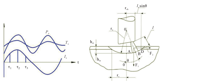
Let us consider in detail electromagnetism in arcs of EAFs (Figure 2). Current Ia, passing the electrodes, creates an electric arc blown under electromagnetic force on the periphery of electrode tip and on the surface of the metal bath; with this slag is thrown off to lined walls and slopes.
At the beginning of a current half-cycle τ1 (Figure 3(a)) an arc glows along the electrode axis, moves over the electrode as a cathode spot and over a metal bath depression as an anode spot in the half-period, and occupies position 16 by the middle of the cycle τ2 (Figure 2).
The arc current changes at a frequency of 50 Hz. Figure 3, a shows one arc cycle in glowing onto a liquid metal bath.
An arc current creates a magnetic field, which generates a compressive pressure on the arc column that is radially directed from the outer surface of the arc column of ra radius to its axis. Compressive pressure fcom at r distance from the arc axis is described by the expression [1] :
 (2)
(2)
where µ0 is the magnetic constant. The compressive pressure acts both radially and axially, generating axial force F1 on the liquid bath surface that forms a depression on it in which the arc is submerged (Figure 3(b)). When an arc submerges into the liquid bath, its open part, which emits a heat flow into the environment, decreases and the arc emission to the metal bath (including the metal surface in the depression) increases. The axial force is equal the integral in Equation (2) over the entire cross section of the arc column
 (3)
(3)
The arc current passes through the metal bath to the two other phases and creates a magnetic field and electromagnetic force F2 on the arc column toward the lining along the line where the electrode and the furnace wall are located at the minimum distance (Figure 3(b)). Deflecting force F2 “blows” the arc from below the electrode toward the lining and causes a sharp increase in the thermal load on the walls against the electrodes (so called hot zones). When the arc is blown, the shielding effect of the depression in the liquid bath weakens and the heat fluxes of the arc radiation to the walls and roof increase; that I’s, the arc power losses grow. As a result of blowing, the arc column is inclined at an angle θ = 45˚ - 60˚ to the electrode axis. Blowing angle θ depends on the electric current and the arc length: the higher the electric current and the longer the arc, the higher angle.
Deflecting force F2 can be approximately determined by the formula [1] :
 (4)
(4)
where µ is the magnetic permeability of the arc plasma and h is the distance to the electric axis of the current

Figure 2. A three-phase steel-melting furnace and power source. 1—primary winding of the transformer; 2—voltage step switch; 3—secondary winding of the transformer; 4—busbar bridge; 5—static shoes; 6—flexible cables; 7—slide shoes; 8— bus tubes; 9—a,b,c phase electrodes; 10—lined roof part; 11—water-cooled roof panels; 12—water-cooled wall panels; 13—powder carbon injection facility;14—gas-oxygen burner (GOB); 15—flame, formed during fuel burning; 16—electric arc moved by an electromagnetic force from the electrode axis to the periphery of the end of the electrode and to the metal bath surface (is absent in the furnace structure); 17—lined part of the walls and banks; 18—bottom tapping channel; 19— lined bottom ; 20—slagged molten bath; 21—electric arc glowing along the electrode axis.
 (a) (b)
Figure 3. Changes in the instantaneous values of electric current, temperature, and arc power in time τ (а); Electrodynamic phenomena and geometric constructions for calculating the heat exchange in EAF (b) hsl—slag height; h3—depth of indentation in a metal.
carrying layer in the liquid metal (3.2 - 3.6 cm for EAF) [1] .
At the end of the stage of melting, the arc length is maximal during operation at the maximum voltage and deflecting force F2 is also maximal. The experience shows that deflecting force F2 can be counterbalanced by axial force F1 in short arcs during the restoration period in EAF; therefore, an arc is glowing coaxial with the electrode.
Thus, an arc glows along the electrode axis when an electric current appears under the action of axial electromagnetic force F1(τ = τ1). The passage of an electric current along the liquid bath generates deflecting force F2, under which the arc moves at a velocity of several tens of meters per second toward the edge of the electrode, and the arc column diameter increases continuously.
The arc stops as a support spot at the edge of the electrode, continues to move along the metal bath, and reaches the maximum length at time τ2.
The arc current then decreases and deflecting force F2 also decreases; by time τ3, the arc returns to the OO’ axis under axial force F1. This electromagnetic blowing repeats itself at a frequency of 100 Hz; that is, a hundred times per second the arc ejects the metal and slag from the depression toward the nearest wall section.
2.3. Calculation of the Arc Efficiency of EAFs
The power released mainly in an arc column Pcol is determined by the product of arc voltage Ua and arc current Ia, is partly released in the near electrode anode and cathode regions Pac, is partly transferred to the gas passed arc column by convection
 (5)
(5)
Convective flows appear in the conical part of the arc, where the current density increases, and the electromagnetic compression by the intrinsic magnetic field increases, creating a longitudinal pressure gradient. The electromagnetic force acts on the surrounding gas as an electromagnetic pump, pumping it along the arc axis toward the anode; thus, part of the arc power is transferred to the surrounding gas by convection. It is now difficult to calculate the convective component of the arc heat flow because of the absence of experimental data and reliable techniques for calculating the convective flow of the arc. Nevertheless, the effect of the convective flow of the arc on the total heat exchange was found to be low: the convective flow accounts for 4% - 6% of the arc power in the absence of the forcing pressure of the plasma forming gas.
In [2] , we analyzed the studies of the heat exchange between an EAF arc and the surrounding bodies that were performed by several scientific teams in Russia and abroad in 1930-2000.
The result obtained by all teams is the same [1] -[12] : the power transferred from the arc, from the near electrode zones, by convection and heat conduction does not exceed 10% - 15% of the arc power, and the remaining 85% - 90% of the power are released in the arc column as radiation. Most researchers assume that 90% of the arc power in EAF is radiated in all directions. Part of the radiation power is absorbed by the gas in a furnace, which, in turn, takes part in the convective and radiative heat exchange, which is taken into account during the calculation of the general heat exchange in furnaces [5] .
As a result, we can rewrite Equation (5) in the form:
 (6)
(6)
The arc support spot on the bath transfers the power released in it to the metal by heat conduction, and the support spot on the graphite electrode, which strongly radiates to the bath, and the gas flowing around the arc column transfer at least 80% of the power released in them to the metal bath. Therefore, the expression for calculating the arc efficiency acquires the form [6]
 (7)
(7)
where Pnet is the net arc power consumed for heating and melting of the metal and slag and φpp is the average angular coefficient of arc radiation to the metal, which shows the part of the power radiated by the arc column to the metal.
Scientific discovery of arc radiation laws enabled to develop the method of calculation for angular radiation coefficients of an arc. In [8] we proposed an analytical method to determine the average angular radiation coefficients (ARCs) of arcs for the metal bath in EAF at which this bath including the depression in the metal, is divided into elementary areas for which local and by summarizing average ARCs are determined for the metal bath. According to the calculation, the average ARC of an arc for a metal is φam = 0.66 for EAF-100 with a 80 MVA transformer having a secondary voltage of 940 V and a current of 50 kA, and the arc efficiency is ηa= 0.67 for an arc length of 500 mm and a depression of 150 mm in a metal.
For an arc fully hidden in a metal and slag, 33% of the arc power is radiated to the free space, absorbed by furnace gases and the water of the wall and roof panels, and is removed from the furnace as losses because of electromagnetic blowing. It was shown (Figure 2) that the bottom arc semicylinder (16) radiates to the metal and the top semicylinder radiates to the metal, walls, and roof. The calculations demonstrate that the arc efficiency increases with the slag height (Table 1).
Based on the calculated data, we plotted curve ηa = f(ha/la) (Figure 4). As is seen from Figure 4 and the tabulated data, the arc efficiency is low (ηa = 0.47) in the absence of a slag, increases with the slag height, reaches a maximum ηa = 0.76 at a slag height hsl =550 mm, and remains almost the same upon a further increase in the slag height. Thus, it is practically impossible to achieve an arc efficiency higher than 0.73 - 0.76 in high-power EAFs because of arc blowing, since an arc ejects a slag and a metal from a depression, reaches the surface of a liquid bath in the middle of a current half-cycle, and emits 24% - 27% of the power to the furnace volume filled with a gas and to the water-cooled panels of the walls and roof.
The results of analytical investigations of arc efficiency were experimentally verified in a 120-t EAF at “Ural Steel” (Open Joint Stock Company) [13] . The experimental melts had included slag foaming by blowing a carbonaceous material through injectors and charging the coke breeze through the roof hole.
We analyzed changes in electro-economical indices of EAF operation to foamed slag depth. According to the results of analytical investigation, with the increase of slag height from 238 to 356 mm, power consumption decreases from 260 kWh to 203 kWh of melted steel because of reduction in arc heat loss, hence, increase in the arc efficiency by reason of slag height thickening and improving the arc radiation shielding by the slag.
To improve the arc efficiency, it is necessary to eliminate the arc deflecting electromagnetic force induced by the electric current flowing horizontally through the metal bath. For this, the current in whole its way electrode-arc-molten metal bath must be unidirectional that is its direction in the metal bath must coincide with the electrode’s axis. Such current path is typical for dc EAF with one roof graphite electrode and a water-cooled hearth mounted coaxially with the graphite electrode. In these furnaces, current path through the metal bath is vertical and deflecting electromagnetic force is absent.
In EAF, the current can flow through the metal bath strictly vertically if three independent phase circuits will power three arcs three hearth electrodes being installed coaxially with three graphite electrodes [14] (Figure 5).

Table 1. Arc efficiency vs. the slag height in three phase EAF.
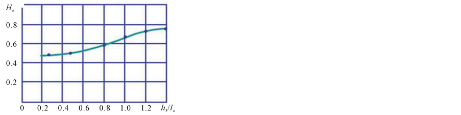
Figure 4. Arc efficiency vs. the ratio of the penetration depth in a metal and slag to the arc length.

Figure 5. High-power (EAFIC) with independent secondary phase windings: 1 - 21—see Figure 2 for coordinate designators; 22—three bottom electrodes; 23—three output leads of furnace transformer to bottom electrodes.
The method of steel melting in EAF using three vertical arcs penetrating into the liquid metal [15] and independently powered from three independent phase circuits was registered. An EAF installation diagram with arcs powering from three independent sources, which eliminates the horizontal arc currents and deflecting electromagnetic forces was given in figure 5 Such three-phase electric arc furnace with independent arc currents (EAFIC) (figure 5) differs from the conventional three-phase EACs in that the secondary windings of transformer form three independent single-phase arc power systems rather than being connected in a triangle through a bus bar bridge (or in a flexible cable based triangle, electrode based triangle, etc.). The entry ends of the transformer’s secondary phase windings a, b, c are connected with respective arcs of phases a, b, c through a short circuits whereas exit ends of the transformer’s secondary phase windings x, y, z are connected with respective hearth electrodes through a hearth current lead. Such circuit diagram of the three-phase transformer’s secondary winding connections with arcs is equivalent to powering of three arcs from three independent single-phase transformers.
In this scheme, the output current from a secondary winding’s entry end terminal of transformer, for example b, passes sequentially through a short circuit of phase b, arc, metal bath in vertical direction, hearth electrode of phase b, and finally exits through the hearth current lead of the phase b to the secondary winding’s exit terminal y of the transformer.
There are no two ways about b phase current. The other two-phase currents pass in a similar manner. Bottom electrodes may be made of lighting refractors or rod typed with steel top and water-cooled bottom.
Thus, current of each phase, passing through the metal bath holds its vertical direction; there are no conditions for deflecting electromagnetic force and it is absent in EAFIC. Axial force, acting on the liquid metal bath surface, persists and arc is submerged into the bath depression, its radiation to the interfurnace space, filled with a gas and on the water-cooled wall and roof panels, power loss decrease, arc efficiency increases.
We calculated analytically [8] , an average angular coefficients of arc radiation onto the metal bath and the arc efficiency in EAFIC.
The following assumptions were made for 100-t EAFIC: S = 80 MVA, U2l = 940 V, Ia = 50 kА, Ua = 520 V, la = 500 mm, θ = 0˚, hm = 150 mm, hsl = 0 - 400 mm, h3 = hsl +hm. The calculated results of arc efficiency are demonstrated in Table2
According to the calculated data (Table 2), we plotted a graph ηa = f(h3/Ia) in EAFIC (figure 6, curve 1). A similar dependence for EAF (curve 2) is given in Figure 6 for reference the arcs of EAF and EAFIC. It is shown that arc efficiency of 100-t EAFIC changes from 0.61 in the absence of a slag to 0.97 at a slag height of 400 mm. Arc efficiency may be of 0.97 in 100-t EAF only after well cutting by arcs of 2 - 2.5 m height and arc glowing onto liquid metal, surrounded by solid charge. During this period of 5 - 6 minutes 93% - 97% of arc power, all the arc column radiation incident on solid charge and absorbed by it. Arc efficiency decrease 5 - 6 minutes after well cutting, since wells expand, charge sinks, the part of arc radiation hits the roof and worked off charge upper wall panels and passed away as loss with cooling water and heat.
When arcs glow vertically at the liquid stage of melting in the depression of a slag and metal of height equal to or more than arc length, it is equivalent energetically to arc glowing in well of solid charge of 2 - 2.5 m height: 93% - 97% of arc heat power, arc column radiation are absorbed by the slag and the metal. Arc efficiency of 100-t EAFIC ~1.3 times higher than ac efficiency of 100-t EAF with slag absence and ~1.4 times higher at slag height of 350 mm.
Calculated results of arc efficiency of 120-t EAF depending on slag height are compared with experimental data of energy metering and slag height, obtained on operation 120-t EAFs [13] . Experimental data and measurement results are accordingly as follows: hsl = 356 mm, specific energy consumption q = 203 kWh of liquid steel, ηa = 0.67; hsl= 238 mm, q = 260 kWh, ηa = 0.52. Increase 1.5 times in slag height (from 238 to 356 mm)
Table 2. Arc efficiency vs slag height in 100-t EAFIC.
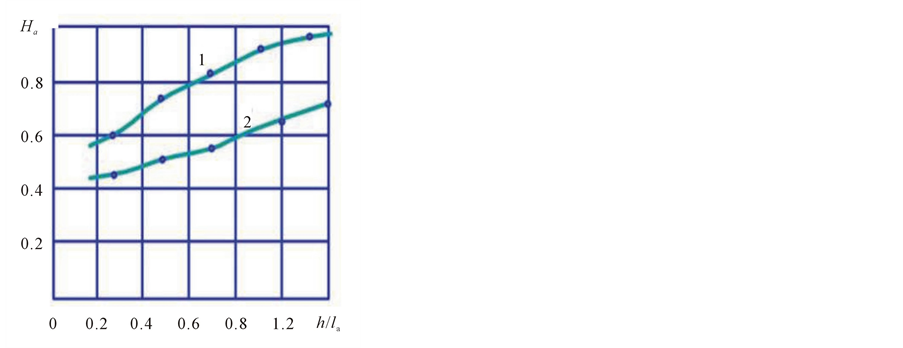
Figure 6. Arc efficiency vs. the ratio of the arc penetration depth in a metal and slag to the arc length in EAFIC (1) and a three-phase EAF (2).
leads to 1.29 decrease in specific energy consumption and 1.29 increase in arc efficiency i.e., there is an inverse relationship between specific energy consumption and arc efficiency: the more the arc efficiency the less the specific energy consumption and vice versa. Hence specific energy consumption may be 1.3 - 1.4 times less in 100-t EAFIC as compared with 100-t EAF.
3. Conclusion
In three-phase EAFs arcs are affected by two electromagnetic forces: axial and deflecting. Axial electromagnetic force exerts a positive influence on technical and economical indices of furnace operation, since arc is submerged into the slag and metal under its action, and an effective output absorbed by the metal increases. Deflecting electromagnetic force exerts a detrimental effect on technical and economical indices, since arc is thrown off depression in the metal and slag, its radiation on the walls and roof, gas, filled free space increase, an effective output absorbed by the metal decreases. In EAFIC deflecting electromagnetic force is eliminated and axial force is valid. We recognized analytically that in 100-t EAFIC at the stage of charge melting arc efficiency is 1.5 times higher than in conventional electric arc of the same capacity and specific energy consumption is 1.5 times less per melting.
References
- Nikol’skii, L.E., Smolyarenko, V.D. and Kuznetsov, L.N. (1981) Thermal Operation of Electric Arc Furnaces. Metallurgiya, Moscow.
- Makarov, A.N. and Sokolov, A.Yu. (2008) Effect of Inductive Reactance on the Technical and Economic Indices of Arc Steel Melting Furnaces. No. 11, Electrichestvo, Moscow, 65-68.
- Makarov, A.N. and Sokolov, A.Yu. (2009) Electric, Eometric, and Thermal Parameters of the Arcs Glowing in Metal-Vapors. No. 11, Elektrometallurgiya, Moscow, 19-24.
- Finkelnburg, W. and Maecker, H. (1956) Elektrische Bogen und Thermisches Plasma. Handbuch der Physik, 254-444.
- Makarov, A.N. and Svenchanskii, A.D. (1992) Optimum Thermal Conditions of Electric Arc Furnaces. Enegoatomisdat, Moscow.
- Makarov, A.N. (2003) Heat Exchange in Electric Arc and Flame Furnaces and Boiler Fire-Boxes. TGTU, Tver.
- Makarov, A.N. (2012) Regularity between Radiation Parameters of Isothermal Coaxial Cylinder Gas Layers Formed during Fuel Flare and Arc Glow in Metallic Vapors at Atmospheric Pressure. Collection of Scientific Papers, Ideas, Hypotheses, RANS Publishing, Moscow, 33-37.
- Makarov, A.N. (2012) Regularities, Accompying Glowing of Electric Arc and Torch in Metallurgy Furnaces. Geometric Physical and Analytical Model of an Arc and a Torch. No. 7, Elektrometallurgiya, Moscow, 22-32.
- Makarov, A.N. (2012) Regularities Accompying Glowing of Electric Arc and Torch in Metallurgy Furnaces. The Use of Scientific Discovery for Energy and Fuel Saving in Metallurgy Furnaces. No. 8, Elektrometallurgiya, Moscow, 28-35.
- Sisoyan, G.A. (1971) Electric Arc in Electric Furnace. Metallurgiya, Moscow.
- Spelitsyn, R.I. (1975) Penetration of an Electric Arc into the Liquid Bath in a High Power Electric Arc Furnace. No. 12, Elektrotermiya, Moscow, 10-11.
- Pashkis, V. (1945) Industrial Electric Furnaces and Appliance. New York.
- Kuznetsov, M.S., Yakushev, E.V., Kulagin, S.A., Kotelnikov, G.I., Semin, A.E., Kosyrev, K.L. and Kulish, R.S. (2010) Effect of Metal Charge and Slag Depth on Steelmaking Practice in Arc Furnace. No. 2, Elektrometallurgiya, Moscow, 2-6.
- Makarov, A.N., Sharova, Yu.A. and Galkin, V.Yu. (2008) A Three-Phase in Arc Steel-Melting Furnace. RF Patent 2333438.
- Makarov, A.N. and Sokolov, A.Yu. (2009) Method of Steel-Melting in a Three-Phase EAF. RF Patent 2368670.