Journal of Electronics Cooling and Thermal Control
Vol.06 No.02(2016), Article ID:67412,10 pages
10.4236/jectc.2016.62007
Efficient Cooling System Using Electrocaloric Effect
Shigeki Hirasawa*, Tsuyoshi Kawanami, Katsuaki Shirai
Department of Mechanical Engineering, Kobe University, Kobe, Japan
![]()
Copyright © 2016 by authors and Scientific Research Publishing Inc.
This work is licensed under the Creative Commons Attribution International License (CC BY).
http://creativecommons.org/licenses/by/4.0/


Received 12 May 2016; accepted 13 June 2016; published 16 June 2016
ABSTRACT
The electrocaloric effect in thin films of an electrocaloric material has the potential to be used for efficient cooling systems for high power electronic devices. We numerically calculated the effect of parameters in electrocaloric refrigeration with a thermal switch of fluid motion on the thermal performance. The system of changing air and water flow with the pulse generation of cold energy increased the heat transfer efficiency to 67% at a frequency of 5 Hz. The optimum time delay of water flow to increase the heat transfer efficiency was zero at low frequency and became half of the time period to change heat for a high frequency of 100 Hz. When the heat transfer efficiency was high, the final temperature change in water flow was not the maximum temperature change.
Keywords:
Electrocaloric Refrigeration, Thermal Switch, Optimization, Pulse Heating, Frequency

1. Introduction
The electrocaloric effect in thin films has the potential to be used for efficient refrigerators and cooling systems for high power electronic devices. Applying an electric field to an electrocaloric material raises its temperature, and decreasing the field lowers its temperature [1] . Figure 1 shows a model of a cooling system using the electrocaloric effect. A thin electrocaloric material was coupled with two thermal switches. The electrocaloric material alternatively generated heat energy and cold energy. Here, cold energy means negative heat energy. The heat energy was transferred to the hot side of the system, and the cold energy was transferred to the cold side separately. The coupling of multi-layers of thin films of an electrocaloric material with thermal switches can work as an efficient refrigerator. The cooling rate of the refrigerator can be easily increased using the electrocaloric effect by increasing the frequency of the electric field, so studies on the high-frequency behavior of the cooling system are important.

Figure 1. Model of cooling system using electrocaloric effect.
Some studies on electrocaloric refrigeration have been conducted. Epstein and Malloy [1] proposed an idea of a thin thermal-switching device using liquid crystals to develop an electrocaloric refrigerator that worked at a frequency of 1000 Hz, and the film thickness was 10 mm. Radebaugh et al. [2] reported the electrocaloric refrigeration for applications of cryogenics. They studied two types of thermal switches: a multiple-leaf contact switch and a magneto thermal switch. Jia et al. [3] used a mechanical thermal switch by moving it up and down with a frequency of 0.1 - 0.3 Hz. Sato [4] reported the experimental results of the thermal switching behavior of a heat pipe for a cooling device based on the electrocaloric effect. Sato used a multi-layer ceramic capacitor and reported that the temperature of the capacitor dropped 0.49 K at a frequency of 0.1 Hz. Guo et al. [5] reported on the fluid-based electrocaloric refrigeration system, in which a heat transfer fluid moved back and forth across the electrocaloric material. The size of the cooling element was 7 ´ 2.5 mm, which was a good size to cool electronic devices, and the film thickness of an electrocaloric material was 10 mm, and the frequency was 1 - 30 Hz. They studied the effect of the operating frequency and electric field amplitude, and reported the time lag between the electric field and the diaphragm motion significantly affected the cooling power. Ozbolt et al. [6] reviewed the technologies for the electrocaloric refrigeration. Hirasawa et al. [7] reported the thermal switching behavior of a flat heat pipe. They reported the maximum frequency of the thermal switching behavior of the flat heat pipe was 1 Hz. Most previous experimental studies were at low frequency less than 1 Hz. Some studies for high frequency neglected practical problems such as the effect of deformation of thin film of 10 mm thickness. For practical use of electrocaloric refrigeration to cool electronic devices, more studies are still needed to fully understand the potential for the electrocaloric refrigeration on the system level.
In this work, we studied the effect of parameters in electrocaloric refrigeration with a thermal switch of fluid motion on the thermal performance. We systematically studied the effects of changing air and water flow, time delay of water flow, water flow velocity, pulse heating and frequency. The optimization design guidelines to increase performance of the electrocaloric refrigeration with practical conditions were clarified.
2. Cooling System Using Electrocaloric Effect with Thermal Switch of Fluid Motion
The high-frequency behavior of the cooling system is important to enhance the cooling rate of the refrigerator using the electrocaloric effect. However, the material has a thermal time constant to change temperature according to the size.
Figure 2 shows the model of the cooling system using the electrocaloric effect with a thermal switch of fluid motion. The electrocaloric material is a flat thin film, and both sides of the film contact the hot water and cold water as they flow in thin-flow channels. Figure 3 shows the working diagram of the electrocaloric material and fluid motion. The electrocaloric material alternatively generates heat energy and cold energy with each time period te and frequency F = 1/(2te). When the electrocaloric material generates heat energy, water flows in the upper channel with a time delay td, and the heat energy is transferred to the hot side of the system. At that time, air is present in the lower channel. However, when the electrocaloric material generates cold energy, water flows in the lower channel with a time delay td and the cold energy is transferred to the cold side of the system. At that time, air is present in the upper channel. In this system, the fluid motion works as the thermal switch. The cold side of the system contacts high power electronic devices and the hot side is cooled by a forced convection of air with fins. In this work, we used water but we had the option to change the heat transfer fluid. As the amount of the fluid was very little, the MEMS devices enabled the fluid to move. The design of the cooling system struc-

Figure 2. Model of cooling system using electrocaloric effect with thermal switch of fluid motion.

Figure 3. Working diagram of electrocaloric material and fluid motion.
ture should be optimized for practical applications to cool electronic devices. In this work, we focused on optimizing the thermal performance.
Figure 4 shows the maximum thickness of the electrocaloric material be and water flow channel bw within the thermal time constant to change temperature. Calculation method of the maximum thickness is explained below. The order of time constant tc (s) of thermal conduction in a film was estimated by Equation (1) [8] .
![]() (1)
(1)
Here, r: density (5800 kg/m3 for electrocaloric material [4] and 1000 kg/m3 for water [8] ), c: specific heat (430 J/(kg×K) for electrocaloric material and 4200 J/(kg×K) for water), l: thermal conductivity (1 W/(m×K) for electrocaloric material and 0.62 W/(m×K) for water), and b: thickness of the film (m).
The frequency of the changing electric field F (Hz) should be determined within the order of the thermal time constant tc to keep good efficiency, and they have the following relationship.
![]() (2)
(2)
The maximum thickness of be and bw in Figure 4 was calculated from Equations (1) and (2).
The order of surface heat flux qe (W/m2) of the electrocaloric material was estimated by Equation (3) for the thickness be, the generating heat per unit volume Qg (J/m3) for each change in the electric field, and the frequency of changing the electric field F without heat loss.
![]() (3)
(3)
We assumed that the heat generation rate was constant as the electric field was supplied, as shown in Figure 3. Representative values of the heat change per unit volume for each change in the electric field were reported to be Qg = 4 ´ 107 J/m3 for a change in the electric field of 1.5 ´ 108 V/m [9] . Figure 4 also shows the order of the maximum surface heat flux qe calculated with Equation (3).
![]()
Figure 4. Maximum surface heat flux, thicknesses of electrocaloric material and water flow channel.
When the thermal switch was made by fluid motion in a thin-flow channel, the order of pressure drop DP of the fluid caused by the inertia and viscosity was estimated by Equation (4) [8] .
![]() (4)
(4)
Here, u: flow velocity, t: time, x:coordinate to flow direction, y:coordinate to thickness, r: density, m: viscosity, tc: moving time, bw: thickness of flow channel, and xe: length of flow channel.
Figure 5 shows the order of the pressure drop DP for the water calculated with Equation (4). The thickness of flow channel bw was obtained from Figure 4, the moving time tc was obtained from Equation (2), and the length of the flow channel was assumed to be xe = 0.1 m. In a practical condition the pressure drop DP should be less than the order of 105 Pa. Then, the maximum frequency became on the order of F = 50 Hz from Figure 5. The thicknesses of the electrocaloric material and water flow channel became on the order of be = 0.08 mm and bw = 0.05 mm from Figure 4. Also, the heat flux of the surface of the electrocaloric material became on the order of qe = 2 ´ 105 W/m2.
In this work, we studied the case of F = 5 Hz, the time period to generate heat was te = 0.1 s, the thickness of the electrocaloric material be = 0.2 mm, the thickness of water flow channel bw = 0.1 mm, the heat flux of the surface of electrocaloric material qe = 4 ´ 103 W/m2 as the standard condition, which was substantially smaller than the maximum values shown in Figure 4. In this work, the water flow velocity is shown with the ratio between the flow time tw to pass the width of the electrocaloric material and the time period to change heat te. The standard condition of the flow velocity was assumed to be the condition of tw = 0.1 te. Then, the maximum temperature change in the water was 0.25˚C for each layer of thin film of the electrocaloric material for the standard condition. The temperature change was increased using multi-layers of the electrocaloric material films in practice. Heat transfer efficiency h was defined as the ratio between the heat transfer rate to the cold side of system and the generated cold energy in the electrocaloric material.
The energy equation of the hot water and cold water flow is as follows [8] .
![]() (5)
(5)
Here, Tw: water temperature, u: flow velocity (m/s), Qw: heat transfer rate per unit volume of water (W/m3), rw: density, cw: specific heat, and lw: thermal conductivity of water.
The energy equation of the electrocaloric material is as follows [8] .
![]() (6)
(6)
![]()
Figure 5. Pressure drop of water flow.
Here, Te: temperature of electrocaloric material, Qe: generating heat per unit volume by the electrocaloric effect (W/m3), be: thickness of electrocaloric material, and bw: thickness of water flow channel.
The heat transfer rate per unit volume of water Qw and the laminar heat transfer coefficient a (W/m2×K) from the surface of the electrocaloric material to the water in the thin-flow channel were calculated with the following equations [8] .
![]() (7)
(7)
![]() (8)
(8)
Here, Tek: the surface temperature of the electrocaloric material in the flow channel.
We numerically calculated these equations using the finite difference method [8] . The number of calculation meshes was 10 to the flow direction x, and 5 to the thickness direction y (they are Th, Tek−h, Te, Tek−c, and Tc). The calculation time step was 1/10 of the heat generating time te.
3. Calculation Results of Effect of Parameters on Thermal Performance
3.1. Effect of Changing Air and Water Flow
Figure 6(a) shows the temperature changes in the hot water Th, cold water Tc, and electrocaloric material Te at the exit side for the standard case of changing air and water flow as shown in Figure 3. In addition, Figure 6(b) shows the temperature changes for the case of changing only the water flow velocity without air. Which means that the hot water flowed in the upper channel during the time heat energy was generated in the electrocaloric material, and the water existed at rest in the upper channel when cold energy was generated. The cold water flowed in the lower channel during the time cold energy was generated, and the water existed at rest in the lower channel when heat energy was generated. The calculation conditions were the frequency F = 5 Hz, the time period to change heat te = 0.1 s, and the time delay td = 0. The flow velocity was the condition of time tw to pass the width of the electrocaloric material to make tw = 0.1te, and the generating heat energy flux and cold energy flux on the electrocaloric material were qe = +4 ´ 103 and −4 ´ 103 W/m2. The temperature of the cold water in Figure 6(b) was higher than that in Figure 6(a) because the cold water existed at rest in the lower channel when heat energy was generated. Table 1 shows the heat transfer efficiency h, the maximum temperature change in the cold water DTmax, and the final temperature change in the cold water DTfin. We found the system of changing air and water flow increased the heat transfer efficiency to 19%, about four times higher than that of the case of changing flow velocity without air. Therefore, the system of changing air and water flow was preferable. The maximum temperature change occurred in the final stage, and DTmax = DTfin in Table 1.

 (a) (b)
Figure 6. Effect of changing air and water flow on temperature change. (a) Changing air and water flow; (b) Changing only water flow velocity without air.

Table 1. Heat transfer efficiency and temperature change.
3.2. Effect of Time Delay of Water Flow
In Figure 6(a), the temperature of the cold water Tc was a positive value at the time 0.10 - 0.13 s, which means the cold water was heated initially by the residual heat of generated heat energy caused by the heat capacity of the electrocaloric material. Then, we calculated the value by changing the time delay of the water flow from the change in the time heating was applied in the electrocaloric material. Figure 7 shows the effect of the delay time td on the heat transfer efficiencyh, maximum temperature change in the cold water DTmax, and final temperature change in the cold water DTfin. The calculation conditions were the frequency F = 5 Hz, the time period to change heat te = 0.1 s, and the flow time to pass the width of the electrocaloric material tw = 0.1te. The heat transfer efficiencies h were highest at the delay time td = 0.03 s. When the delay time td was less than 0.03 s, the cold water was heated initially by the residual heat of the electrocaloric material as shown in Figure 6(a). When the delay time td was longer than 0.03 s, the heat transfer time between the cold water and the cold electrocaloric material decreased. As the delay time td increased, the final temperature change DTfin decreased from the maximum temperature change in the cold water DTmax. Figure 8 shows the temperature changes in the hot water Th, the cold water Tc, and the electrocaloric material Te at the exit side for td = 0.03 s. All the temperatures of the cold water Tc were negative values.
3.3. Effect of Water Flow Velocity
Figure 9 shows the effect of the water flow velocity on the heat transfer efficiencyh, the maximum temperature change in the cold water DTmax, and the final temperature change in the cold water DTfin. The water flow velocity was shown with the ratio between the flow time tw to pass the width of the electrocaloric material and the time period to change heat te. The calculation conditions were the frequency F = 5 Hz, the time period to change heat te = 0.1 s, and the time delay td = 0.03 s. When the time to pass the width of the electrocaloric material tw was less than10% of the time period to change heat te (tw < 0.1te), the heat transfer efficiencies h were high because almost all the cold water reached the cold side of the system for high velocity of water flow. The maximum temperature change in the cold water DTmax decreased for a high velocity of water flow because the flow volume of water increased. Figure 10 shows the temperature changes in the hot water Th, the cold water Tc, and the electrocaloric material Te at the exit side for the case of the slow velocity of water flow at (tw/te) = 1.

Figure 7. Effect of time delay of water flow on heat transfer efficiency and temperature change.

Figure 8. Temperature change for time delay td = 0.03 s.

Figure 9. Effect of water flow velocity on heat transfer efficiency and temperature change.
3.4. Effect of Condition of Generating Heat Energy and Cold Energy
In Figure 6(a), the heating rate was constant when the heat energy and cold energy were generated. Figure 11 shows the temperature changes in the hot water Th, cold water Tc, and electrocaloric material Te at the exit side
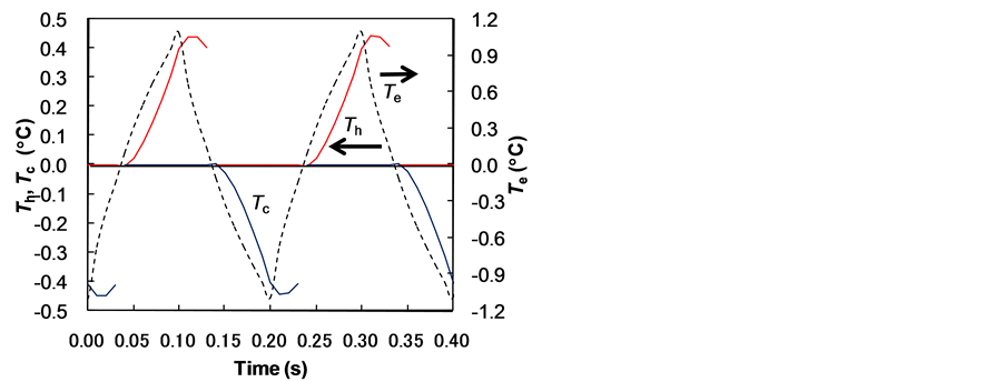
Figure 10. Temperature change for slow velocity of water flow (tw/te) = 1.
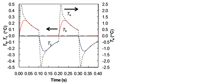
Figure 11. Temperature change for pulse heating.
Table 2. Heat transfer efficiency and temperature change.
for the case of pulse heating, which means all the energy generated at the initial time period to change the generation of heat energy and cold energy. The calculation conditions were the frequency F = 5 Hz, the time delay td = 0, and the flow time to pass the width of the electrocaloric material tw = 0.1te. The generation of the heat energy flux and cold energy flux on the electrocaloric material were qe = +4 ´ 104 and −4 ´ 104 W/m2 at the initial period 0.01 s of the time period to change the generation of the heat energy and cold energy te = 0.1 s. Table 2 shows the heat transfer efficiency h, maximum temperature change in the cold water DTmax, and final temperature change in the cold water DTfin. We found the system of pulse heating increased the heat transfer efficiency to 67 %, which was about 3.5 times higher than that of the case of constant heating. Therefore, the system of pulse heating was preferable.
Figure 12(a) shows the effect of the frequency F on the heat transfer efficiency h, maximum temperature change in the cold water DTmax, and final temperature change in the cold water DTfin. The time period to change heat was te= 1/(2F), the flow time to pass the width of the electrocaloric material was tw = 0.1te, the delay time td

 (a) (b)
Figure 12. Effect of frequency. (a) Efficiency and temperature change; (b) Optimum time delay.
was optimized to maximize the heat transfer efficiency at each condition, and the generating heat energy and cold energy on the electrocaloric material chosen to be the maximum temperature change in the water became 0.25˚C. As the frequency F increased, the heat transfer efficiencies h decreased, and the maximum temperature change in the cold water DTmax decreased. The cooling rate of the refrigerator can be increases by increasing the frequency of the electric field, but the heat transfer efficiencies decreases at high frequency for constant thicknesses of the electrocaloric material and water flow channel. Figure 12(b) shows the effect of the frequency F on the optimum delay time td to maximize the heat transfer efficiency. The optimum delay time td was zero (td= 0) at low frequency and became half of the time period to change heat te (td = 0.5te) for the case of high frequency 100 Hz.
4. Conclusions
We numerically calculated the effect of parameters in electrocaloric refrigeration with a thermal switch of fluid motion on the thermal performance. The following results were obtained.
1. The design guidelines to increase performance of the electrocaloric refrigeration with a thermal switch of fluid motion were clarified. For the thermal switch of fluid motion with a practical condition of the pressure drop of fluid flow, the maximum frequency was on the order of F = 50 Hz, and the thicknesses of the electrocaloric material and water flow channel were on the order of be = 0.08 mm and bw = 0.05 mm, and the heat flux of the surface of the electrocaloric material was on the order of qe = 2 × 10⁵ W/m2.
2. The optimization guidelines of the electrocaloric refrigeration system were clarified. The system of changing air and water flow according to the generation of heat energy and cold energy in the electrocaloric material increased the heat transfer efficiency to about 4 times higher than that of the case of changing the flow velocity without air. The system of pulse heating increased the heat transfer efficiency to 67%, about 3.5 times higher than that of the case of constant heating at the frequency of 5 Hz. When the water flow velocity was high and the flow time to pass the width of the electrocaloric material tw was less than 10% of the time period to change heat te (tw < 0.1te), the heat transfer efficiencies h were high.
3. The optimum time delay of water flow to increase the heat transfer efficiency was 0.03 s when the frequency of generating heat energy and cold energy of the electrocaloric material was 5 Hz. The optimum delay time td was zero (td = 0) at low frequency and became half of the time period to change heat te (td = 0.5te) for a high frequency of 100 Hz. When the heat transfer efficiency was high, the final temperature change in water flow DTfin was not the maximum temperature change DTmax.
Acknowledgements
Authors thank to Mr. Makoto Endo, Mr. Naoki Fujimoto, Mr. Yusuke Satake, and Mr. Katsuhisa Hayashi of Kobe University for helping analysis and experiment.
Cite this paper
Shigeki Hirasawa,Tsuyoshi Kawanami,Katsuaki Shirai, (2016) Efficient Cooling System Using Electrocaloric Effect. Journal of Electronics Cooling and Thermal Control,06,78-87. doi: 10.4236/jectc.2016.62007
References
- 1. Epstein, R.I. and Malloy, K.J. (2009) Electrocaloric Devices Based on Thin-Film Heat Switches. Journal of Applied Physics, 106, Article ID: 064509.
http://dx.doi.org/10.1063/1.3190559 - 2. Radebaugh, R., Lawless, W.N., Siegwarth, J.D. and Morrow, A.J. (1979) Feasibility of Electrocaloric Refrigeration for the 4-15 K Temperature Range. Cryogenics, 19, 187-208.
- 3. Jia, Y. and Ju, Y.S. (2012) A Solid-State Refrigerator Based on the Electrocaloric Effect. Applied Physics Letters, 100, Article ID: 242901.
http://dx.doi.org/10.1063/1.4729038 - 4. Sato, W. (2013) A Study of a New Cooling Device Based on the Electrocaloric Effect. Proceedings of ASME 2013 International Mechanical Engineering Congress, San Diego, 15-21 November 2013, IMECE2013-62258.
- 5. Guo, D., Gao, J.B., Yu, Y.J., Santhanam, S., Slippey, A., Fedder, G.K., McGaughey, A.J.H. and Yao, S.C. (2014) Design and Modeling of a Fluid-Based Micro-Scale Electrocaloric Refrigeration System. International Journal of Heat and Mass Transfer, 72, 559-564.
http://dx.doi.org/10.1016/j.ijheatmasstransfer.2014.01.043 - 6. Ozbolt, M., Kitanovski, A., Tusek, J. and Poredos, A. (2014) Electrocaloric Refrigeration: Thermodynamics, State of the Art and Future Perspectives. International Journal of Refrigeration, 40, 174-188.
http://dx.doi.org/10.1016/j.ijrefrig.2013.11.007 - 7. Hirasawa, S., Nakamu, T., Kawanami, T. and Shirai, K. (2015) Study on Unsteady Thermal-Switching Function of Flat Heat Pipe. Proceedings of the ASME 2015 International Mechanical Engineering Congress & Exposition, Houston, 13-19 November 2015, IMECE2015-50158.
- 8. Holman, J.P. (2002) Heat Transfer. 9th Edition, McGraw-Hill International Book Company, Boston.
- 9. Zhang, G., Li, Q., Gu, H., Jiang, S., Han, K.R., Gadinski, M.R., Haque, M.A., Zhang, Q., and Wang, Q. (2015) Ferroelectric Polymer Nanocomposites for Room-Temperature Electrocaloric Refrigeration. Advance Material, 27, 1450-1454.
http://dx.doi.org/10.1002/adma.201404591
NOTES

*Corresponding author.