T. K. HASSAN
77
of 1(peak). der to valie repeon-
troller performance foinput voltagariation, u-
lated steady state eforms of inductor currLnd
fee current or the case nput voith
70 V In ordate thtitive c
r
wav
e vthe sim
ent i a
re renciref fof iltage w
20% larger than the nominal value and Rl = 450 Ω (out-
put power equals 200 W) are plotted in Figure 13. The
reference current and inductor current are coincident and
good tracking is also maintained and is not affected with
the variation of input voltage.
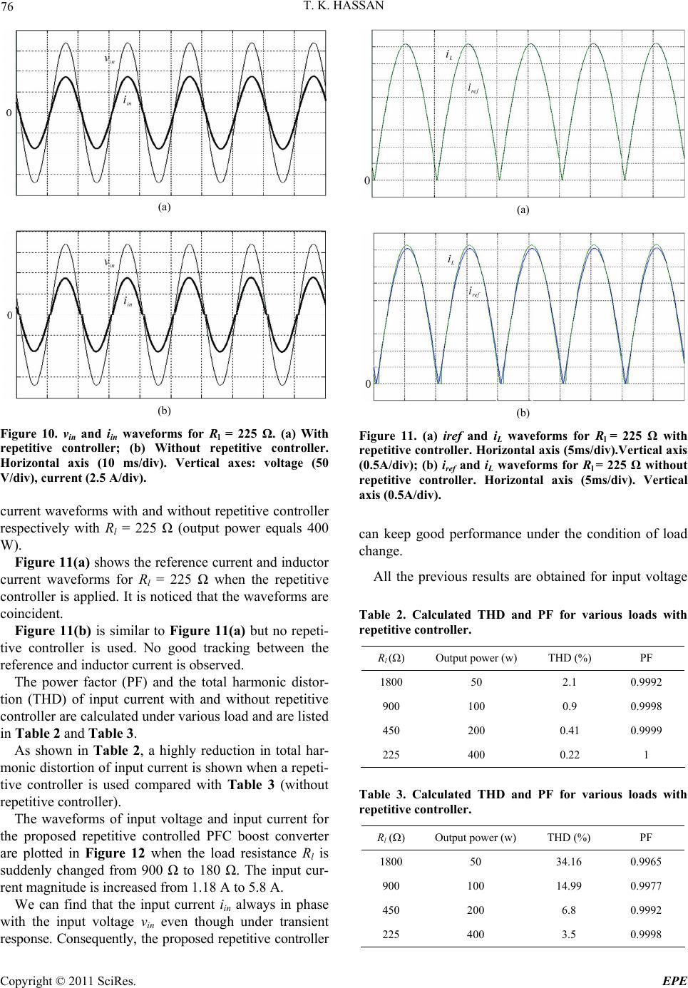
Figure 14 shows the input voltage and input current
Figure 12. vin and iin waveforms with repetitive controller.
Rl is changed from 450 Ω to 180 Ω. Horizontal axis (50
ms/div).Vertical axes: voltage (50 V/div), current (5 A/div).
Figure 13. iref and iL waveforms for Rl = 450 Ω without re-
petitive controller. Horizontal axis (5 ms/div). Vertical axis
(0.2 A/div). Amplitude of input voltage equals 203 V.
Figure 14. vin and iin waveforms for Rl = 450 Ω. with repeti-
tive controller. Horizontal axis (5 ms/div). Vertical ax
voltage (50 V/div), current (5 A/div). Amplitude of input
voltage equals 203 V.
waveforms for the same conditions in Figure 13. No
zero crossing distortion in input current is observed and
the input current is in phase with the input voltage.
5. Conclusions
In this paper, the control approach to solve the problem
of zero crossing distortion of input current of PFC boost
converter has been presented. To achieve this goal, a
repetitive controller is inserted in series with the PI con
y. Because our approach is based on
bility
ndwidth is included. Several simula-
to verify the validity of the proposed
es:
-
troller of current loop. We presented a graphical design
technique based on the frequency domain analysis of
linear system to achieve a repetitive controller that pre-
serves system stabilit
graphical inspection of the Nyquist envelop, the design
procedure was simple and intuitive. A low pass filter
with gain lower than one to ensure the system sta
and to limit the ba
tions are performed
repetitive controller. The results obtained with and with-
out repetitive controller are compared. The results with
repetitive controller shows very low total harmonic dis-
tortion of input current, good tracking of reference cur-
rent and inductor current (very low steady state error)
and no zero crossing distortion of input current. Transit
responses to step change in load are presented to exhibit
the robustness of the proposed repetitive controller
against load variations. The performance of the system
with the proposed controller has not affected with the
variation of input voltage.
6. References
[1] J. Sun, “On the Zero-Crossing Distortion in Single-Phase
PFC Converters,” IEEE Transactions on Power Elec-
tronics, Vol. 19, No. 3, 2004, pp. 685-692.
doi:10.1109/TPEL.2004.826491
[2] H. C. Chen, “Duty Phase Control for single-Phase Boost-
Type SMR,” IEEE Transactions on Power Electronics,
Vol. 23, No. 4, 2008, pp. 1927-1934.
doi:10.1109/TPEL.2008.924627
[3] M. Chen and J. Sun, “Feedforward Current Control of
Boost Single-Phase PFC Converters,” IEEE Transactions
on Power Electronics, Vol. 21, No. 2, 2006, pp. 338-345.
doi:10.1109/TPEL.2005.869746
. H. Li and C. M. Liaw, “Switch-Mode
Digital Robust Ripple Compensation and
Current Waveform Controls,” IEEE Transactions on
[4] H. C. Chen, S
Rectifier with
Power Electronics, Vol. 19, No. 2, 2004, pp. 560-566.
doi:10.1109/TPEL.2003.823200
[5] S. Hara, Y. Yamamoto, T. Omata and M. Nak
petitive Control System: A New
ano, “Re-
Type Servo System for
Periodic Exogenous Signals,” IEEE Transaction on
Automatic Control, Vol. 33, No. 7, 1988, pp. 659-668.
doi:10.1109/9.1274
Copyright © 2011 SciRes. EPE