Journal of Electromagnetic Analysis and Applications
Vol. 1 No. 1 (2009) , Article ID: 191 , 9 pages DOI:10.4236/jemaa.2009.11004
Impact of Reactive Power in Power Evacuation from Wind Turbines
1School of Electrical Sciences, Vellore Institute of Technology, Vellore, India-632014, 2 Christian College of Engineering and Technology, Ottanchatiram, Dindugal District. India-632014, 3Vellore Institute of Technology University, Vellore, India-632014.
Email: asran@vestas.com; spk25in@yahoo.co.in; ahuja.ankur.1986@gmail.com; kpalanisamy79@yahoo.co.in; jacobraglend@rediffmail. com; dpk0710@yahoo.com; vc@vit.ac.in
Received January 31st, 2009; revised February 17th, 2009; accepted February 28th, 2009.
Keywords: Distributed Generation (DG), Grid, Wind Turbines, Induction Generator, Islanding, Power Evacuation, Point of Common Connection 3 Phase to Ground Fault
ABSTRACT
Application of Distributed Generation (DG) to supply the demands of a diverse customer base plays a vital role in the renewable energy environment. Various DG technologies are being integrated into power systems to provide alternatives to energy sources and to improve reliability of the system. Power Evacuation from these remotely located DG’s remains a major concern for the power utilities these days. The main cause of concern regarding evacuation is consumption of reactive power for excitation by Induction Generators (IG) used in wind power production which affects the power system in variety of ways. This paper deals with the issues related to reactive power consumption by Induction generators during power evacuation. Induction generator based wind turbine model using MATLAB/SIMULINK is simulated and its impact on the grid is observed. The simulated results are analyzed and validated with the real time results for the system considered. A wind farm is also modeled and simulations are carried out to study the various impacts it has on the grid & nearby wind turbines during Islanding and system event especially on 3-Phase to ground fault.
1. Introduction
Wind is one of the most important resources found in nature’s bounty totally free of cost and without any hazardous effects. Perhaps that is why, in this hour of energy crisis,the entire human race has diverted its attention to wind energy as a suitable alternative to the conventional sources of energy we have been using for more than a century.
Having an insight into the statistics concerning installed wind power capacity,we see that the total capacity as of today is 93,849MW (2008). India stands fourth in wind power commissioning with an installed capacity of 7844.5MW (2008). But Germany with a capacity of 22,247MW (2008) shows that the distance to be covered is still huge. Of course, it instills a hope that the future will be bright with no reliance on conventional sources of energy and wind energy forming a large chunk of the installed capacity.
There are two types of utility-scale wind turbines, fixedand variable-speed. Fixed-speed wind turbines operate at a near constant rotor speed at all times and are directly connected to the power grid [1]. Fixed speed wind turbine which is used here for analysis operates within a very small range (around 5% of the nominal value) and in general they use a fixed shunt capacitor to provide reactive power compensation [2].
1.1 Islanding
A phenomenon which generally occurs in a network with Wind Generation in which a portion of the distribution network becomes Electrically Isolated from utility grid due to transmission system events & after disconnection, wind generator maintains supply to local loads. Islanding can be categorized as Intentional Island and Unintentional Island. Islanding is a condition in which local Distribution Generation systems continue to supply stable real power and reactive power to the local loads at a sustained voltage and frequency while the main Energy system is de-energized. An islanding condition creates a safety hazard and may cause damage to power generation and power supply facilities as a result of unsynchronized re-closure [3]. In general, after loss of the main source, the DG has to take charge of the remaining network and the connected loads; therefore, the loading condition of the DG is suddenly changed after islanding. Since the distribution networks generally include single-phase loads, it will be highly possible that the islanding changes the load balance of DG [4].
1.2 Intentional Island
Planned islanding is often called Intentional Islanding. This condition arises when a portion of the network is separated from the rest of the network for the sake of system reliability & maintaining the safety of the network. Utility personnel monitor the islanded system continuously & it poses no problem for the utility.
During the occurrence of a system outage, when several groups of generators can go out of-step with each other, it may be desirable to have selected islands where there is a minimal mismatch between load and generation. Switching operations carried out to split the system into such self-sufficient regions is called intentional islanding.
1.3 Unintentional Island
Sudden and unpredicted islanding is termed as unintentional islanding which mainly results due to the failure of anti-islanding techniques resulting in electrical isolation of an energized portion [5]. The energized portion will continue to supply power to the loads present in the island affecting the safety concerns for the utility personnel.
A section of the grid having balanced load and generation may become isolated from the rest of the grid by a sudden opening of a switch or a circuit breaker that causes the disconnection of the feeder from the grid. A common form of disconnection would typically arise from a momentary ground fault on the feeder, which is detected by the feeder ground relay and results in tripping of the feeder circuit breaker. Such an event is described in Figure 1. The single line to ground fault shown in the Figure1 is assumed to be transient in nature [6]. This fault could cause operation of utility breaker shown as a disconnection point suggested by the given Figure 1.
However, the transient fault may be undetectable by the DG and cause to exist after opening of the utility breaker. In this scenario, an unintentional island is formed after opening of the utility breaker. After disconnection from the grid, this island may be initially deficient in active and reactive power. The deficiency of active power is balanced by the release of kinetic energy from the rotating machinery connected to the system, and hence reduction in system frequency [6]. The deficiency of reactive power is mainly balanced by the export of reactive power from the embedded synchronous generator .An islanding event, such as described in this section, can be conveniently illustrated by a frequency and voltage versus time graph of Figure 2.
1.4 Implications of Inadvertent Islanding
Inadvertent islanding presents a number of safety, commercial, power quality, and system integrity problems [7]. In summary, the major issues are:
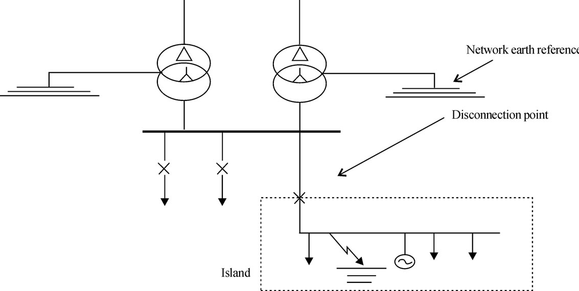
Figure 1. Ground fault disconnection
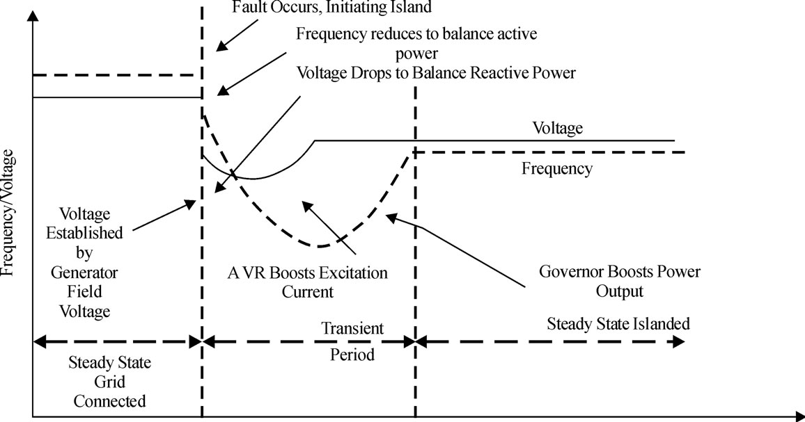
Figure 2. Voltage and frequency response
1) Line worker safety can be threatened by DG sources feeding a system after primary sources have been opened and tagged out.
2) Public safety can be compromised as the utility does not have the capability of de-energizing downed lines.
3) The voltage and frequency provided to other customers connected to the island are out of the utility’s control, yet the utility remains responsible to those customers.
4) Protection systems on the island are likely to be uncoordinated, due to the drastic change in short circuit current availability.
5) The islanded system may be inadequately grounded by the DG interconnection.
6) Utility breakers or circuit reclosers are likely to reconnect the island to the greater utility system when out of phase.
2. System Configuration
The parameters used for the simulation of the above model of an Induction Generator based wind turbine are as follows:
2.1 Induction Generator
A 3-phase squirrel cage induction generator with a nominal power of 843KVA, 690V (φ-φ), 50 HZ is used for the above system with the parameters shown in Table 1.
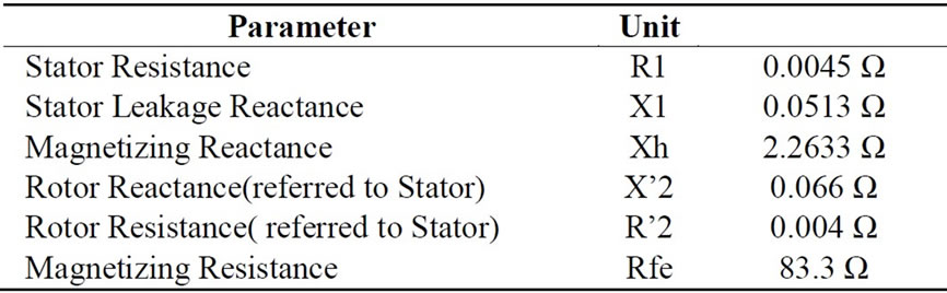
Table 1. Induction generator parameters
2.2 Three Phase Transformer
A Yg/ ∆ (D1) configuration of three phase (2-winding) transformer is used with a nominal power of 1MVA with following primary/Secondary Windings given in Table 2. Parameters used for the simulation of three phase PI section Line was given in Table 3.
2.3 Grid
A three-phase source with internal R-L impedance is used to implement a grid which is connected to the wind Generator through a T-Line & Transformer. The three phase Short-circuit Level at base voltage of 33KV is 25MVA with X/R ratio of 10.
2.4 Load
A 3-Phase resistive load of 675KW is used which is connected at the terminals of wind turbine. Simple wind farm based on fixed speed wind turbines is connected to a grid through a T-Line at Point of Common Connection (PCC).
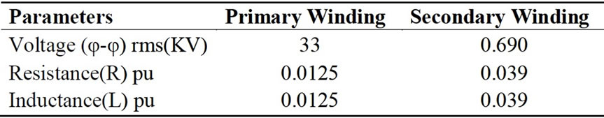
Table 2. WG transformer parameters
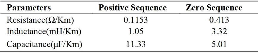
Table 3 Parameters for PI section transmission line
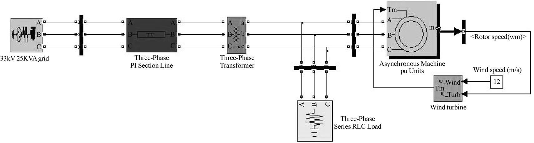
Figure 3. System configuration in SIMULINK
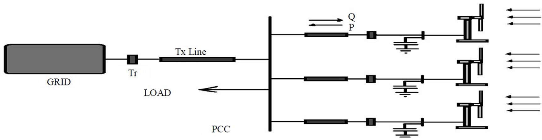
Figure 4. Outline of grid connected wind farm
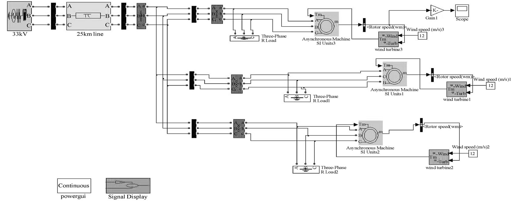
Figure 5. Wind farm connected to grid using SIMULINK
The second module of the paper deals with the Implementation of a Wind Farm & its Impact on Grid during Islanding which can be categorized as:
1) Wind Farm Configuration in SIMULINK.
2) Impact on Grid during Disconnection of a Wind Generator.
2.5 Wind Farm Configuration
A Wind Farm with three Identical Wind Turbines connected together to form a Wind farm of capacity 2.25MW is shown in the Figure 5.
In implementing a wind farm connected to a grid through a PCC needs a separate step-up Transformer at the PCC which is finally connected to the grid via Pi section T-Line. The difference between a single wind Turbine connected to a grid & a wind farm connected to grid can be seen by an additional Transformer’s & Individual short transmission lines connecting each Generator to PCC with their parameters mentioned below.
2.6 Transformer
With nominal power 10MVA a 33/66KV transformer with same parameters specified before.
2.7 T-Line
Short transmission lines connecting Individual Wind generators are of length 1 Km each with same parameters specified before.
The Islanding of a Wind turbine model is shown in Figure 6 using SIMULINK. The Impact of Disconnection of one of WG from the rest of the network is implemented here by Inserting a 3-phase breaker in series with the same WG & PCC in which switching of all the three phases from closed to open condition takes place after 1.5 Sec of operation of WG.
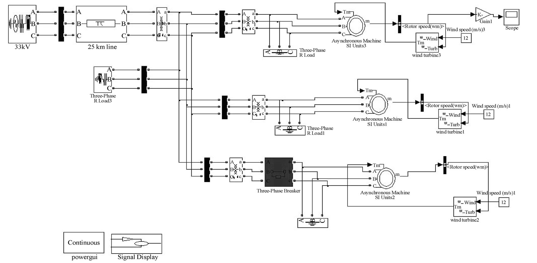
Figure 6. Islanding of a simulated wind turbine model
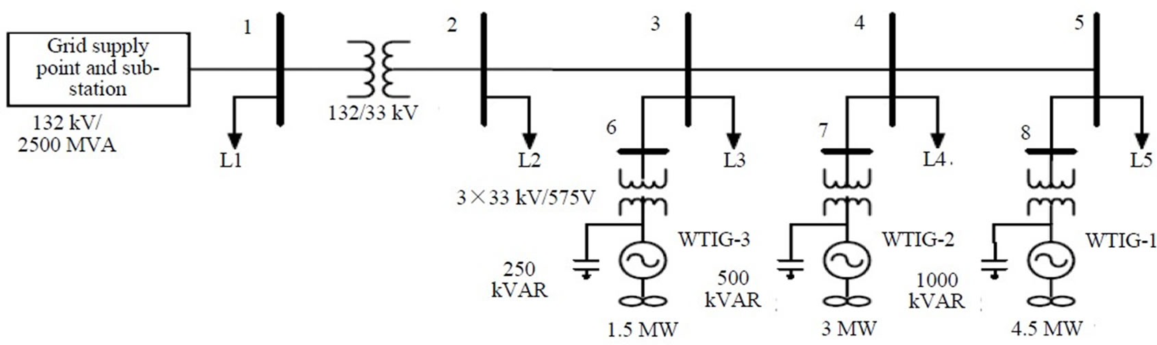
Figure 7. Network layout used for simulation [8]
The parameters for the Breaker are Transition Time: 1.5 Sec, Breaker Resistance: 0.001 Ω, Snubber Resistance: 0.000001 Ω, Snubber Capacitance: ∞.
Figure 7 is implemented in SIMULINK to Simulate Unintentional Islanding Condition.
2.8 Induction Generator
A 3-phase squirrel cage induction generator with a nominal power of 1.66MVA, 575V (φ-φ), 60 HZ is used for the above system with the parameters shown in Table 4.
A grounding Transformer is used to create a grounding point at the secondary side (∆) of grid 47MVA transformer with Xo=4.7 Ω [8].
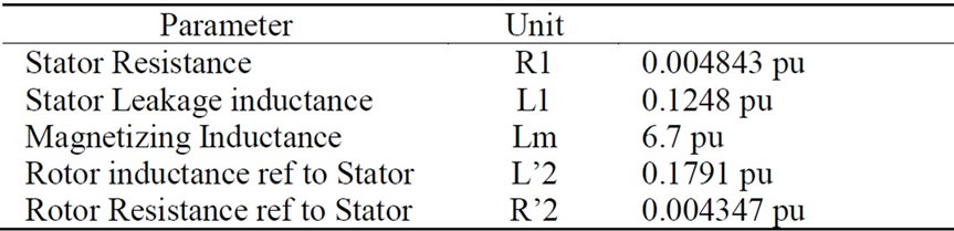
Table 4. Parameters for induction generator [8]
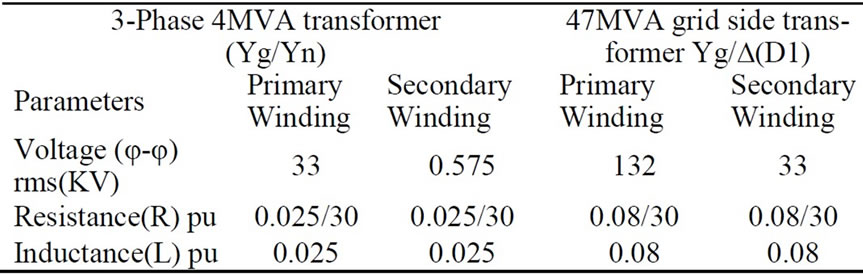
Table 5. Three phase transformer parameters [8]

Figure 8. Simulated model for unwanted islanding
2.9 Grid
A three-phase ideal voltage source along with a 3-phase mutual inductance block is used a grid with a capacity of 2500MVA&Xo/X1=3 [8].
3. Case Studies and Results
3.1 Normal Condition without any Compensation
For a Wind Farm of 2.25 MW under normal working condition, following results were obtained.
The waveform of P & Q at the Wind Generator terminals is shown in Figure 9. The waveform of P & Q at the Grid terminals are shown in Figure 10.The waveform of V, I, P & Q at the load terminals are shown in Figure 11.The loading conditions without any reactive power compensation are Load= (750+360j)*3, C1=C2=C3=0.
It is found that the requirement of reactive power by Induction generators without compensation is fulfilled by the grid which results in large deviation from the standard voltage values.
3.2 Islanding Condition
Following results were obtained under Islanding condition. The waveform of P & Q at the Wind Generator terminals are shown in Figure 12.The Frequency Response at the Wind Generator Terminal is shown in Figure 13.The waveform of V, I, P & Q at the Grid terminal are shown in Figure 14.The waveform of V, I, P & Q at the Load terminal are shown in Figure 15.
3.3 Unintentional Islanding Condition
Following results were obtained under Unintentional Islanding condition where Islanding can be detected by conventional method.
For PG=1.5MW, QG=-750 KVAR, PL=1.2MW, QL=20 KVAR, QC=250KVAR.
The waveform of V, I, P & Q at islanded Wind Generator terminals are shown in Figure 16.
Table No. 6 shows the simulated results of the Voltage at Generator Terminal for the clearing time. And Table 7 shows the IEEE Standards for Interconnection system response to abnormal voltages.
From the waveform as df/dt=1.19 HZ/Sec, ∆f =2.38HZ, f’ = f-∆f = 57.62Hz.
It is found that Islanding can be detected by the Conventional methods based on local parameters. Thereafter Islanding can be prevented in accordance with IEEE 1547 standards.

Table 6. Voltages at WG terminal (PL=1.2MW)
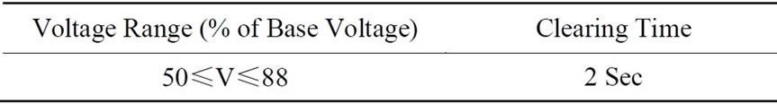
Table 7. IEEE 1547 standard (for voltage)
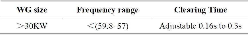
Table 8. IEEE 1547 standard (for frequency)
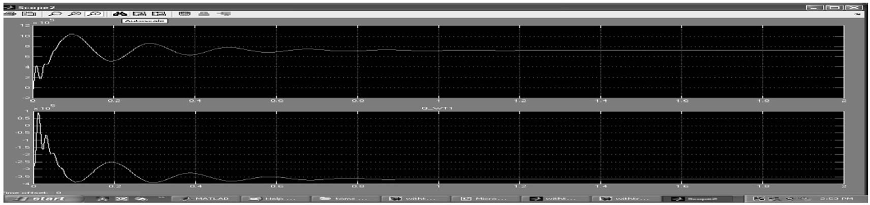
Figure 9. P & Q waveform at WG terminals
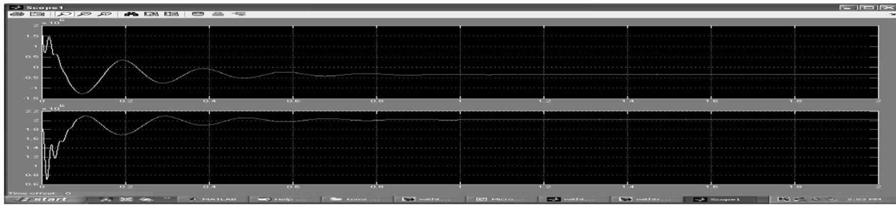
Figure 10. P & Q waveform at grid terminals
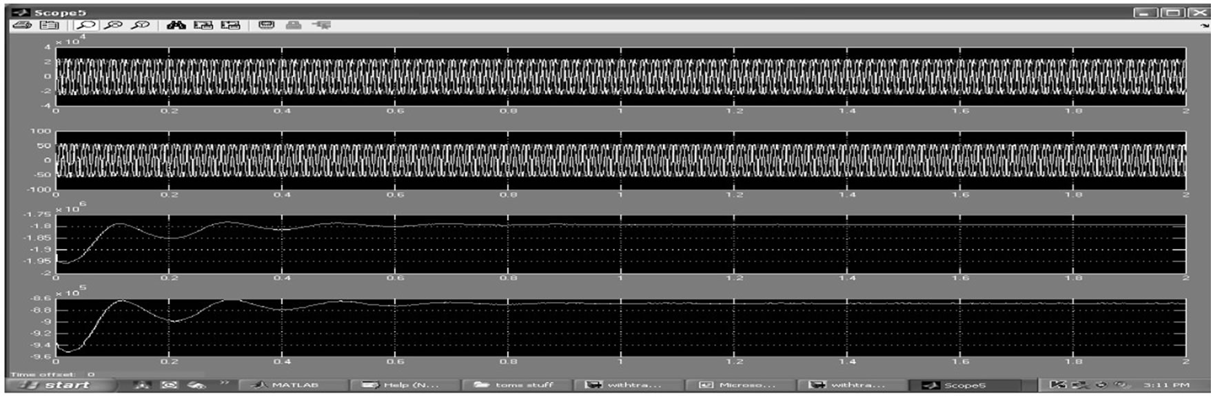
Figure 11. V, I, P & Q waveform at load end
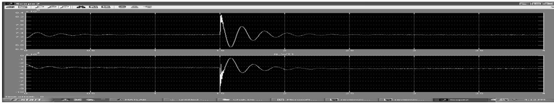
Figure 12. P & Q waveform at WG terminal during disconnection of one WG

Figure 13. Frequency response at WG terminal
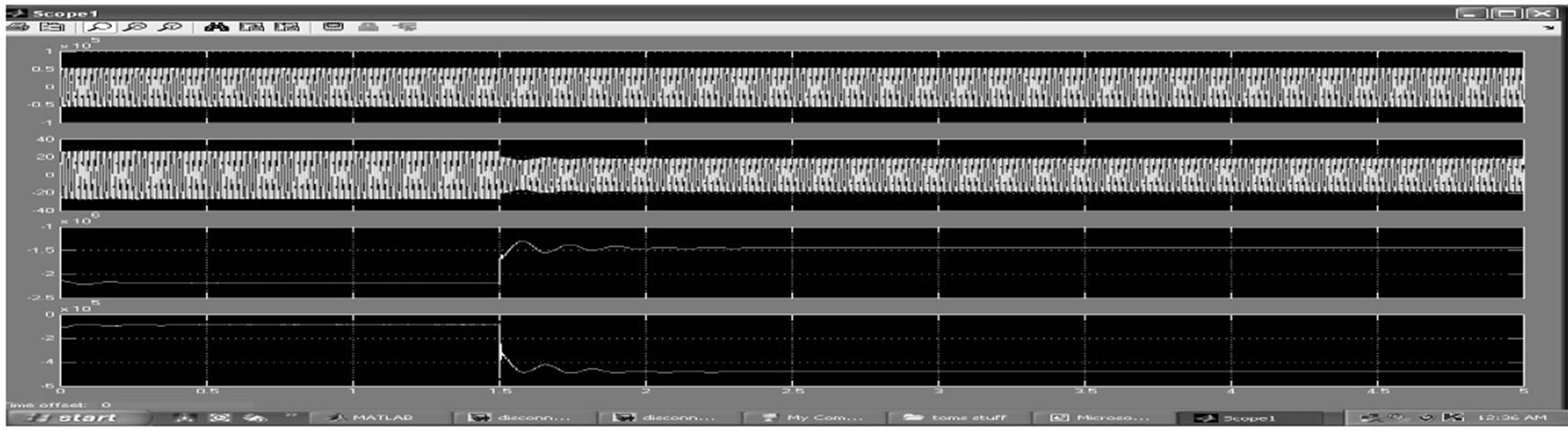
Figure 14. V, I, P & Q waveform at grid end
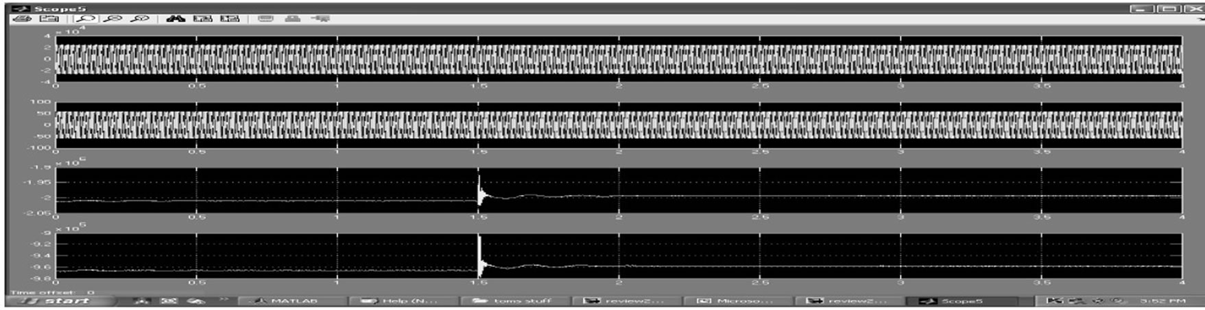
Figure 15. V, I, P & Q waveform at load terminal
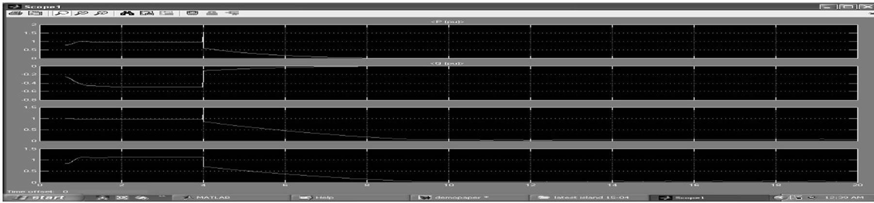
Figure 16. V, I, P, Q waveform at islanded WG end (PL=1.2 MW)
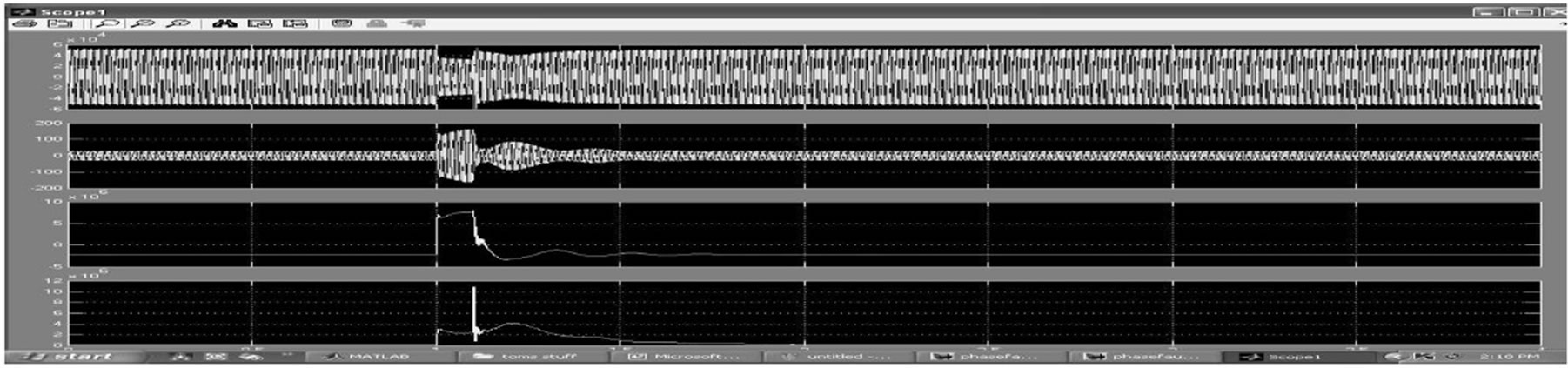
Figure 17. Waveform of V, I, P, Q at Grid terminal during 3 phase fault at t= 1 sec
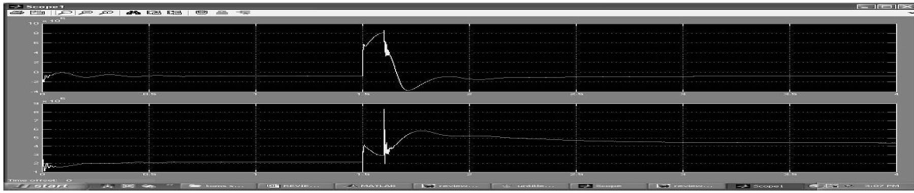
Figure 18. Waveform of P, Q at grid terminals during 3 phase fault at t=1 sec (wind farm capacity= 4.5MW, grid =25MVA)
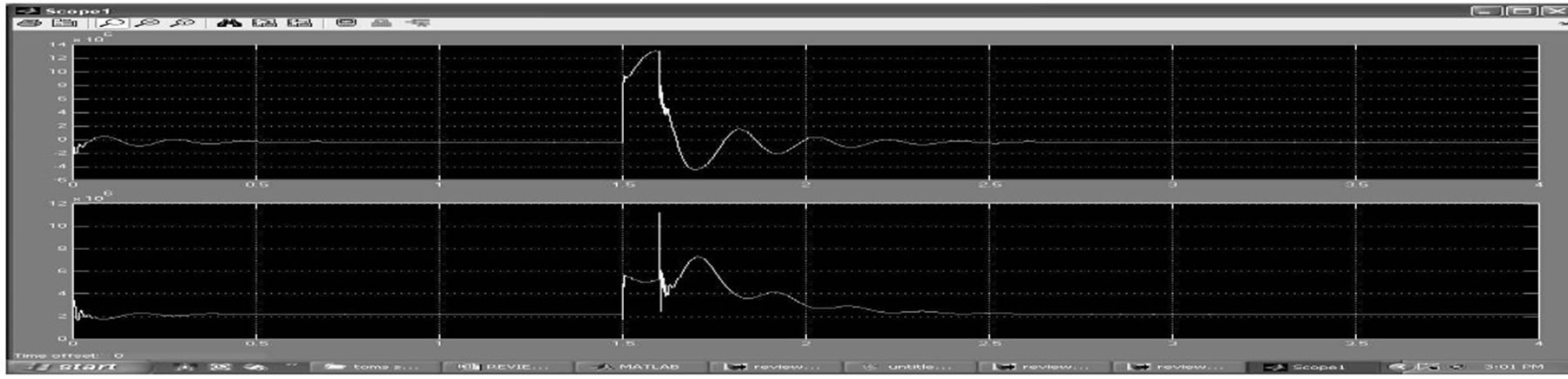
Figure 19 Waveform of P, Q at grid terminals during 3 phase fault at t=1 sec (wind farm capacity=4.5MW, grid=50MVA)
Table 8 shows the IEEE Standards for Interconnection system response to abnormal frequencies.
The Impact of 3-phase to ground fault is analyzed by considering the Wind Farm Capacity of 2.25MW and 4.5MW.
3.4 Wind Farm Capacity of 2.25MW
In Figure 17, response of 3 phase fault at grid terminals is shown when the capacity of wind farm is 2.25 MW & that of Grid is 25MVA. The fault is initiated at t= 1sec & gets self cleared at t=1.1sec.
3.5 Wind Farm Capacity of 4.5MW
When the capacity of the grid is doubled to 50 MVA, following response is obtained at grid terminals.
4. Conclusions
This paper demonstrates the impact of islanding duringpower evacuation from wind turbines. It is found that the problems associated with power evacuation from wind farms entirely depends on the network topology. A Smaller generating system (i.e. for 2.25MW) can sustain and function stably with a grid capacity of 25MVA. To keep the system in stable, the grid capacity has to be increased doubly (i.e. 50 MVA). It is found that Index based methods for anti-islanding doesn’t ensure prevention from islanding as Index threshold could change due to change in system load, generation and configuration. The Voltage based Anti-Islanding technique fails to detect Islanding if the transfer of reactive power from grid to wind farm is kept minimum. The Islanding of single wind turbine has very little impact on nearby wind turbines and grid if it is detected in the given time.
The impact of three phase fault power evacuation from wind turbines is found that the problems associated with power evacuation from wind farms entirely depends on the network topology.
When the capacity of the Wind farm is doubled, system events results in unstable operation of the network. Instability can be seen from the changed operation condition after the fault is cleared at 100ms. The impact is minimised by increasing the capacity of the grid to 50 MVA.
The oscillation in frequency is not acceptable where deviation is more than 5 Hz. Maximum oscillation is observed when the wind farm capacity is observed when the wind farm capacity is 4.5 MW.
REFERENCES
- S. Santoso and H. T. Le, “Fundamental time-domain wind turbine models for wind power studies,” Renewable
- Energy 32, pp. 2436-2452, 2007.
- K. C. Divya and P. S. N. Rao, “Models for wind turbine generating systems and their application in load flow studies,” Electric Power Systems Research 76, pp. 844-856, 2006.
- C. Diduch, J. Yin, and L. C. Chang, “Recent developments in islanding detection for distributed power generation,” Large Engineering Systems Conference, pp. 124-128, 2004.
- S. I. Jang and K. H. Kim, “An islanding detection method for distributed generations using voltage unbalance and total harmonic distortion of current,” IEEE Transactions on Power Delivery, Vol. 19, No. 2, April 2004.
- IEEE Standard 15477M, “Standard for interconnecting distributed resources with electric power systems,” June 2003.
- N. Farhan, A. Rajesh, and V Y. Mohammad, “Unintentional islanding and comparison of prevention techniques,” Proceedings of 37th Annual North American Conference, pp. 90-96, 2005.
- R. A. Walling and N. W. Miller, “Distributed generation islanding-implications on power system dynamic performance,” Proceedings of the IEEE/PES, Summer Power Meeting, Chicago, July 2002.
- S. Panda and N. P. Padhy, “Investigating the impact of wind speed on active and reactive power penetration to the distribution network,” International Journal of Electrical Systems Science and Engineering, Vol. 1, No. 1, ISSN 1307-8917, 2008.