Journal of Software Engineering and Applications
Vol.6 No.4(2013), Article ID:30306,5 pages DOI:10.4236/jsea.2013.64023
A Separating Algorithm for Overlapping Cell Images
![]()
1Department of Electronic Communication Technology, Shenzhen Institute of Information Technology, Shenzhen, China; 2Institute of Optoelectronic Engineering, Jinan University, Guangzhou, China.
Email: fanfrieada@yahoo.com.cn
Copyright © 2013 Jinping Fan et al. This is an open access article distributed under the Creative Commons Attribution License, which permits unrestricted use, distribution, and reproduction in any medium, provided the original work is properly cited.
Received December 23rd, 2012; revised January 25th, 2013; accepted February 3rd, 2013
Keywords: Cell Image; Overlapping; Separation; Convexity Closure; Erosion Limit
ABSTRACT
The cell overlapping and adhesion phenomenon often exists in cell image processing. Separating overlapped cell into single ones is of great important and difficult in cell image quantitative analysis and automatic recognition. In this paper, an algorithm based on concave region extraction and erosion limit has been proposed to judge and separate overlapping cell images. Experimental results show that the proposed algorithm has a good separation effects on analog cell images. Then the method is applying in actual cervical cell image and obtains good separation result.
1. Introduction
Worldwide, especially in middle and low income countries, cervical cancer is the second most common cancer in women, and the third most frequent cause of cancer death, accounting for nearly 300,000 deaths annually. But cervical cancer is more preventable than others because it has a very long time precancerous stage and can be easily detected by a routine screening test. Cervical smear screening is the most popular method to detect the cervical pre-cancers and cancer from the cell abnormalities. However, the conventional manual screening methods are costly and mainly rely on the pathologist subjective experiences, which always result in inaccurate diagnosis. Therefore, it is necessary to develop the automated cervical smear screening analysis system to assist the diagnosis of cervical cancer.
While because of the slice-making, staining techniques and image collection means differences, the overlapping and adhesion phenomenon often appears in cervical cell images. The clustered cell will affect the following quantitative analysis and automatic recognition of cervical cell image. Separating the adherent cells into single ones is a great important and difficult task in cervical cell image processing. According to different characteristics of image, some researchers proposed some methods to process the overlapping cell [1-6], which contained gray scale threshold, region growing method, mathematical morphology, watershed algorithm, and edge detection method and so on. But cervical smear images are frequently con-taminated and the contrast between cell nucleus and cytoplasm is lower, which makes the contours of nuclei and cytoplasm very vague especially for the abnormal cells. So these methods can’t separate the overlapping cervical cell images effectively. In this paper, we propose a separating algorithm according to the concavity and convexity of overlap cell and limit erosion. Linking the separating dotted pair which constructed by concave points we can separate single cells from overlapped cells. The experiment result shows that the algorithm can separate the cell cluster successfully. The method we proposed in this paper is aim to the overlapping cells on a single plane, so the up and down overlapping is not considered in this paper.
2. Overlapping Judgment
2.1. Overlapping Cell Images Category
Before the separation of cell images into cell nuclei and cell cytoplasm, we should judge firstly whether the cells are overlapping or not. For cell image, the overlapping judgment is focus on cell body or cell nucleus, so we set the extracted cell body’s or cell nucleus’s pixel value with 1 and the background value with 0 and we can get a binary image. To simplify the procedure, we first investigate the analog cell images and then separate the actual overlapping cell images.
For most cell images, the overlapping cell may be classified into 3 categories: series cell, parallel cell and series parallel cell. Series cell represent the cells connected head and tail and didn’t form a closed region, while parallel cell represent the cells lapped with other two cells, in most cases the overlapping part is a closed region, in some special cases there is a distinct hole in the overlapping part. Series and parallel cell include series and parallel overlapping. The overlapping cell images are showing in Figure 1. In this paper, we are mainly discussing the series cell and parallel cell separation algorithm.
2.2. Overlapping Cell Image Judgment
Seeing from the overlapping cell images shown in Figure 1, we can find that no matter what kind of overlap there are concave phenomena in the overlapped zone and there exists at least two concave points. We can judge the overlap by the number of concave points which can be described by convexity closure easily. Define concave regions as the domains that subtract the original cell from its convexity closure. For a single cell, its convexity closure is itself and there is no concave region. For overlapping cell there are more than two concave regions. So we can judge the cell overlap by the numbers of concave regions, which shows in Figure 2.
Figure 3 shows the concave regions of series cell and parallel cell. Figure 3(a) is a 2-series cell which composed by two cells, two concave regions are obtained by convexity closure and are show in Figure 3(b). Figure 3(c) is a 3-series cell which composed by 3 cells, while four concave regions are obtained by subtracting Figure 3(c) from its convexity closure. So we can get a conclusion that for series cell, if the number of overlapping cells is n, then the number of concave regions is 2n − 2. Figures 3(e) and (g) are 3-parallel and 4-parallel cells which composed by 3 and 4 overlapping cells respectively, the numbers of concave regions are 3 and 4. We can estimate that for parallel cell which has closed region, if the number of overlapping cells is n, then the number of concave regions is n too. While for the parallel cell with a hole inside in the procedure of concave regions extraction we didn’t take the inner blank region into account, so we can get the additional inner blank region except for the concave regions. In this condition if the number of overlapping cells is n, then the number of ex-
 (a)
(a) (b)
(b) (c)
(c)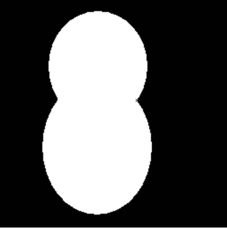 (d)
(d)
Figure 1. Overlapping cell images. (a): Series cell; (b): Parallel cell (closed); (c): Parallel cell (hole); (d): Series parallel cell.
 (a)
(a)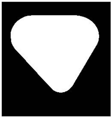 (b)
(b) (c)
(c)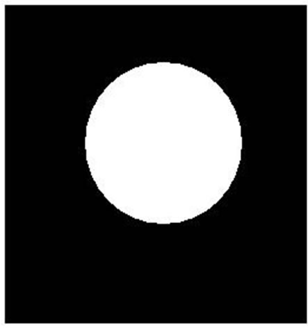 (d)
(d)
Figure 2. Overlapping judgment. (a): Single cell; (b): Parallel cell (closed); (c): Convexity closure; (d): Concave regions.
 (a)
(a) (b)
(b) (c)
(c) (d)
(d) (e)
(e) (f)
(f) (g)
(g) (h)
(h) (i)
(i) (j)
(j) (k)
(k) (l)
(l) (m)
(m) (n)
(n) (o)
(o) (p)
(p) (q)
(q) (r)
(r)
Figure 3. Overlapping types judgment. (a), (d): Series cell; (g), (j): Parallel cell (closed); (m), (p): Parallel cell (hole); (b), (e), (h), (k), (n), (q): Convexity closure; (c), (f), (i), (l), (o), (r): Concave regions.
tracted regions is n + 1, show in Figures 3(o) and (r) respectively.
3. Overlapping Separation
In this section, erosion limit is combined with concave regions to segregate the overlapping cell. Utilizing erosion limit we could get the number of overlapped cells n, integrating with the number of concave regions N we could judge the classification of overlapping, and then we could separate the overlapping cell according to its classification. If N = 2n − 2 then we judge it as series cell, if N = n then judge it as parallel cell with no hole inside, if N = n + 1 then judge it as parallel cell with a hole inside. But in some special cases, for the high degree parallel cell which overlapping part is a closed region as Figures 4(e) and (f), we can not get the right number of overlapped cells which always equal to one, so if n = 1, N ≠ n then we judge the overlapping cell as parallel cell with no hole inside.
3.1. Series Cell Images Separation
For the easiest 2-series cell separation show in Figure 5, two concave regions are extracted and two concave points that have shortest linear distance are located at the most depression point of concave regions. Connect the two concave points we could segregate the single cell. Let (x1, i, y1, i) denote the point coordinates on the first
 (a)
(a) (b)
(b) (c)
(c) (d)
(d) (e)
(e) (f)
(f) (g)
(g) (h)
(h) (i)
(i) (j)
(j) (k)
(k) (l)
(l)
Figure 4. Erosion limit result. (a)-(f): Original cell binary image; (g)-(l): Erosion limit result.
contour of concave region, (x2, i, y2, i) denote the point coordinates on the second contour of concave region, then the shortest linear distance of the two concave regions can be represented as
 (1)
(1)
where (x1, y1) and (x2, y2) are corresponding concave points. Connected the two concave points with a separation line we could separate the two single cell respectively show in Figures 5(e), (f) and (k), (l).
For series cell whose numbers of overlapped cells are more than 2, the separation procedure is more difficult because there existing the concave regions matching problem. In this section we just investigate the 3-series overlapping cell separation shown in Figure 6. Firstly extracting the cell kernels of overlapped cell by erosion limit and then computing the concave regions, at last we can get 3 cell kernels and 4 concave regions. The contour of concave regions and 3 cell kernels is shown in Figure 6(b) and its schematic diagram shown in Figure 6(c). Let capital letters A, B and C denote the three cell kernels and numbers 1 - 4 denote the four concave regions, we can get the conclusion that the matching concave regions 1 and 2 are between cell kernels A and B, the matching concave regions 3 and 4 are between cell kernels B and C. The distance difference of concave region 1 or 2 to the adjacent cell kernels A and B is much smaller than the distance difference of concave region 1 or 2 to cell kernels A (or B) and C. Similarly the distance difference of concave region 3 or 4 to the adjacent cell kernels B and C is much smaller than the distance difference of concave region 3 or 4 to cell kernels B (or C) and A. According to this rule we can get the matching concave regions. On the basis of shortest distance, connecting the paired concave points we can get the single cells separated shown in Figures 6(f)-(h).
3.2. Parallel Cell Images Separation
For the parallel cell with no hole, the overlapped part is located at the internal of overlapping region. As the number of overlapped cells equal to the number of con-
 (a)
(a) (b)
(b)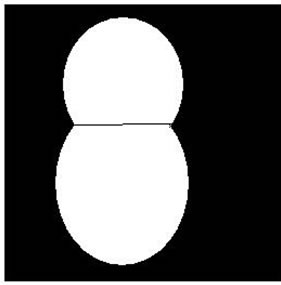 (c)
(c) (d)
(d)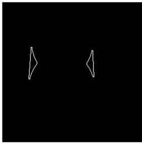 (e)
(e) (f)
(f) (g)
(g) (h)
(h) (i)
(i) (j)
(j) (k)
(k) (l)
(l)
Figure 5. Two-series cell separation result. (a), (f): Original cell binary image; (b), (h): Concave regions contour; (c), (i): Concave points connection; (d), (j): Overlapping cell separation; (e), (f), (k), (l): Separated single cell.
 (a)
(a) (b)
(b) (c)
(c) (d)
(d) (e)
(e) (f)
(f) (g)
(g) (h)
(h)
Figure 6. Three-series cell separation result. (a): 3-series cell binary image; (b): Cell kernel and concave regions contour; (c): Schematic diagram; (d): Concave points connection; (e): Overlapping cell separation; (f)-(h): Separated single cell.
caved regions, the separation method of series cell can’t be used in parallel cell separation. Observing the parallel cell image we can find that if connected the centre of overlapping cell with each concave points, one can segregate single cells. In this condition, the searching of concave points is in terms of shortest distance between the centre of overlapping cell and each concave region. The centre of the overlapping cell could be calculated with a simple method. In cell binary image, the pixel value of objective cell is 1 and the background is 0, so compute the average coordinate of the region whose pixel value is one we can get the center coordinate. The procedure of parallel cell separation is shown in Figure 7.
For parallel cell with hole inside, in the procedure of concave regions extraction, the inner blank region being extracted simultaneously. Before the separation, we should judge which region is the concave region and which one is inner blank region. Seeing from Figure 8 we could find that the centre of overlapping cell is inside the inner region and the distance between them is shorter than the distance between the centre of overlapping cell and concave region. According to this rule, we can find the inner blank region. By computing the shortest distance between the inner region and surrounded concave region, the paired separated points can be founded. Connecting the matched separated points, we could segregate single cells.
The flow chart of the proposed method could be simplified as Figure 9.
4. Overlapping Cervical Cell Images Separation
There are two main overlapping modes in cervical cell images. One is the overlap of cell body, and the other is the overlap of cell nucleus. Above sections we introduce the separation method on analog series and parallel cells, the simulated experiment shows that the method introduced can judge and separate the overlapping images successfully. In this section we will verify the algorithm mentioned above using actual cervical cell images. The experiment results are shown in Figures 10-12 which shows that the algorithm can separate the overlapping cervical cell body or nucleus successfully.
5. Conclusion
In this paper, a digital method for overlapping cell images separation based on convexity closure and erosion limit has been proposed. Numerical simulation results for
 (a)
(a) (b)
(b)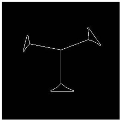 (c)
(c) (d)
(d) (e)
(e) (f)
(f)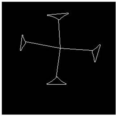 (g)
(g) (h)
(h)
Figure 7. Parallel cell (no hole) separation result. (a), (e): Parallel cell (no hole) binary image; (b), (f): Cell centre and concave regions contour; (c), (g): Separating points connection; (d), (h): Overlapping cell separation.
 (a)
(a) (b)
(b)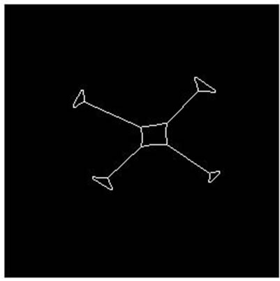 (c)
(c) (d)
(d) (e)
(e)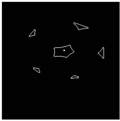 (f)
(f)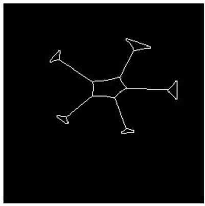 (g)
(g) (h)
(h)
Figure 8. Parallel cell (hole) separation result. (a), (e): Parallel cell (hole) binary image; (b), (f): Cell centre and concave regions contour; (c), (g): Separating points connection; (d), (h): Overlapping cell separation.

Figure 9. The flow chart of the proposed method.
 (a)
(a)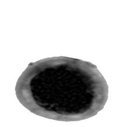 (b)
(b) (c)
(c) (d)
(d) (e)
(e) (f)
(f) (g)
(g) (h)
(h) (i)
(i) (j)
(j) (k)
(k) (l)
(l) (m)
(m) (n)
(n) (o)
(o) (p)
(p)
Figure 10. Two-series cervical cell body separation result. (a), (b): Two-series cervical cell image; (b), (j): Cell body contour curve; (c), (k): Binary image of the cervical cell; (d), (l): Concave regions of the cell body; (e), (m): Concave points connection; (f), (g): Overlapping cell separation; (g), (h), (o), (p): Separated single cell.
 (a)
(a) (b)
(b)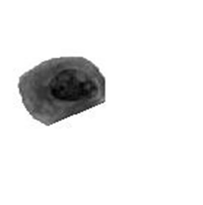 (c)
(c) (d)
(d) (e)
(e) (f)
(f) (g)
(g) (h)
(h) (i)
(i)
Figure 11. Three-parallel cervical cell body (no hole) separation result. (a): Three-parallel cervical cell image; (b): Cell body contour curve; (c): Binary image of the cervical cell; (d): Concave regions of the cell body; (e): Separating points connection; (f): Overlapping cell separation; (g)-(i): Separated single cell.
 (a)
(a) (b)
(b) (c)
(c) (d)
(d)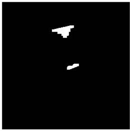 (e)
(e) (f)
(f) (g)
(g) (h)
(h)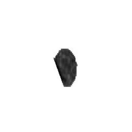 (i)
(i) (j)
(j) (k)
(k) (l)
(l) (m)
(m) (n)
(n) (o)
(o) (p)
(p)
Figure 12. Two-series cervical cell nucleus separation result. (a), (b): Two-series cervical cell image; (b), (j): Cell body contour curve; (c), (k): Binary image of the cervical cell; (d), (l): Concave regions of the cell body; (e), (m): Concave points connection; (f), (g): Overlapping cell separation; (g), (h), (o), (p): Separated single cell nucleus.
analog overlapping cell images separation are given to demonstrate the validity of the proposed method. Then the actual overlapping cervical cell images which contained cell body overlap and cell nucleus overlap are separated with the same method to verify the feasibility of the algorithm. It’s observed that the algorithm can separate the overlapping cell successfully. In the numerical experiment we also find that if the number of overlapping cervical cells is more than 6 and one cell nuclei is overlapping with another cell nuclei, it’s hard to judge each nuclei belongs to which cell, in that situation the method we proposed is also hard to separate the overlapping cell accurately.
REFERENCES
- A. Bieniek and A. Moga, “An Efficient Watershed Algorithm Based on Connected Conponents,” Pattern Recognition, Vol. 33, No. 6, 2000, pp. 907-916. doi:10.1016/S0031-3203(99)00154-5
- N. Malpica, C. O. Solorzano, J. J. Vaquero, et al., “Applying Watershed Algorithm to the Segmentation of Clustered Nuclei,” Cytometry, Vol. 28, No. 4, 1997, pp. 289- 297. doi:10.1002/(SICI)1097-0320(19970801)28:4<289::AID-CYTO3>3.0.CO;2-7
- H. Song and W. X. Wang, “A New Separation Algorithm for Overlapping Blood Cells Using Shape Analysis,” Internal Journal of Pattern Recognition and Artificial Intelligence, Vol. 23, No. 4, 2009, pp. 847-864. doi:10.1142/S0218001409007302
- K. Z. Mao, P. Zhao, T. S. Koh and P. H. Tan, “Overlapping/Touching Cell Nuclei Segmentation Based on Analysis of Perpendicular Distance Curve,” IEEE EMBS Asian-Pacific Conference on Biomedical Engineering, 20-22 October 2003, pp. 212-213. doi:10.1109/APBME.2003.1302659
- E. Bengtsson, O. Eriksson, J. Holmquise, T. Jarkrans, B. Bordin and B. Stenkvist, “Segmentation of Cervical Cells: Detection of Overlapping Cell Nuclei,” Computer Graphics and Image Processing, Vol. 16, No. 4, 1981, pp. 382- 394. doi:10.1016/0146-664X(81)90048-4
- W. F. Clocksin, “Automatic Segmentation of Overlapping Nuclei with High Background Variation Using Robust Estimation and Flexible Contour Models,” 12th International Conference on Image Analysis and Processing, 2003, pp. 682-687.