J. Q. WANG ET AL.
Copyright © 2013 SciRes. EPE
1071
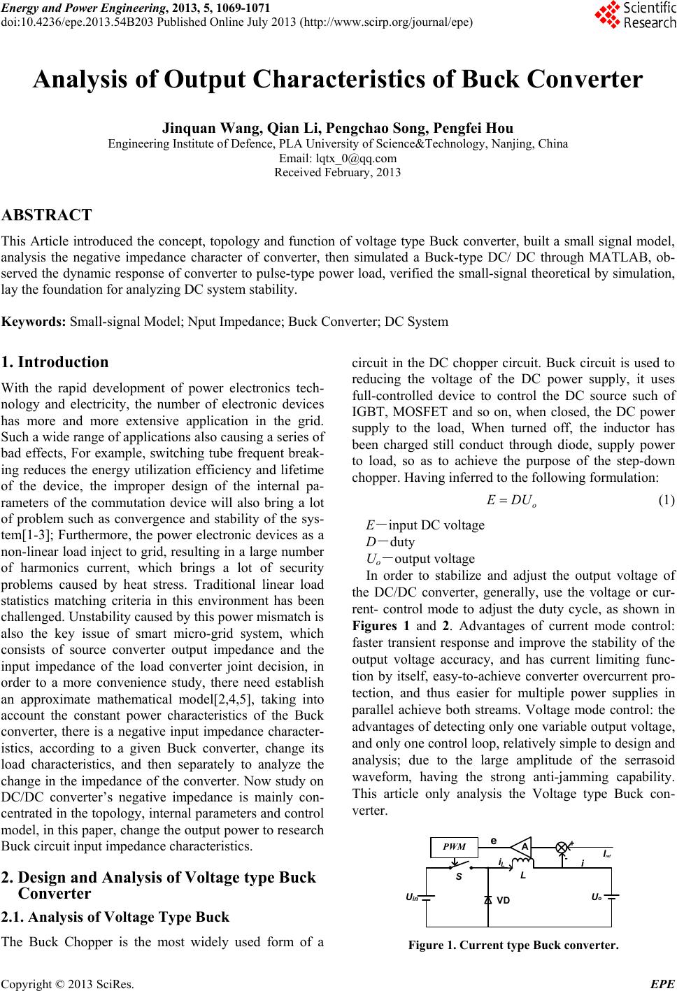
Figure 4. Simulation model.
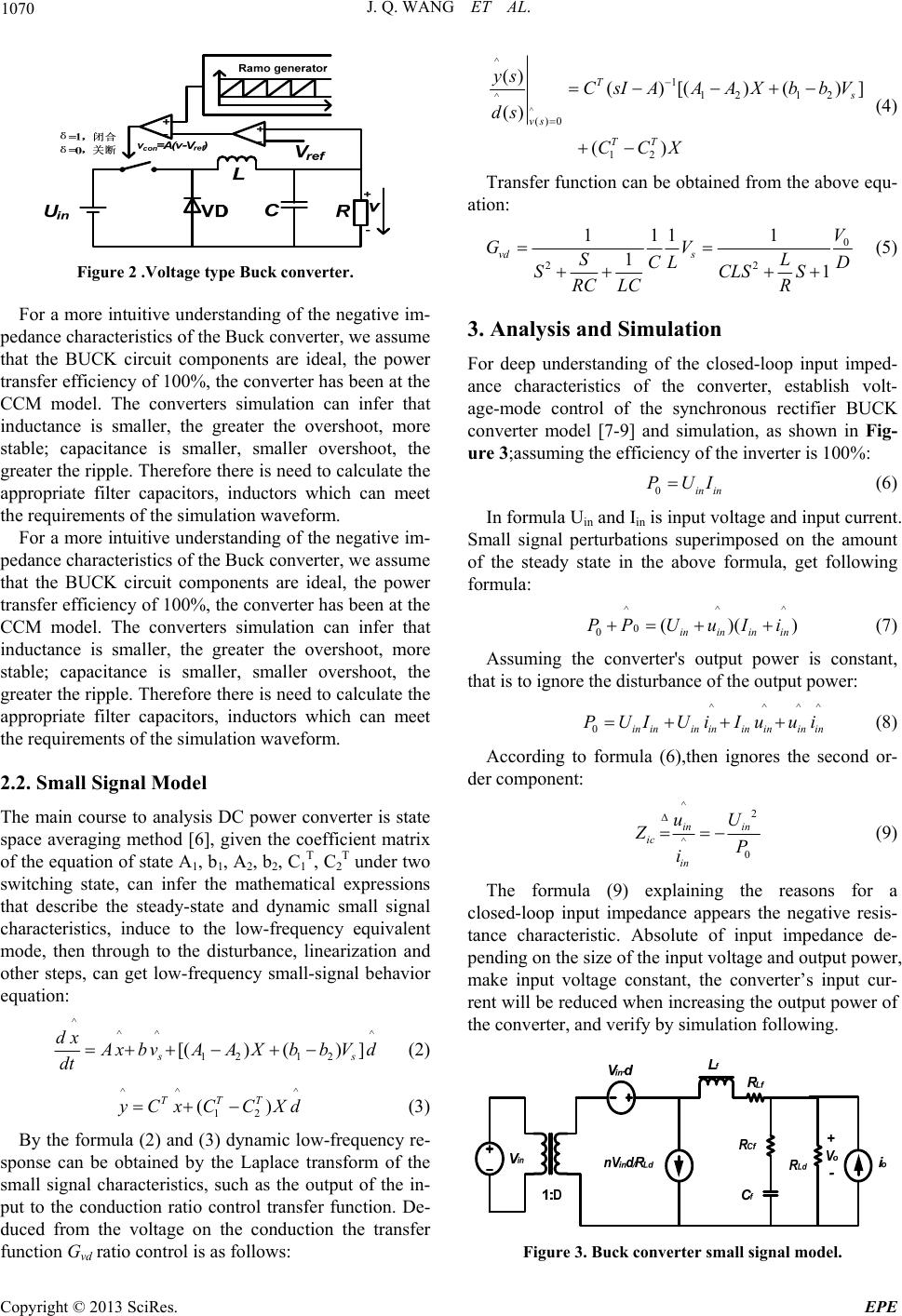
Figure 5. Current waveform.
In Buck converter simulation, set the voltage feedback
loop control system, the converter input voltage E = 200
V, output voltage Uo = 120 V, the initial resistive load is
1.5 Ω, due to it is assumed that the converter has been
working in CCM state[10-12], according to inductance
L、C of formula, it can obtain the value of the L, C, and
then multiplied by a certain margin coefficient, and fi-
nally set L = 6e-5 H, C = 5e-4F,make simulation time is
0.02 seconds, and paralle a plurality of resistive load in
the load terminal, then trigger pulse at different times, the
purpose of increasing the load is to observe the change of
the input current, and the validation of the negative im-
pedance characteristics. The simulation model is shown
in Figure 4.
4. Results of Simulation
Since the input voltage is maintained at 200 V, only ob-
serve the input current, the increase resistive load added
in 0.002 s, 0.005 s, 0.01 s, taking into account the effi-
ciency of the inverter is 100%, The obtained current
waveform is shown in Figure 5.
Seen by the waveform diagram of the current in the
load side of the power increase, the average of the input
current increases, the input voltage to maintain the same
circumstances, and seen by the Ohm’s law, the input re-
sistance of the converter decreases, showing negative
impedance characteristics.
5. Results of Simulation
It get the same conclusion whether in theoretical way or
simulation way, the voltage Buck converter exhibit nega-
tive impedance characteristics. In order to avoid the ad-
erse effects of the negative impedance characteristics in
engineering, They often put filter in the converter pre-
ceding, increasing the positive impedance to counteract
the negative impedance converter produced, It lead us to
use Buck converter input impedance characteristics to the
next research, such as provides a good reference for
study on DC bus stability.
REFERENCES
[1] H. Sira-Ramirez, “Slind Motions in Bilinear Swithed
Networks,” IEEE Transactions on Circuits Systems, Vol.
34, No. 8, 1987, pp. 919-933.
[2] X. Feng, et al.,“Individual Load Impedance Specification
for a Stable DC Distributed Power System,” IEEE APEC
Record,1999.
[3] J. Sun and H. Grotstollen, “Symbolic Analysis of Switch-
ing Power Converters Based on a General Averaging
Method,” Power Electronics Specialists Conference, 27th
Annual IEEE, Vol. 1, 23-27 June 1996, pp. 543-549
[4] B. Gao, G. K. Morison and K. P. Voltage, “Stability
Evaluation Using Model Analysis,” IEEE Transactions
on PWS, Vol. 17, No. 4, 1992, pp. 1529-1536.
[5] D. Czarkowki, L. R. Pjara and M. K. Kazimierczuk, “Ro-
bust Stability of State-feedback Control of PWM DC-DC
Push-pull Converter,” IEEE Transactions on Industrial
Electronics, Vol. 42, No. 1, 1995, pp.108-111.
doi:10.1109/41.345854
[6] F. L. Luo and H. Ye, “Positive Output Super-lift Con-
verters,” IEEE Transactions on Power Eletronics, Vol. 18,
No. 1, 2003, pp. 105-113.
doi:10.1109/TPEL.2002.807198
[7] F. Z. Peng, J. S. Lai and J. W. Mckeever, “A Multilevel
Voltage Source Inverter with Separate DC Source for
Static Var Generation,” IEEE Transactions on Industry
Applications, 1996.
[8] T. C. Neugebauer, J. W. Phinney and D. J. Perreault,
“Filters and Components with Inductance Cancellation,”
IEEE Transactions on Industry Applications, Vol. 40, No.
2, 2004, pp. 483-491. doi:10.1109/TIA.2004.824487
[9] Z. H. Zhao and W. M. Ma, “Coupling Model and Imped-
ance Calculation of the Steel Ground Loops with Prox-
imity Effect,” IEEE Transactions on Electromagnetic
Compatibility, Vol. 48, No. 3, 2006, pp. 522-529.
doi:10.1109/TEMC.2006.877780
[10] E. Porter, S. Ang, K. Burgers, et al.,“Miniaturizing
Power Electronics using Multi-chip Module Technol-
ogy,” Proceedings of International Conference on Mul-
tichip Modules,1997.
[11] S. Wang, F. C. Lee and W. G. Odendaal, “Characteriza-
tion and Parasitic Extraction of EMI Filters Using Scat-
teringParameters,” IEEE Transactions on Power Elec-
tronics,Vol. 20, No. 2, 2005, pp.
502-510.doi:10.1109/TPEL.2004.842949
[12] C. Batlle, E. Fossas and G. Olivar, “Stabilization of Peri-
odic Orbits in Variable Structure Systems Application to
DC/DC Power Converters,” MAU-UPC-01/96,1996.
v