Paper Menu >>
Journal Menu >>
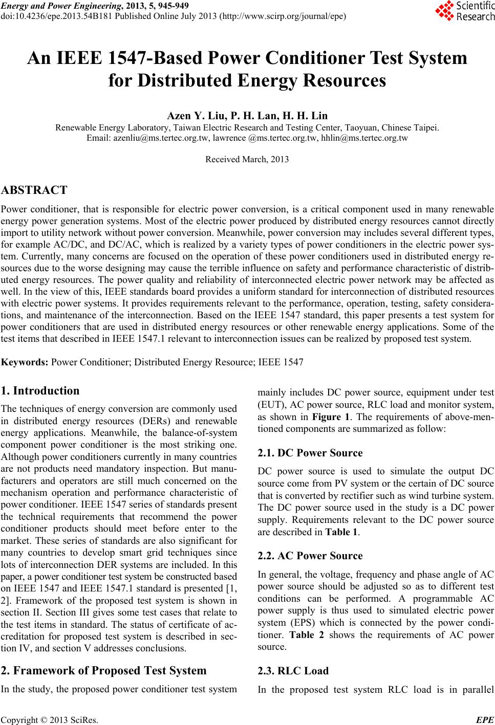 Energy and Power Engineering, 2013, 5, 945-949 doi:10.4236/epe.2013.54B181 Published Online July 2013 (http://www.scirp.org/journal/epe) An IEEE 1547-Based Power Conditioner Test System for Distributed Energy Resources Azen Y. Liu, P. H. Lan, H. H. Lin Renewable Energy Laboratory, Taiwan Electric Research and Testing Center, Taoyuan, Chinese Taipei. Email: azenliu@ms.tertec.org.tw, lawrence @ms.tertec.org.tw, hhlin@ms.tertec.org.tw Received March, 2013 ABSTRACT Power conditioner, that is responsible for electric power conversion, is a critical component used in many renewable energy power generation systems. Most of the electric power produced by distributed energy resources cannot directly import to utility network witho ut power conversion. Meanwhile, power conversion may includ es several d ifferen t types, for example AC/DC, and DC/AC, which is realized by a variety types of power conditioners in the electric power sys- tem. Currently, many concerns are focused on the operation of these power conditioners used in distributed energy re- sources due to the worse designing may cause the terrible influence on safety and performance characteristic of distrib- uted energy resources. The power quality and reliability of interconnected electric power network may be affected as well. In the view of this, IEEE standards board provides a uniform standard for interconnection of distributed resources with electric power systems. It provides requirements relevant to the performance, operation, testing, safety considera- tions, and maintenance of the interconnection. Based on the IEEE 1547 standard, this paper presents a test system for power conditioners that are used in distributed energy resources or other renewable energy applications. Some of the test items that described in IEEE 1547.1 relevant to interconnection issues can be realized by proposed test system. Keywords: Power Conditioner; Distributed Energy Resource; IEEE 1547 1. Introduction The techniques of energy conversion are commonly used in distributed energy resources (DERs) and renewable energy applications. Meanwhile, the balance-of-system component power conditioner is the most striking one. Although power conditione rs currently in many countries are not products need mandatory inspection. But manu- facturers and operators are still much concerned on the mechanism operation and performance characteristic of power conditioner. IEEE 15 47 series of standa rds presen t the technical requirements that recommend the power conditioner products should meet before enter to the market. These series of standards are also significant for many countries to develop smart grid techniques since lots of interconnection DER systems are included. In this paper, a power conditioner test system be constructed b ased on IEEE 1547 and IEEE 1547.1 standard is presented [1, 2]. Framework of the proposed test system is shown in section II. Section III gives some test cases that relate to the test items in standard. The status of certificate of ac- creditation for proposed test system is described in sec- tion IV, and section V addresses conclusions. 2. Framework of Proposed Test System In the study, the proposed power conditioner test system mainly includes DC power source, equipment under test (EUT), AC power source, RLC load and monitor system, as shown in Figure 1. The requirements of above-men- tioned components are summarized as follow: 2.1. DC Power Source DC power source is used to simulate the output DC source come from PV system or the certain of DC source that is converted by rectifier such as wind turbine system. The DC power source used in the study is a DC power supply. Requirements relevant to the DC power source are described in Table 1. 2.2. AC Power Source In general, the voltage, frequency and phase angle of AC power source should be adjusted so as to different test conditions can be performed. A programmable AC power supply is thus used to simulated electric power system (EPS) which is connected by the power condi- tioner. Table 2 shows the requirements of AC power source. 2.3. RLC Load In the proposed test system RLC load is in parallel Copyright © 2013 SciRes. EPE 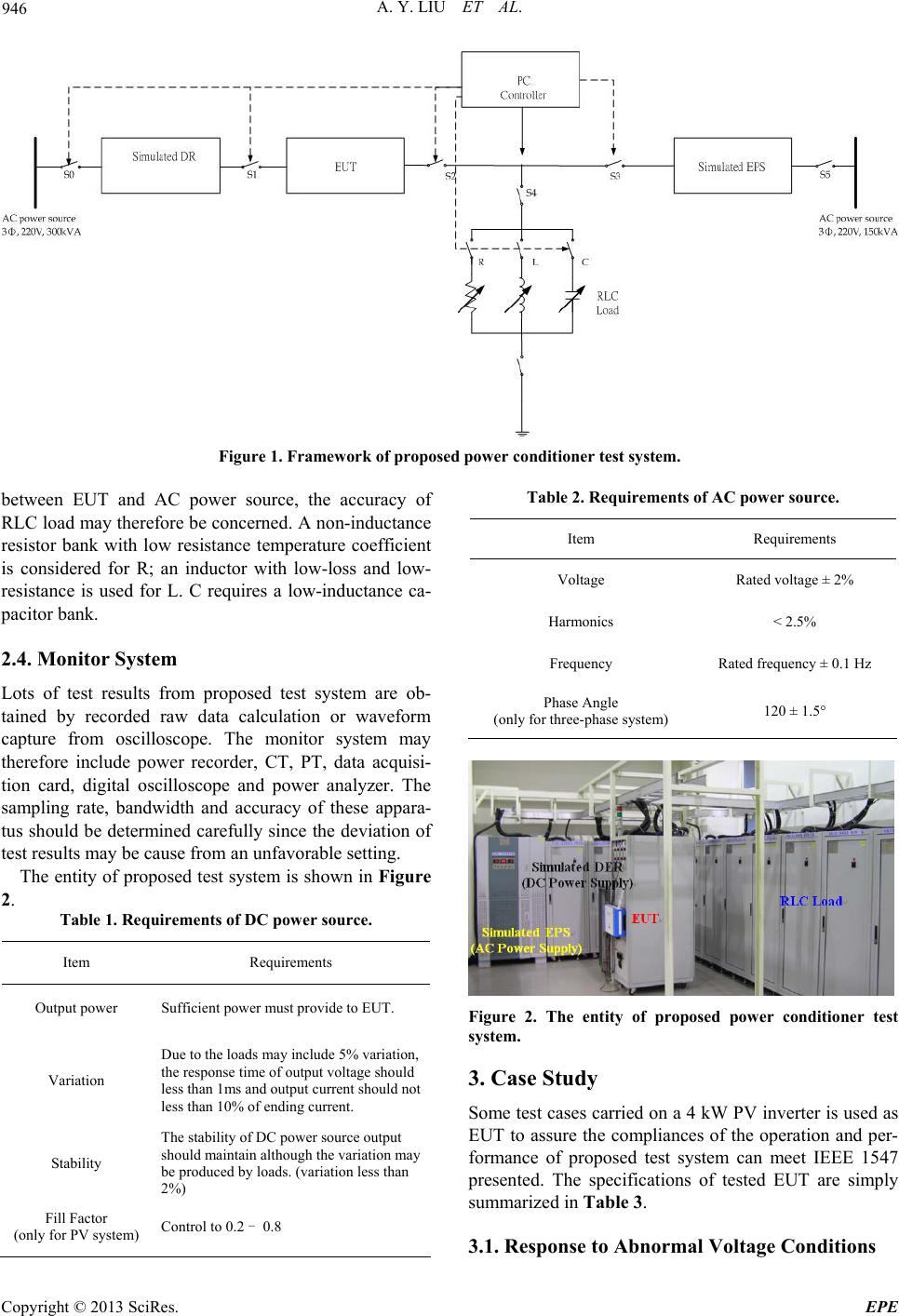 A. Y. LIU ET AL. 946 Figure 1. Framework of proposed power conditioner test system. between EUT and AC power source, the accuracy of RLC load may therefore be concerned. A non-inductance resistor bank with low resistance temperature coefficient is considered for R; an inductor with low-loss and low- resistance is used for L. C requires a low-inductance ca- pacitor bank. 2.4. Monitor System Lots of test results from proposed test system are ob- tained by recorded raw data calculation or waveform capture from oscilloscope. The monitor system may therefore include power recorder, CT, PT, data acquisi- tion card, digital oscilloscope and power analyzer. The sampling rate, bandwidth and accuracy of these appara- tus should be determined carefully since the deviation of test results may be cause from an unfavorable setting. The entity of proposed test syste m is shown in Figure 2. Table 1. Requirements of DC power source. Item Requirements Output power Sufficient power must provide to EUT. Variation Due to the loads may include 5% variation, the response time of output voltage s h o u ld less than 1ms and output current should not less than 10% of ending current. Stability The stability of DC power source output should maintain a l t h o u gh the variation may be produced by loads. (variation less than 2%) Fill Factor (only for PV system) Control to 0.2 - 0.8 Table 2. Requirements of AC power source. Item Requirements Voltage Rated voltage ± 2% Harmonics < 2.5% Frequency Rated frequency ± 0.1 Hz Phase Angle (only for three-phase system) 120 ± 1.5° Figure 2. The entity of proposed power conditioner test system. 3. Case Study Some test cases carried on a 4 kW PV inverter is used as EUT to assure the compliances of the operation and per- formance of proposed test system can meet IEEE 1547 presented. The specifications of tested EUT are simply summarized in Table 3. 3.1. Response to Abnormal Voltage Conditions Copyright © 2013 SciRes. EPE 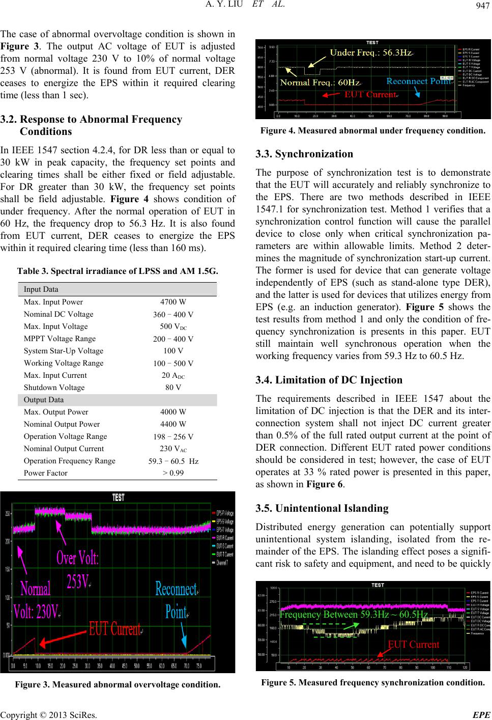 A. Y. LIU ET AL. 947 The case of abnormal overvoltage condition is shown in Figure 3. The output AC voltage of EUT is adjusted from normal voltage 230 V to 10% of normal voltage 253 V (abnormal). It is found from EUT current, DER ceases to energize the EPS within it required clearing time (less than 1 sec). 3.2. Response to Abnormal Frequency Conditions In IEEE 1547 section 4.2.4, for DR less than or equal to 30 kW in peak capacity, the frequency set points and clearing times shall be either fixed or field adjustable. For DR greater than 30 kW, the frequency set points shall be field adjustable. Figure 4 shows condition of under frequency. After the normal operation of EUT in 60 Hz, the frequency drop to 56.3 Hz. It is also found from EUT current, DER ceases to energize the EPS within it required clearing time (less than 160 ms). Table 3. Spectral irradiance of LPSS and AM 1. 5G. Input Data Max. Input Power 4700 W Nominal DC Voltage 360 - 400 V Max. Input Voltage 500 VDC MPPT Voltage Range 200 - 400 V System Star-Up Voltage 100 V Working Voltage Range 100 - 500 V Max. Input Current 20 ADC Shutdown Voltage 80 V Output Data Max. Output Power 4000 W Nominal Output Power 4400 W Operation Voltage Range 198 - 256 V Nominal Output Current 230 VAC Operation Frequency Range 59.3 - 60.5 Hz Power Factor > 0.99 Figure 3. Measured abnormal overvoltage condition. Figure 4. Measured abnormal under frequency condition. 3.3. Synchronization The purpose of synchronization test is to demonstrate that the EUT will accurately and reliably synchronize to the EPS. There are two methods described in IEEE 1547.1 for synchronization test. Method 1 verifies that a synchronization control function will cause the parallel device to close only when critical synchronization pa- rameters are within allowable limits. Method 2 deter- mines the magnitude of synchronization start-up current. The former is used for device that can generate voltage independently of EPS (such as stand-alone type DER), and the latter is used for devices that utilizes energy from EPS (e.g. an induction generator). Figure 5 shows the test results from method 1 and only the condition of fre- quency synchronization is presents in this paper. EUT still maintain well synchronous operation when the working frequency varies from 59.3 Hz to 60.5 Hz. 3.4. Limitation of DC Injection The requirements described in IEEE 1547 about the limitation of DC injection is that the DER and its inter- connection system shall not inject DC current greater than 0.5% of the full rated output current at the point of DER connection. Different EUT rated power conditions should be considered in test; however, the case of EUT operates at 33 % rated power is presented in this paper, as shown in Figure 6. 3.5. Unintentional Islanding Distributed energy generation can potentially support unintentional system islanding, isolated from the re- mainder of the EPS. The islanding effect poses a signifi- cant risk to safety and equipment, and need to be quickly Frequency Between 59.3Hz ~ 60.5Hz EUT Curre n t Figure 5. Measured frequency sy nc hr onization c ondition. Copyright © 2013 SciRes. EPE 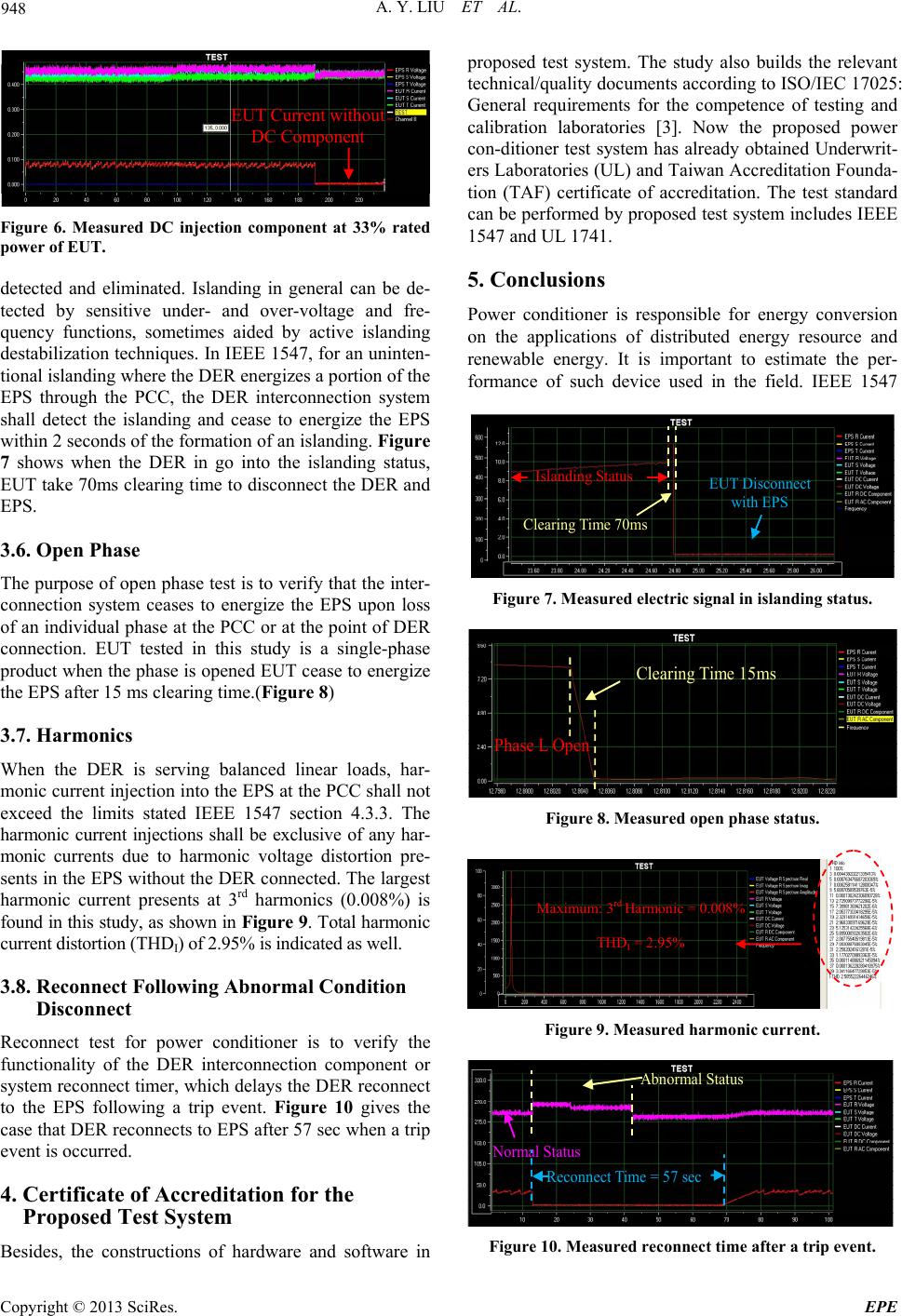 A. Y. LIU ET AL. 948 EUT Current without DC Component Figure 6. Measured DC injection component at 33% rated power of EUT. detected and eliminated. Islanding in general can be de- tected by sensitive under- and over-voltage and fre- quency functions, sometimes aided by active islanding destabilization techniques. In IEEE 1547, for an uninten- tional islanding wh ere the DER en erg izes a portion of the EPS through the PCC, the DER interconnection system shall detect the islanding and cease to energize the EPS within 2 seconds of the formation of an islanding . Figure 7 shows when the DER in go into the islanding status, EUT take 70ms clearing time to disconnect the DER and EPS. 3.6. Open Phase The purpose of open phase test is to verify that the inter- connection system ceases to energize the EPS upon loss of an individual phase at the PCC or at the point of DER connection. EUT tested in this study is a single-phase product when the phase is opened EUT cease to energize the EPS after 15 ms clearing time.(Figure 8) 3.7. Harmonics When the DER is serving balanced linear loads, har- monic current injection into the EPS at th e PCC shall not exceed the limits stated IEEE 1547 section 4.3.3. The harmonic current injections shall be exclusive of any har- monic currents due to harmonic voltage distortion pre- sents in the EPS without the DER connected . The largest harmonic current presents at 3rd harmonics (0.008%) is found in this study, as shown in Figure 9. Total harmonic current distortion (THDI) of 2.95% is indicat ed as well. 3.8. Reconnect Following Abnormal Condition Disconnect Reconnect test for power conditioner is to verify the functionality of the DER interconnection component or system reconnect timer, which delays the DER reconnect to the EPS following a trip event. Figure 10 gives the case that DER reconnects to EPS after 57 sec when a trip event is occurred. 4. Certificate of Accreditation for the Proposed Test System Besides, the constructions of hardware and software in proposed test system. The study also builds the relevant technical/quality documents according to ISO/IEC 17025: General requirements for the competence of testing and calibration laboratories [3]. Now the proposed power con-ditioner test system has already obtained Underwrit- ers Laboratories (UL) and Taiwan Accreditation Founda- tion (TAF) certificate of accreditation. The test standard can be performed by proposed test system includes IEEE 1547 and UL 1741. 5. Conclusions Power conditioner is responsible for energy conversion on the applications of distributed energy resource and renewable energy. It is important to estimate the per- formance of such device used in the field. IEEE 1547 Islanding S t a tusEUT Disconnect with EPS Clearing T ime 70ms Figure 7. Measured electric signal in islanding status. Clearing T ime 15ms Phase L Open Figure 8. Measured open phase status. Maximum: 3 rd Harmonic = 0.008% THD I = 2.95% Figure 9. Measured harmonic current. Normal Status Abnormal Statu s Reconnect Time = 57 sec Figure 10. Measured reconnect time after a trip event. Copyright © 2013 SciRes. EPE  A. Y. LIU ET AL. Copyright © 2013 SciRes. EPE 949 standard presents a guide for interconnecting distributed energy resource with electric power system, and the test procedures and requirements are described in IEEE 1547.1. This paper presents a test system for power con- ditioner based on the technical requirements indicated in IEEE 1547 standard. Some tests cases relate to the test item in IEEE 1547 are presented as well. It is found the proposed test system gives a well performance in test of power conditioner produ cts. REFERENCES [1] IEEE 1547: IEEE standas for interconneting distributed resources with electric power systems , 2003. [2] IEEE 1547.1: IEEE standar conformance test procedures for equipment interconneting distributed resources with electric power systems , 2005. [3] ISO/IEC 17025: General requirements for the compe- tence of testing and calibr ation laboratorie, 2005. |