Paper Menu >>
Journal Menu >>
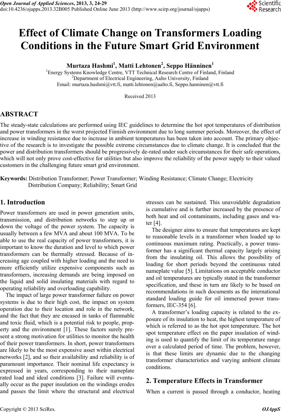 Open Journal of Applied Sciences, 2013, 3, 24-29 doi:10.4236/ojapps.2013.32B005 Published Online June 2013 (http://www.scirp.org/journal/ojapps) Effect of Climate Change on Transformers Loading Conditions in the Future Smart Grid Environment Murtaza Hashmi1, Matti Lehtonen2, Seppo Hänninen1 1Energy Systems Knowledge Centre, VTT Technical Research Centre of Finland, Finland 2Department of Electrical Engineering, Aalto University, Finland Email: murtaza.hashmi@vtt.fi, matti.lehtonen@aalto.fi, Seppo.hanninen@vtt.fi Received 2013 ABSTRACT The steady-state calculations are performed using IEC guidelines to determine the hot spot temperatures of distribution and power transformers in the worst projected Finnish environment due to long summer periods. Moreover, the effect of increase in winding resistance due to increase in ambient temperatures has been taken into account. The primary objec- tive of the research is to investigate the possible extreme circumstances due to climate change. It is concluded that the power and distribution transformers should be progressively de-rated under such circumstances for their safe operations, which will not only prove cost-effective for utilities but also improve the reliability of the power supply to their valued customers in the challenging future smart grid environment. Keywords: Distribution Transformer; Power Transformer; Winding Resistance; Climate Change; Electricity Distribution Company; Reliability; Smart Grid 1. Introduction Power transformers are used in power generation units, transmission, and distribution networks to step up or down the voltage of the power system. The capacity is usually between a few MVA and about 100 MVA. To be able to use the real capacity of power transformers, it is important to know the duration and level to which power transformers can be thermally stressed. Because of in- creasing age coupled with higher loading and the need to more efficiently utilize expensive components such as transformers, increasing demands are being imposed on the liquid and solid insulating materials with regard to operating reliability and overloading capability. The impact of large power transformer failure on power systems is due to their high cost, the impact on system operation due to their location and role in the network, and the fact that they are encased in tanks of flammable and toxic fluid, which is a potential risk to people, prop- erty and the environment [1]. These factors surely pre- sent a strong motivation for utilities to monitor the health of their power transformers. In short, power transformers are likely to be the most expensive asset within electrical networks [2], and so their availability and reliability is of paramount importance. Their nominal life expectancy is expressed in years, corresponding to their nameplate rated load and ideal conditions [3]. Failure will eventu- ally occur as the paper insulation on the windings erodes and passes the limit where the structural and electrical stresses can be sustained. This unavoidable degradation is cumulative and is further increased by the presence of both heat and oil contaminants, including gases and wa- ter [4]. The designer aims to ensure that temperatures are kept to reasonable levels in a transformer when loaded up to continuous maximum rating. Practically, a power trans- former has a significant thermal capacity largely arising from the insulating oil. This allows the possibility of loading for short periods beyond the continuous rated nameplate value [5]. Limitations on acceptable conductor and oil temperatures are typically stated in the transformer specification, and these in turn are likely to be based on recommendations in such documents as the international standard loading guide for oil immersed power trans- formers, IEC-354 [6]. A transformer’s loading capacity is related to the ex- posure of its insulation to heat, the highest temperature of which is referred to as the hot spot temperature. The hot spot temperature effect on the paper insulation of wind- ing is used to quantify the limit of its temperature range over a calculated period of time. The problem, however, is that these limits are dynamic due to the changing transformer characteristics and varying ambient climate conditions. 2. Temperature Effects in Transformer When a current is passed through a conductor, heating Copyright © 2013 SciRes. OJAppS 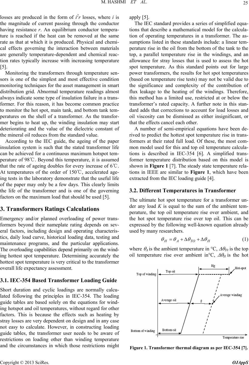 M. HASHMI ET AL. 25 losses are produced in the form of i2r losses, where i is the magnitude of current passing through the conductor having resistance r. An equilibrium conductor tempera- ture is reached if the heat can be removed at the same rate as that at which it is produced. Physical and chemi- cal effects governing the interaction between materials are generally temperature-dependent and chemical reac- tion rates typically increase with increasing temperature [5]. Monitoring the transformers through temperature sen- sors is one of the simplest and most effective condition monitoring techniques for the asset management in smart distribution grid. Abnormal temperature readings almost always indicate some type of insulation failure in a trans- former. For this reason, it has become common practice to monitor the hot spot, main tank, and bottom tank tem- peratures on the shell of a transformer. As the transfor- mer begins to heat up, the winding insulation may start deteriorating and the value of the dielectric constant of the mineral oil reduces from the standard value. According to the IEC guide, the ageing of the paper insulation system is such that the stated transformer life can be achieved for a continuous maximum hotspot tem- perature of 98℃. Beyond this temperature, it is assumed that the rate of ageing doubles for every increase of 6℃. At temperatures of the order of 150℃, accelerated age- ing tests in the laboratory demonstrate that the useful life of the paper may only be a few days. This clearly limits the life of the transformer and is one of the governing factors on the maximum load that should be used [5]. 3. Transformers Ratings Calculations Emergency and/or planned overloading of power trans- formers beyond their nameplate rating depends on sev- eral factors, including design and operating characteris- tics, daily load curve, historical loading data, testing and maintenance programs, and the particular applications. The overloading capabilities depend primarily on the wind- ing hottest spot temperature. Determining accurately the hottest spot temperature is very critical to the transformer overall life expectancy assessment. 3.1. IEC-354 Based Transformer Loading Guide Short duration and cyclic loadings are normally calcu- lated following the principles in IEC-354. The loading guide tables are based solely on the equations for wind- ing hotspot and oil temperatures, without regard for other factors. This is because the effects such as heating by stray losses are very dependent on design and in any case not easy to calculate. However, in constructing loading guide tables, the transformer user needs to be aware of restrictions on loading other than winding temperature and the circumstances in which those restrictions might apply [5]. The IEC standard provides a series of simplified equa- tions that describe a mathematical model for the calcula- tion of operating temperatures in a transformer. The as- sumptions listed in these standards include: a linear tem- perature rise in the oil from the bottom of the tank to the top, a parallel temperature rise in the windings, and an allowance for stray losses that is used to assess the hot spot temperature. As this standard points out for large power transformers, the results for hot spot temperatures (based on temperature rise tests) may not be valid due to the significance and complexity of the contribution of flux leakage to the heating of the windings. Therefore, this method has a limited use, restricted at or below the transformer’s rated capacity. A further note in this stan- dard adds that corrections to account for load losses and oil viscosity can be dismissed as either insignificant, or that the effects cancel each other. A number of semi-empirical equations have been de- rived to predict the hottest spot temperature rise in trans- formers at their rated full load. Of these, the most com- mon model used for this and top oil temperature calcula- tions is described in IEC-354 [6]. A simplified trans- former temperature distribution based on this model is shown in Figure 1 [7]. The steady state temperature rela- tions in IEEE are similar to Figure 1, which have been extracted from the IEC loading guide [4]. 3.2. Different Temperatures in Transformer The ultimate hot spot temperature for a transformer un- der any load K is equal to the sum of the ambient tem- perature, the top oil temperature rise over ambient, and the hot spot temperature rise over top oil. This can be expressed by the following well-known equation already used by many researchers. HTOAH (1) where A is the ambient temperature in C, T0 is the top oil temperature rise over ambient inC, H is the hot Figure 1. Transformer thermal diagram as per IEC-354 [7]. Copyright © 2013 SciRes. OJAppS 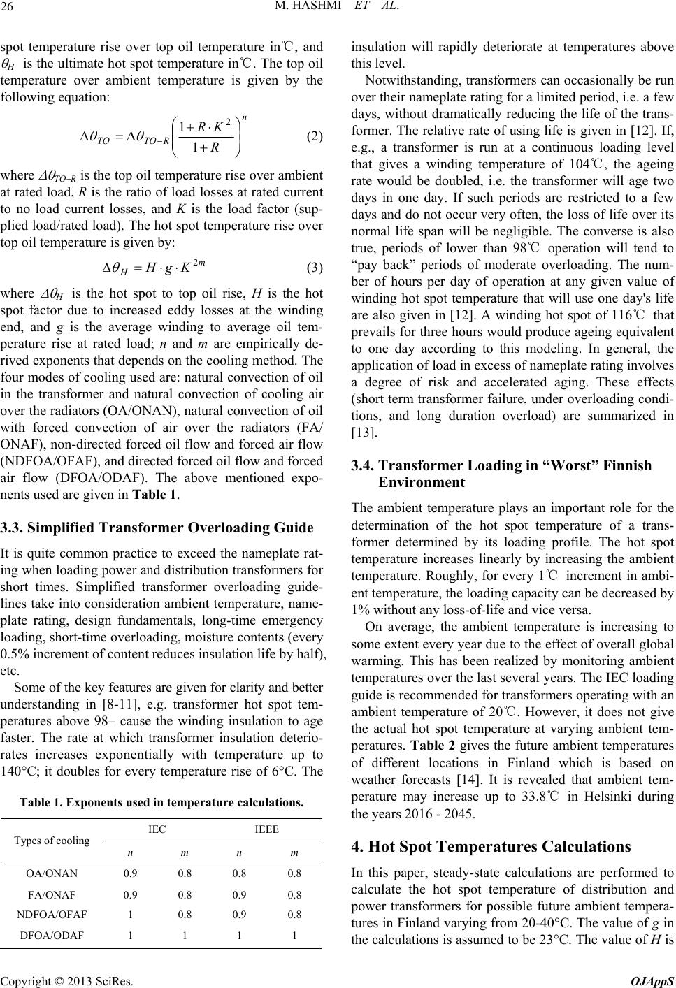 M. HASHMI ET AL. 26 spot temperature rise over top oil temperature in℃, and H is the ultimate hot spot temperature in℃. The top oil temperature over ambient temperature is given by the following equation: n RTOTO R KR 1 12 (2) where TO R is the top oil temperature rise over ambient at rated load, R is the ratio of load losses at rated current to no load current losses, and K is the load factor (sup- plied load/rated load). The hot spot temperature rise over top oil temperature is given by: m HKgH 2 (3) where H is the hot spot to top oil rise, H is the hot spot factor due to increased eddy losses at the winding end, and g is the average winding to average oil tem- perature rise at rated load; n and m are empirically de- rived exponents that depends on the cooling method. The four modes of cooling used are: natural convection of oil in the transformer and natural convection of cooling air over the radiators (OA/ONAN), natural convection of oil with forced convection of air over the radiators (FA/ ONAF), non-directed forced oil flow and forced air flow (NDFOA/OFAF), and directed forced oil flow and forced air flow (DFOA/ODAF). The above mentioned expo- nents used are given in Table 1. 3.3. Simplified Transformer Overloading Guide It is quite common practice to exceed the nameplate rat- ing when loading power and distribution transformers for short times. Simplified transformer overloading guide- lines take into consideration ambient temperature, name- plate rating, design fundamentals, long-time emergency loading, short-time overloading, moisture contents (every 0.5% increment of content reduces insulation life by half), etc. Some of the key features are given for clarity and better understanding in [8-11], e.g. transformer hot spot tem- peratures above 98‒ cause the winding insulation to age faster. The rate at which transformer insulation deterio- rates increases exponentially with temperature up to 140°C; it doubles for every temperature rise of 6°C. The Table 1. Exponents used in temperature calculations. IEC IEEE Types of cooling n m n m OA/ONAN 0.9 0.8 0.8 0.8 FA/ONAF 0.9 0.8 0.9 0.8 NDFOA/OFAF 1 0.8 0.9 0.8 DFOA/ODAF 1 1 1 1 insulation will rapidly deteriorate at temperatures above this level. Notwithstanding, transformers can occasionally be run over their nameplate rating for a limited period, i.e. a few days, without dramatically reducing the life of the trans- former. The relative rate of using life is given in [12]. If, e.g., a transformer is run at a continuous loading level that gives a winding temperature of 104℃, the ageing rate would be doubled, i.e. the transformer will age two days in one day. If such periods are restricted to a few days and do not occur very often, the loss of life over its normal life span will be negligible. The converse is also true, periods of lower than 98℃ operation will tend to “pay back” periods of moderate overloading. The num- ber of hours per day of operation at any given value of winding hot spot temperature that will use one day's life are also given in [12]. A winding hot spot of 116℃ that prevails for three hours would produce ageing equivalent to one day according to this modeling. In general, the application of load in excess of nameplate rating involves a degree of risk and accelerated aging. These effects (short term transformer failure, under overloading condi- tions, and long duration overload) are summarized in [13]. 3.4. Transformer Loading in “Worst” Finnish Environment The ambient temperature plays an important role for the determination of the hot spot temperature of a trans- former determined by its loading profile. The hot spot temperature increases linearly by increasing the ambient temperature. Roughly, for every 1℃ increment in ambi- ent temperature, the loading capacity can be decreased by 1% without any loss-of-life and vice versa. On average, the ambient temperature is increasing to some extent every year due to the effect of overall global warming. This has been realized by monitoring ambient temperatures over the last several years. The IEC loading guide is recommended for transformers operating with an ambient temperature of 20℃. However, it does not give the actual hot spot temperature at varying ambient tem- peratures. Table 2 gives the future ambient temperatures of different locations in Finland which is based on weather forecasts [14]. It is revealed that ambient tem- perature may increase up to 33.8℃ in Helsinki during the years 2016 - 2045. 4. Hot Spot Temperatures Calculations In this paper, steady-state calculations are performed to calculate the hot spot temperature of distribution and power transformers for possible future ambient tempera- tures in Finland varying from 20-40C. The value of g in the calculations is assumed to be 23C. The value of H is Copyright © 2013 SciRes. OJAppS  M. HASHMI ET AL. 27 Table 2. Extreme temperatures for the periods 1961 - 1990 and 2016 - 2045 (ilmatieteen laitos 1991). Extreme temperatures (˚C) 1961 1990 20162045 Helsinki -35.9 31.9 -28.4 33.8 Tampere -37 31.6 -30 33.5 Vaasa -38.6 31.8 -31.6 33.7 Kuopio -39.3 32.6 -32.6 34.6 Kuusamo -45.2 31.2 -39.2 33.1 Sodankylä -44.7 31.3 -38.8 32.9 assumed to be 1.1 for distribution transformers and 1.3 for medium size and large power transformers. The value of TO R is selected in such a fashion (57.8℃ for distri- bution transformers and 54.1℃ for power transformers) that the ultimate hot spot temperature works out to be 98 ℃ for an ambient temperature of 20℃. A 500 kVA transformer having load losses of 5 kW at ambient tem- perature 20℃ and a 20 MVA transformer having load losses of 106 kW at ambient temperature 20℃ are con- sidered for calculations. 4.1. Calculations for Distribution Transformers The data for secondary line transformers is given in Ap- pendix 1 [15]. The values of n and m are taken as 0.9 and 0.8, respectively, for the ONAN mode of cooling. R is defined as the ratio between load losses at rated current to no load losses. The load losses at rated current given by the manufacturer are estimated at an ambient tem- perature of 20℃. However, their value increases due to increase in the resistance of the windings at higher am- bient temperatures. A 0.4% increase in load losses due to a 1℃ rise in ambient temperature is a good approxima- tion for this calculation. The load losses at rated current (given in Appendix 1) also include this incremental fac- tor. For example, the load losses at rated current for a 50 kVA transformer are given as 1330 W at an ambient temperature of 20℃ [15]. The hot spot temperature is to be calculated at 33.8℃ (the projected maximum tem- perature in Helsinki in 2045). The increase in ambient temperature is 13.8℃, which increases the load losses by 73 W. Therefore, the total load losses are estimated to be 1403 W. The value of R is recalculated due to the in- crease in load losses. The rated load of the transformer slightly increases due to increases in load losses (tem- perature dependent) at higher ambient temperatures; therefore, the supplied load is also increased to the same extent for unity load factor conditions (K = 1). For de- termining the actual de-rating factor of the transformers, the calculated value (including the effect of temperature dependent load losses) is divided by the same incre- mental factor. The hot spot temperature for an ambient temperature of 33.8℃ (Helsinki maximum future temperature in 2045) is calculated to be 115℃ for a variety of distribu- tion transformers. Conversely, the transformers should be de-rated to approximately 86% - 87% of their maximum load for a hot spot temperature of 98℃ (as per IEC guide). The value of the hot spot temperature is approximately the same for different ratings of transformers. The ratings of the transformers do not have significant effect on the load factor, i.e. the de-rated values of load factors for distribution transformers are in the same range. 4.2. Calculations for Power Transformers The data for primary line transformers is given in Ap- pendix 2 [15]. The assumptions stated in sub-section 4.1 have also been implemented in the calculations for power transformers. The load losses at rated current (given in Appendix 2) also include the incremental factor ex- plained in sub-section 4.1. For example, the load losses at rated current for a 16 MVA transformer are given as 88 kW at an ambient temperature of 20℃ [13]. The hot spot temperature is to be calculated at 33.8℃ (Helsinki maximum future temperature in 2045). The increase in ambient temperature is 13.8℃ which increases the load losses by 4.9 kW, and so the total load losses are esti- mated to 92.9 kW. The hot spot temperature for an ambient temperature of 33.8℃ (Helsinki's maximum future temperature in 2045) is calculated to be 115℃. Conversely, the trans- formers should be de-rated to approximately 86% - 87% of their maximum load to maintain a hot spot tempera- ture of 98℃ (as per IEC guide). The value of the hot spot temperature is approximately the same for different ratings of transformers. The ratings of the transformers do not have a significant effect on the load factor, i.e. the derated values of load factors for power transformers are in the same range. The different values of hot spot tem- peratures and load factors due to variation in ambient temperature are calculated for distribution and power transformers and are given in Table 3. 5. Results and Discussion The results are extracted from the hot spot temperatures calculations performed in the previous section. It is re- vealed from Figure 2 that by increasing the ambient temperature, the hot spot temperature also increases. This relationship is not quite linear because the temperature dependent winding resistance effects have been taken into account. The rated load losses depend on ambient temperature and this has been considered during the cal- culations. The effect of ambient temperature on the rating Copyright © 2013 SciRes. OJAppS 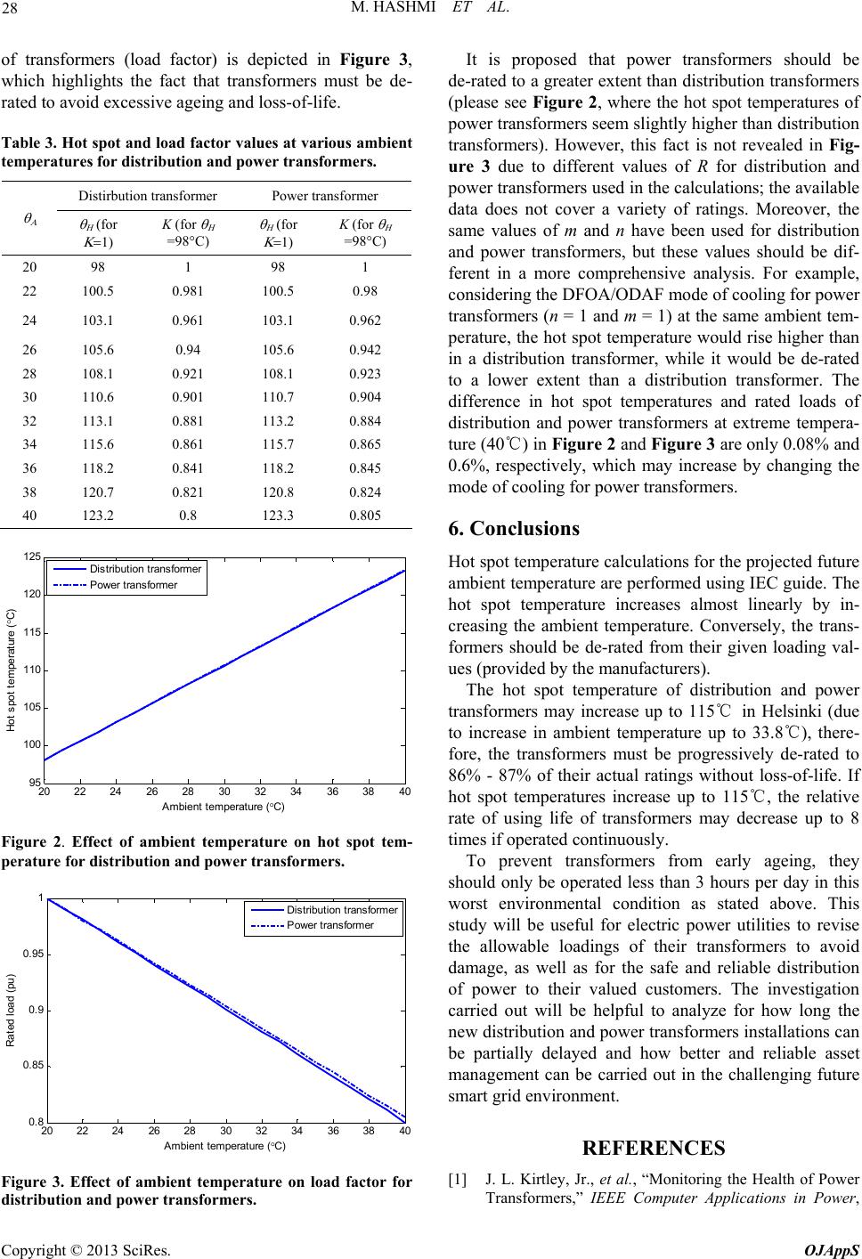 M. HASHMI ET AL. 28 of transformers (load factor) is depicted in Figure 3, which highlights the fact that transformers must be de- rated to avoid excessive ageing and loss-of-life. Table 3. Hot spot and load factor values at various ambient temperatures for distribution and power transformers. Distirbution transformer Power transformer for K (for =98°C) for K (for =98°C) 20 98 1 98 1 22 100.5 0.981 100.5 0.98 24 103.1 0.961 103.1 0.962 26 105.6 0.94 105.6 0.942 28 108.1 0.921 108.1 0.923 30 110.6 0.901 110.7 0.904 32 113.1 0.881 113.2 0.884 34 115.6 0.861 115.7 0.865 36 118.2 0.841 118.2 0.845 38 120.7 0.821 120.8 0.824 40 123.2 0.8 123.3 0.805 20 22 24 2628 3032 34 36 38 40 95 100 105 110 115 120 125 Ambient temperature ( C) Hot spot temperature ( C) Distribution transformer Power transformer Figure 2. Effect of ambient temperature on hot spot tem- perature for distribution and power transformers. 20 2224 26 2830 3234 36 3840 0. 8 0. 85 0. 9 0. 95 1 Ambient temperature ( C) Rated load (pu) Distribution transformer Power transformer Figure 3. Effect of ambient temperature on load factor for distribution and power transformers. It is proposed that power transformers should be de-rated to a greater extent than distribution transformers (please see Figure 2, where the hot spot temperatures of power transformers seem slightly higher than distribution transformers). However, this fact is not revealed in Fig- ure 3 due to different values of R for distribution and power transformers used in the calculations; the available data does not cover a variety of ratings. Moreover, the same values of m and n have been used for distribution and power transformers, but these values should be dif- ferent in a more comprehensive analysis. For example, considering the DFOA/ODAF mode of cooling for power transformers (n = 1 and m = 1) at the same ambient tem- perature, the hot spot temperature would rise higher than in a distribution transformer, while it would be de-rated to a lower extent than a distribution transformer. The difference in hot spot temperatures and rated loads of distribution and power transformers at extreme tempera- ture (40℃) in Figure 2 and Figure 3 are only 0.08% and 0.6%, respectively, which may increase by changing the mode of cooling for power transformers. 6. Conclusions Hot spot temperature calculations for the projected future ambient temperature are performed using IEC guide. The hot spot temperature increases almost linearly by in- creasing the ambient temperature. Conversely, the trans- formers should be de-rated from their given loading val- ues (provided by the manufacturers). The hot spot temperature of distribution and power transformers may increase up to 115℃ in Helsinki (due to increase in ambient temperature up to 33.8℃), there- fore, the transformers must be progressively de-rated to 86% - 87% of their actual ratings without loss-of-life. If hot spot temperatures increase up to 115℃, the relative rate of using life of transformers may decrease up to 8 times if operated continuously. To prevent transformers from early ageing, they should only be operated less than 3 hours per day in this worst environmental condition as stated above. This study will be useful for electric power utilities to revise the allowable loadings of their transformers to avoid damage, as well as for the safe and reliable distribution of power to their valued customers. The investigation carried out will be helpful to analyze for how long the new distribution and power transformers installations can be partially delayed and how better and reliable asset management can be carried out in the challenging future smart grid environment. REFERENCES [1] J. L. Kirtley, Jr., et al., “Monitoring the Health of Power Transformers,” IEEE Computer Applications in Power, Copyright © 2013 SciRes. OJAppS 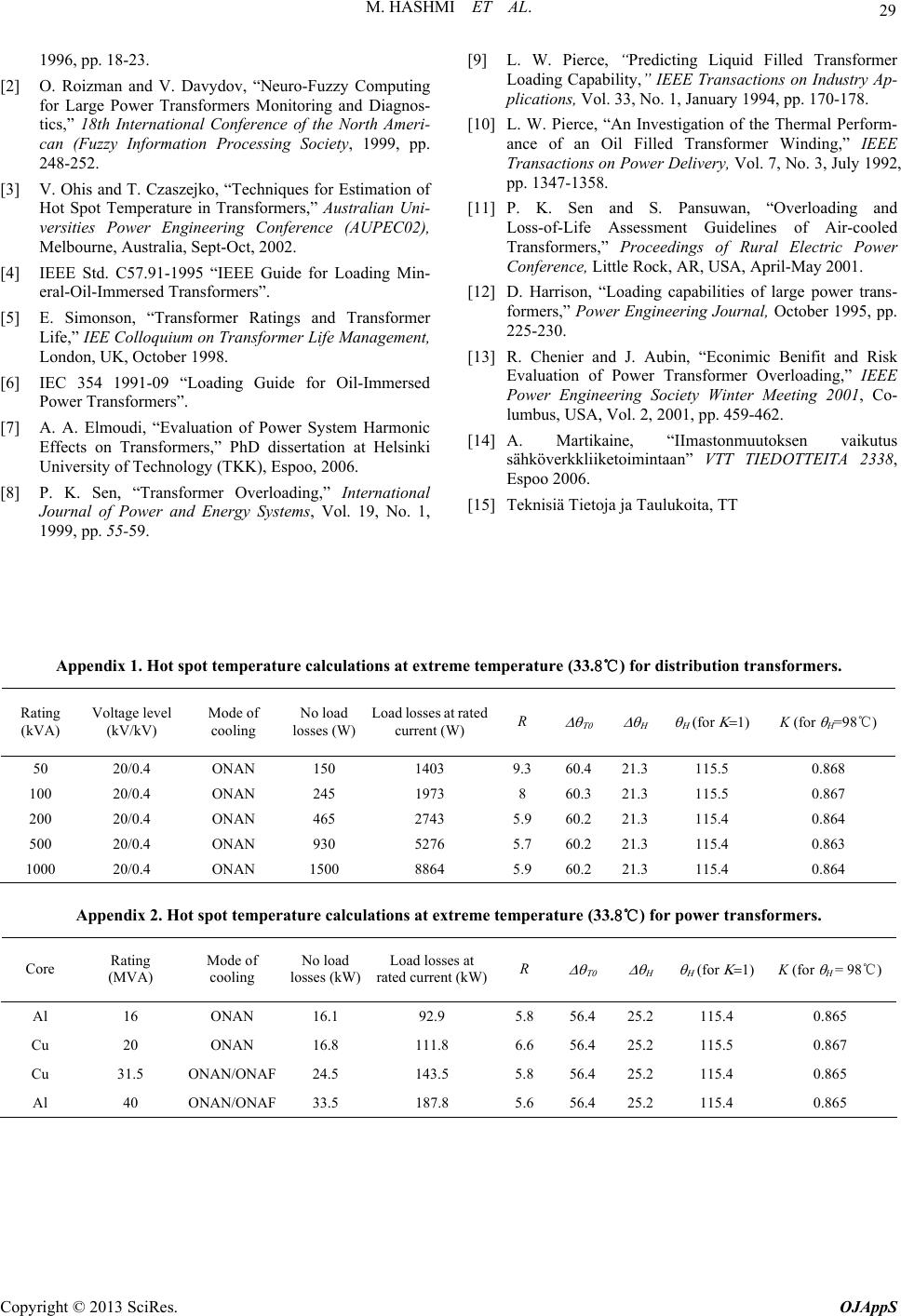 M. HASHMI ET AL. Copyright © 2013 SciRes. OJAppS 29 1996, pp. 18-23. [2] O. Roizman and V. Davydov, “Neuro-Fuzzy Computing for Large Power Transformers Monitoring and Diagnos- tics,” 18th International Conference of the North Ameri- can (Fuzzy Information Processing Society, 1999, pp. 248-252. [3] V. Ohis and T. Czaszejko, “Techniques for Estimation of Hot Spot Temperature in Transformers,” Australian Uni- versities Power Engineering Conference (AUPEC02), Melbourne, Australia, Sept-Oct, 2002. [4] IEEE Std. C57.91-1995 “IEEE Guide for Loading Min- eral-Oil-Immersed Transformers”. [5] E. Simonson, “Transformer Ratings and Transformer Life,” IEE Colloquium on Transformer Life Management, London, UK, October 1998. [6] IEC 354 1991-09 “Loading Guide for Oil-Immersed Power Transformers”. [7] A. A. Elmoudi, “Evaluation of Power System Harmonic Effects on Transformers,” PhD dissertation at Helsinki University of Technology (TKK), Espoo, 2006. [8] P. K. Sen, “Transformer Overloading,” International Journal of Power and Energy Systems, Vol. 19, No. 1, 1999, pp. 55-59. [9] L. W. Pierce, “Predicting Liquid Filled Transformer Loading Capability,” IEEE Transactions on Industry Ap- plications, Vol. 33, No. 1, January 1994, pp. 170-178. [10] L. W. Pierce, “An Investigation of the Thermal Perform- ance of an Oil Filled Transformer Winding,” IEEE Transactions on Power Delivery, Vol. 7, No. 3, July 1992, pp. 1347-1358. [11] P. K. Sen and S. Pansuwan, “Overloading and Loss-of-Life Assessment Guidelines of Air-cooled Transformers,” Proceedings of Rural Electric Power Conference, Little Rock, AR, USA, April-May 2001. [12] D. Harrison, “Loading capabilities of large power trans- formers,” Power Engineering Journal, October 1995, pp. 225-230. [13] R. Chenier and J. Aubin, “Econimic Benifit and Risk Evaluation of Power Transformer Overloading,” IEEE Power Engineering Society Winter Meeting 2001, Co- lumbus, USA, Vol. 2, 2001, pp. 459-462. [14] A. Martikaine, “IImastonmuutoksen vaikutus sähköverkkliiketoimintaan” VTT TIEDOTTEITA 2338, Espoo 2006. [15] Teknisiä Tietoja ja Taulukoita, TT Appendix 1. Hot spot temperature calculations at extreme temperature (33.8℃) for distribution transformers. Rating (kVA) Voltage level (kV/kV) Mode of cooling No load losses (W) Load losses at rated current (W) R for K (for H=98℃) 50 20/0.4 ONAN 150 1403 9.3 60.4 21.3 115.5 0.868 100 20/0.4 ONAN 245 1973 8 60.3 21.3 115.5 0.867 200 20/0.4 ONAN 465 2743 5.9 60.2 21.3 115.4 0.864 500 20/0.4 ONAN 930 5276 5.7 60.2 21.3 115.4 0.863 1000 20/0.4 ONAN 1500 8864 5.9 60.2 21.3 115.4 0.864 Appendix 2. Hot spot temperature calculations at extreme temperature (33.8℃) for power transformers. Core Rating (MVA) Mode of cooling No load losses (kW) Load losses at rated current (kW)R for K (for H = 98℃) Al 16 ONAN 16.1 92.9 5.8 56.4 25.2 115.4 0.865 Cu 20 ONAN 16.8 111.8 6.6 56.4 25.2 115.5 0.867 Cu 31.5 ONAN/ONAF 24.5 143.5 5.8 56.4 25.2 115.4 0.865 Al 40 ONAN/ONAF 33.5 187.8 5.6 56.4 25.2 115.4 0.865 |