Vol.5, No.8A1, 27-37 (2013) Natural Science
http://dx.doi.org/10.4236/ns.2013.58A1004
Comparison of base-isolated liquid storage tank
models under bi-directional earthquakes
Sandip Kumar Saha*, Vasant A. Matsagar, Arvind K. Jain
Department of Civil Engineering, Indian Institute of Technology (IIT) Delhi, New Delhi, India;
*Corresponding Author: sandipksh@civil.iitd.ac.in
Received 13 June 2013; revised 13 July 2013; accepted 20 July 2013
Copyright © 2013 Sandip Kumar Saha et al. This is an open access article distributed under the Creative Commons Attribution Li-
cense, which permits unrestricted use, distribution, and reproduction in any medium, provided the original work is properly cited.
ABSTRACT
Seismic response of ground supported base-
iso la ted liquid storage tanks are evaluated under
bi-directional earthquakes. The base-isolated li-
quid storage tanks are modeled using mecha-
nical analogs with two and three lumped masses
(Model 1 and Model 2). Two types of isolation
systems, such as sliding system and elasto-
meric system, are considered for the present
study. The isolation systems are modeled using
Wen’s equation for hysteretic isolation systems.
Response of base-isolated liquid storage tanks,
evaluated through two different modeling ap-
proaches, is compared. Both the models predict
similar sloshing displacement. The effect of in-
teraction between the mutually perpendicular
seismic responses of the isol ator is inv estigated
for both the models. It is observed that interac-
tion affects the peak seismic response of the
base-isolated liquid storage tanks significantly,
under the bi-directional earthquake components.
Keywords: Base Isolation; Bi-Directional;
Earthquake; Interaction; Liquid; Sloshin g; Tank
1. INTRODUCTION
Liquid storage tanks are one of the many important
structures that demand greater safety measures against
natural disaster like earthquake. Post failure conse-
quences of industrial tanks sometimes trigger greater
impact on human life through fire, chemical contamina-
tion, nuclear radiation etc. Besides these, water storage
tanks are required to be maintained functional to serve
the society even after devastating earthquake. Hence,
protection of liquid storage tanks against earthquake is
very essential. The dynamic behavior of liquid contain-
ing structures cannot be estimated by the same approach
as for normal building structure, since the inside liquid
influences its behavior largely. Therefore, appropriate
modeling of the liquid storage tanks is essential for dy-
namic analysis and seismic response evaluation. Several
research works reported in literature and guidelines in
international codes and specifications are available for
seismic analysis and design of liquid storage tanks [1-4].
Most of the design guidelines follow the lumped mass
mechanical analog to model the cylindrical liquid storage
tanks. A brief review of the international codes on seis-
mic analysis of liquid storage tanks can be found in [5].
However, conventional design approach, without sophis-
ticated vibration control devices, many times cannot pro-
vide sufficient protection against seismic forces.
Several researchers have reported the benefits of the
passive vibration control strategy using base isolation
technique, as an efficient seismic protection method of
structures [6-9]. There are two broad categories of base
isolation systems, which are in use throughout the world,
such as sliding system and elastomeric bearing. Malhotra
[10], Shrimali and Jangid [11] and many other research-
ers reported the use of base isolation for enhancing seis-
mic performance of liquid storage tanks. Shrimali and
Jangid [12] investigated the effect of seismic response
interaction on the performance of base-isolated liquid
storage tanks. However, they had only considered the
sliding bearing as isolation system. Jadhav and Jangid
[13] compared the performance of different isolation
systems for seismic protection of liquid storage tanks.
They had investigated the performance of liquid storage
tanks under bi-directional near-fault earthquake. How-
ever, the effect of the interaction between the orthogonal
hysteretic responses of the isolators was not studied.
In most of the above research works, the base-isolated
liquid storage tank has been modeled using the me-
chanical analog proposed by Haroun and Housner [14].
This model considers the tank wall flexibility while cal-
culating the seismic response. Another mechanical ana-
log, proposed earlier by Housner [4], is also extensively
Copyright © 2013 SciRes. OPEN ACCESS
S. K. Saha et al. / Natural Science 5 (2013) 27-37
28
used for modeling of liquid storage tanks for dynamic
analysis. The major difference of these two models is the
number of lumped masses into which the liquid column
is divided. Whereas, the two-mass model is convenient
for designers to use due to ease, the three-mass model
apparently predicts the seismic response more accurately.
Hence, the choice of an appropriate modeling approach
is crucial.
Herein, the base-isolated liquid storage tank is mo-
deled using both, the two- and three mass models and the
interaction of isolator hysteretic response is investigated
under bi-directional earthquakes. Two different types of
isolation systems, namely sliding system and elastomeric
bearing, are considered for the present study. The major
objectives of this study are: 1) to compare the seismic
response using two different lumped mass models of
base-isolated liquid storage tanks subjected to bi-direc-
tional earthquakes; and 2) to investigate the effect of in-
teraction between the two mutually perpendicular hys-
teretic displacement components of isolation system.
2. MODELING OF BASE-ISOLATED
LIQUID STORAGE TANKS
The ground supported cylindrical base-isolated liquid
storage tank is modeled using two different lumped mass
mechanical analogs: 1) two-mass model (Model 1) pro-
posed by Housner [4] and 2) three-mass model (Model 2)
proposed by Haroun and Housner [14]. Figure 1 shows
the two different models of the base-isolated liquid
storage tanks. A brief detail of the models are provided
here.
2.1. Two-Mass Model (Model 1)
This model divides the liquid column into two layers.
The upper layer, called convective mass, is considered to
vibrate relative to the tank wall and resulting in the
sloshing phenomenon, whereas the bottom layer, called
impulsive mass, vibrates with the tank as rigid body and
experience same earthquake acceleration as the base. The
impulsive mass predominately contributes to the base
shear and overturning moment of the tank. In this model,
the convective mass (mc) of the liquid is considered to be
connected to the solid tank wall with certain stiffness (kc)
at a height Hc, whereas the impulsive mass (mi) is con-
nected rigidly to the tank wall at a height Hi. In the pre-
sent study, only tanks with circular plan geometry are
considered; hence, hereafter all the discussion will be
restricted to circular tank only.
Figure 1(a) shows the schematic diagram of the tank
model with the parameters mentioned above where total
height of the liquid inside the tank is denoted by H and
radius for circular tank is denoted by R.
The stiffness of the spring attached to the convective
mass (kc) as per this model is given by
1.84tanh1.84
cc
kmgR H
R
(1)
where, g is the gravitational acceleration. Detailed ex-
pressions for the other parameters of the tank model are
given in [4].
2.2. Three-Mass Model (Model 2)
In this model, Haroun and Housner [14] proposed an
additional rigid mass (mr), acting at a height of Hr, that
rigidly moves along with the tank wall. The impulsive
mass (mi), acting at a height of Hi, is assumed in contact
with the tank wall through a spring with stiffness ki.
Similarly, the convective or sloshing mass (mc), acting at
a height of Hc, is assumed in contact with the tank wall
through a spring with stiffness kc. They also considered a
Figure 1. Schematic diagrams of the base-isolated liquid storage tanks: (a) Two-mass model (Model 1) and
(b) Three-mass model (Model 2).
Copyright © 2013 SciRes. OPEN ACCESS
S. K. Saha et al. / Natural Science 5 (2013) 27-37 29
small amount of damping, for impulsive and sloshing mass.
Figure 1(b) shows the schematic diagram of Model 2
with all the parameters. The stiffness of the springs at-
tached to the convective mass (kc) is same as the Model 1;
however, the stiffness of the spring attached to the im-
pulsive mass (ki) is given by

2
iis
kEm PH
(2)
where, E and ρs are the modulus of elasticity and density
of the tank wall material, respectively; and P is a dimen-
sionless parameter. The parameters of the tank are given
in graphical form in [14]. The mathematical expressions
of the parameters can be obtained from [11].
3. MODELING OF ISOLATION SYSTEM
For the present study, a non-linear model [15] is used
to characterize the hysteretic force-deformation behavior
of the isolation system, as shown in Figure 2. The behavior
of the isolator is considered identical in both x-and y-
directions. The restoring forces developed in these isola-
tion systems for bi-directional excitation are given by

01
0
x
bx eb
y
by
y
b
e
Z
FkxF
F
Z
y
k


 

 

 

 


 
(3)
where, Fy denotes yield strengths of the bearing in both
x- and y-directions; α represents the ratio of post to
pre-yield stiffness; ke denotes pre-yield stiffness of the
bearing in both x- and y-directions. Here, Zx and Zy de-
note non-dimensional hysteretic displacement compo-
nents satisfying the following non-linear first order dif-
ferential equation [16].
11 12
21 22
x
b
y
b
Z
x
CC
q
Z
y
CC
 


 





 (4)
where,

1
11 sgn nn
bxx
CAxZZ Z
x
 
,

1
12 sgn n
byx x
CyZZ

 
y
ZZ,

1
21 sgn n
byy yx

CxZZZZ

 
,
and 1
22 sgn nn
byy y
CAyZZZ
 
.
In Eq.4, q denotes isolator yield displacement in both
x- and y-directions; A,
and τ are dimensionless pa-
rameters; and parameter n is an integer constant, which
controls smoothness of the transition from elastic to plas-
tic response. These dimensionless parameters A,
, τ and
n can be chosen in such a way that the model represents
either a sliding system or an elastomeric system.
4. EQUATIONS OF MOTION
The governing equations of motion of the base-iso-
lated liquid storage tank under bi-directional earthquake
excitation are written in the matrix form as
 

g
M
XCXKXF Mru

 

 

 
(5)
Figure 2. Non-linear
Force-deformation beha-
vior of the isolation sys-
tem.
where, {X} is the relative displacement vector; {F} is the
hysteretic restoring force vector;
M


, C
and
K
are the mass, damping and stiffness matrices of the
system, respectively;
 
T
ggxgy
uuu
  is the earth-
quake ground acceleration vector and [r] is the influence
coefficient matrix. The order of the vectors and matrices
depend on the model of the liquid storage tank.
For Model 1, the mass matrix,
M


, damping matrix,
C
and stiffness matrix,
K


can be written as
00
00
00
00
cc
c
cc
c
mm
mM
Mmm
mM


(6)
diag cbcb
Cccc

 c (7)
diag cbcb
K
kkkk

 (8)
where, M = mc + mi. The displacement and hysteretic
restoring vectors are given as

T
cb cb
X
xxyy (9)
 
T
01 01
yx yy
FFZF

 Z (10)
where, xc = (ucx ubx) and y
c = (ucy uby) are the dis-
placements of the convective mass relative to the bearing
displacement in x- and y-directions, respectively; x
b =
(ubx ugx) and y
b = (uby ugy) are bearing displacements
relative to the ground in x- and y-directions, respectively.
The influence coefficient matrix takes the following form

T
0100
0001
r
(11)
For Model 2, the mass,
M


, damping, C
and
stiffness,
K
matrices are given as
0 000
000
000
000 0
000 0
000
cc
ii
ci
cc
ii
ci
mm
mm
mmM
Mmm
mm
mmM
0


(12)
Copyright © 2013 SciRes. OPEN ACCESS
S. K. Saha et al. / Natural Science 5 (2013) 27-37
30
diag cibcib
Cccccc

 c (13)
diag cibcib
K
kkkkkk

 (14)
where, M = mc + mi + mb. The displacement and hyster-
etic restoring vectors are given as

T
cibcib
X
xxxyyy (15)
  
T
00 100 1
yx yy
FFZ

 
FZ
(16)
where, xc = (ucx ubx) and y
c = (ucy uby) are the dis-
placements of the convective mass relative to the bearing
displacement in x- and y-directions, respectively; xi = (uix
ubx) and yi = (uiy uby) are the displacements of the im-
pulsive mass relative to the bearing displacements in x-
and y-directions, respectively; xb = (ubx ugx) and yb = (uby
ugy) are bearing displacements relative to the ground in
x- and y-directions, respectively. The influence coeffi-
cient matrix takes the following form

T
001000
000001
r


(17)
Numerical solution of Eq.5 is obtain using Newmark’s
step-by-step integration technique, adopting linear varia-
tion of acceleration between two time steps, to determine
the seismic response of the base-isolated liquid storage
tank. Once the displacement and acceleration quantities
are known, for Model 2, the base shears (Vbx and Vby) and
overturning moments (Mbx and Mby) in either direction
are
bxc cxi ixr bx
Vmumumu (18)
byc cyi iyr by
Vmumumu (19)
bxc cxi ixir bxr
M
mumu HmuH  (20)
byc cyi iyirbyr
M
mumu HmuH  (21)
For Model 1, appropriate masses, accelerations and
heights are to be taken for the calculation of the base
shear and overturning moment.
5. NUMERICAL STUDIES
Ground supported cylindrical steel storage tanks are
considered for the present study. Two different tank con-
figurations are taken namely broad and slender. In Table
1, the geometrical properties of the cylindrical steel tanks
are summarized. The thickness of the tank wall, used for
Model 2, is denoted by t. The slenderness ratio (S) is
determined by
H
R. The liquid inside the tank is con-
sidered as water (mass density = 1000 kg/m3). For Model
2, the damping of the convective (ξc) and impulsive (ξi)
masses are assumed as 0.5% and 2%, respectively. In the
present study, two different types of the isolators are
studied, such as sliding system and elastomeric bearing.
To model isolator force-deformation behavior, the di-
mensionless parameters of the Wen’s model are chosen
appropriately as given in Table 2. Total eight earthquake
time histories, comprising of near-fault and far-fault
ground motions, are considered. The details of the earth-
quake acceleration inputs are given in Table 3. The slid-
ing system is characterized by the isolation time period
(Tb) and friction coefficient (µ). Whereas, the elas-
tomeric bearing is commonly characterized by its isola-
tion time period (Tb) and damping (ξb), yield displace-
ment (q) and the normalized yield strength (y
F
W),
where, W = Mg is the total weight of the structure. For
the present study, Tb and µ for the sliding system is as-
sumed as 2 sec and 0.05, respectively. The elastomeric
bearing properties are assumed as, Tb = 2 sec, ξb = 0.1
and y
F
W = 0.05.
The isolator force-deformation for the sliding system
and elastomeric bearing are plotted in Figure 3 for
El-Centro earthquake. Model 1 represents the two mass
mechanical analog, whereas Model 2 represents three
mass mechanical analog. The isolator restoring forces
(Fbx and Fby) are presented in normalized form in terms
of the total weight of the structure (W). It is observed that
the Wen’s model can represent the force-deformation
behavior of two different types of isolators, when the
parameters are chosen appropriately.
5.1 Comparison of Seismic Response
Obtained from Two Models
The peak seismic response quantities of base-isolated
liquid storage tanks using the two models are compared
herein. The important seismic response quantities con-
sidered are the base shears (Vbx and Vby), base displace-
ments (xb and yb), sloshing displacements (xc and yc) and
overturning moments (Mbx and Mby). For the sliding sys-
tem, the isolation time period (Tb) is taken as 2 sec and
the friction coefficient (µ) is taken as 0.05. The isolation
time period (Tb), the isolation damping (ξb) and the nor-
malized yield strength (y
F
W) of the elastomeric bear-
ing are taken as 2 sec, 0.1 and 0.05, respectively. Two
types of tank configurations, such as broad (S = 0.6) and
Table 1. Properties of the cylindrical tanks.
Type of tank SHR H (m) tR
Broad tank 0.6 14.6 0.004
Slender tank 1.85 11.3 0.004
Table 2. Parameters of the Wen’s model.
Isolator Aβ τ n q (cm)
Sliding system 1 0.9 0.1 2 0.025
Elastomeric bearing 1 0.5 0.5 2 2.5
Copyright © 2013 SciRes. OPEN ACCESS
S. K. Saha et al. / Natural Science 5 (2013) 27-37
Copyright © 2013 SciRes.
31
Table 3. Details of the earthquake acceleration time histories.
Sl. no. Event; record Notation Component Direction PGAa (g)
Normal (N) x 0.26
1 Imperial Valley, 1940; El-Centro El-Centro Parallel (P) y 0.31
Normal (N) x 0.36
2 Imperial Valley, 1979; Array#5 Imperial
#5 Parallel (P) y 0.54
Normal (N) x 0.45
3 Imperial Valley, 1979; Array#7 Imperial
#7 Parallel (P) y 0.33
Normal (N) x 0.61
4 Loma Prieta, 1989; LGPC Loma Prieta Parallel (P) y 0.56
Normal (N) x 0.87
5 Northridge, 1992; Rinaldi Rinaldi Parallel (P) y 0.38
Normal (N) x 0.72
6 Northridge, 1992; Sylmar Sylmar Parallel (P) y 0.58
Normal (N) x 0.71
7 Landers, 1992; Lucerne Valley Lucerne Parallel (P) y 0.64
Normal (N) x 0.60
8 Kobe, 1995; JMA Kobe Parallel (P) y 0.2 8
aPGA = Peak ground acceleration.
Figure 3. Isolator force-deformation behavior under El-Centro earthquake (for sliding system: Tb = 2 sec and µ
= 0.05; for elastomeric bearing: Tb = 2 sec, ξb = 0.1, q = 2.5 cm, y
FW = 0.05).
slender (S = 1.85), are studied. Figures 4 and 5 show the
response time histories under El-Centro earthquake for
the broad and slender tank configurations in x- and y-
directions, respectively. The hear and the overturn- base s
OPEN ACCE SS
S. K. Saha et al. / Natural Science 5 (2013) 27-37
32
Figure 4. Time history of the response quantities along x- direction under bi-directional El-Centro earthquake.
Figure 5. Time history of the response quantities along y-direction under bi-directional El-Centro earthquake.
ing moments are presented as normalized with respect to
total weight of the structure (W).
It can be observed that there are considerable differ-
ences in the seismic response obtained by the two dif-
ferent modeling approaches for the liquid storage tanks.
However, the sloshing displacement is not much affected
by the modeling approaches. This phenomenon is also
evident from Eq.1. The sloshing frequency is not influ-
Copyright © 2013 SciRes. OPEN ACCESS
S. K. Saha et al. / Natural Science 5 (2013) 27-37 33
Table 4. Peak seismic response quantities of base-isolated liquid storage tanks (for sliding system: Tb = 2 sec and µ = 0.05; for elastomeric bearing: Tb = 2 sec, ξb = 0.1, q = 2.5
cm, Fy/W = 0.05).
Copyright © 2013 SciRes. OPEN ACCESS
S. K. Saha et al. / Natural Science 5 (2013) 27-37
34
Continued
Copyright © 2013 SciRes. OPEN ACCESS
S. K. Saha et al. / Natural Science 5 (2013) 27-37
Copyright © 2013 SciRes.
35
Figure 6. Effect of seismic response interaction on broad tank (for sliding system: Tb = 2 sec and µ = 0.05; for elastomeric
bearing: Tb = 2 sec, ξb = 0.1, q = 2.5 cm, y
FW = 0.05).
Figure 7. Effect of seismic response interaction on slender tank (for sliding system: Tb = 2 sec and µ = 0.05; for elastomeric
bearing: Tb = 2 sec, ξb = 0.1, q = 2.5 cm, y
FW = 0.05).
isolated by sliding system, contains significant high fre-
quency response, which is also observed for building like
structure [17].
enced by the material properties of the tank wall, and
they are the same for both the tank models. Hence, their
seismic response time histories are also not affected by
the modeling approaches. However, with the inclusion of
an additional rigid mass the impulsive frequency changes
in Model 2. As a result, the base shear, base displacement
and overturning moment differ with the modeling ap-
proaches. It is further observed that the computed base
shear and overturning moment of the liquid storage tank,
The peak seismic response quantities of the broad and
slender tanks are compared in Ta ble 4 for all the earth-
quakes given in Table 3. It can be observed that the
Model 1 underestimate the peak seismic response of the
base-isolated liquid storage tanks. However, peak slosh-
ing displacements, computed using the two different
OPEN ACCE SS
S. K. Saha et al. / Natural Science 5 (2013) 27-37
36
modeling approaches, are not affected for both the tank
configurations. Furthermore, the difference in the seismic
response, obtained through two different modeling ap-
proaches, is more for broad tanks as compared to slender
tanks. It can also be observed that most of the seismic
response quantities are increased when the tank is base-
isolated using sliding system as compared to case when
the tank is base-isolated using elastomeric bearing, ex-
cept the base displacements (xb and yb).
5.2 Effect of Interaction on the Peak
Seismic Response
The effect of interaction between two mutually per-
pendicular hysteretic displacement components of the
isolator under bi-directional earthquake excitation is
studied. For the sliding system, the isolation time period
(Tb) is taken as 2 sec and the friction coefficient (µ) is
taken as 0.05. The isolation time period (Tb), the isolation
damping (ξb) and the normalized yield strength (y
F
W)
of the elastomeric bearing are taken as 2 sec, 0.1 and
0.05, respectively. Two types of tank configurations, such
as broad (S = 0.6) and slender (S = 1.85), are studied.
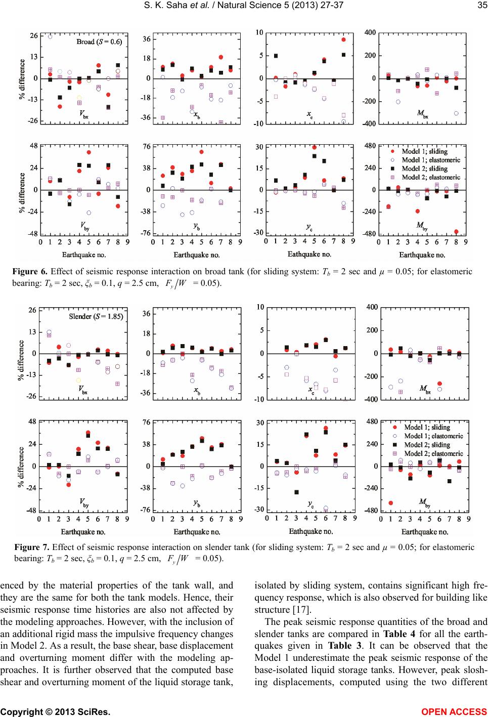
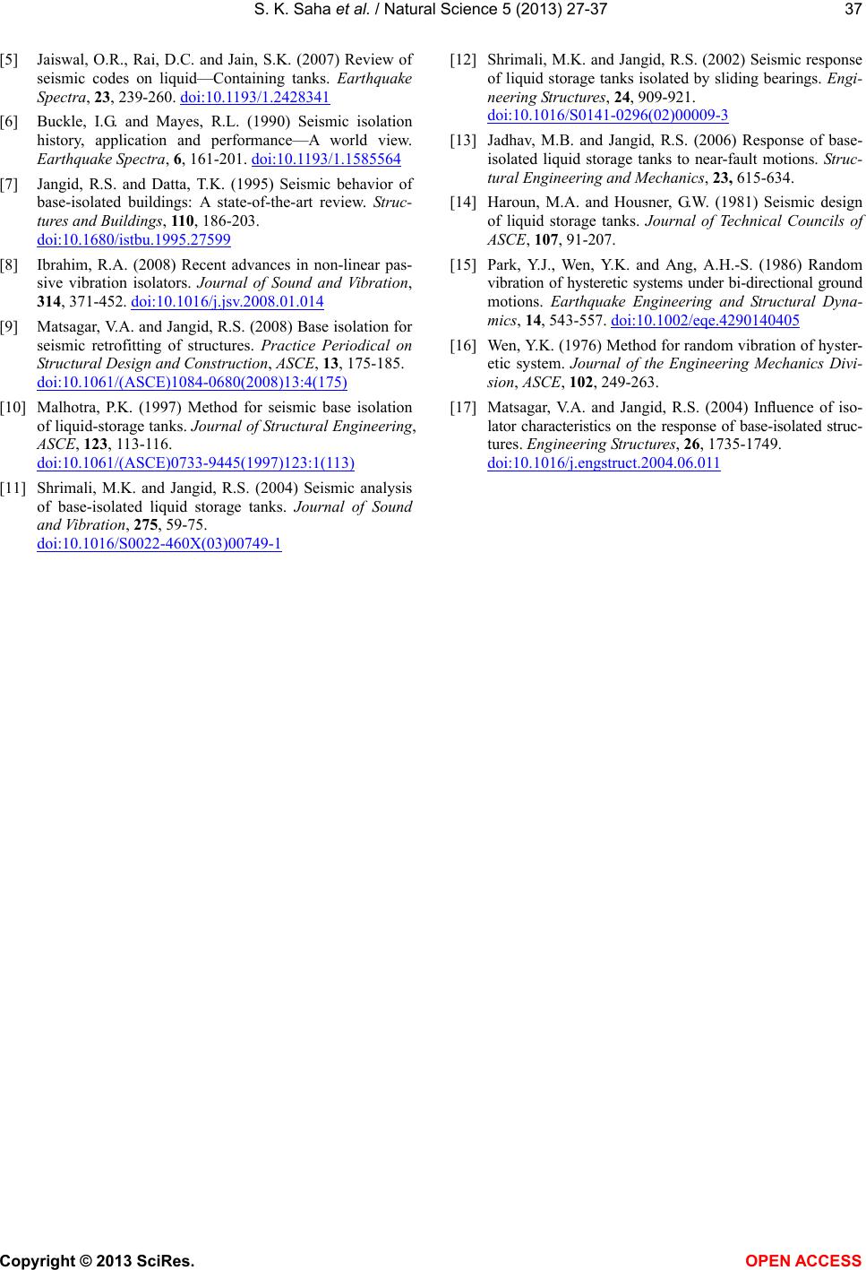
Figures 6 and 7 show the percentage difference of the
peak seismic response quantities for broad and slender
tank configurations, respectively. For example, % dif-
ference in the base displacement in x-direction (xb) is
calculated as
 

interaction no-interaction
interaction
% difference in100
bb
b
b
xx
xx

(22)
where, and

indicates the peak

interaction
b
xno-interaction
b
x
base displacement when interaction is considered and not
considered, respectively. Here, zero percentage indicates
that there is no effect of interaction on the seismic re-
sponse. A negative percentage indicates that the peak
seismic response is more when response interaction is
not considered.
It is observed that both the models of the base-isolated
liquid storage tanks are showing similar trend to predict
the effect of response interaction of broad and slender
tanks. It is also observed that the effect of interaction is
most significant for base displacement. Sloshing dis-
placement is less affected by the interaction. Base shear
and overturning moment are also influenced by the con-
sideration of the interaction. The effect of the interaction
in bi-directional seismic response is observed to be mar-
ginally more in the broad tanks as compared to the slen-
der tanks, and the seismic response along y- direction is
more influenced by the interaction than along x-direc-
tion. It is further observed that the consideration of the
interaction affect the seismic response differently in case
of sliding system and elastomeric bearing. The effect of
interaction in case of the sliding system is more pro-
nounced than in case of the elastomeric bearing. For
sliding system, the base displacement increases when the
interaction is considered. However, for elastomeric bear-
ing interaction reduces the base displacement.
6. CONCLUSIONS
Seismic response of base-isolated liquid storage tanks
is investigated under bi-directional earthquakes. The liq-
uid storage tank is modeled using a) two mass and b)
three mass mechanical analogs. Two different isolation
systems, namely sliding system and elastomeric bearing,
are considered. A comparison of the important response
quantities, obtained through two different modeling ap-
proaches of the tank, is carried out. The effects of the
interaction, between the two mutually perpendicular
hysteretic displacement components of the isolator, on
the response, are also studied. Following are the major
conclusions drawn from the present study.
1) The two-mass model (Model 1) and three-mass
model (Model 2) of the base-isolated liquid storage tanks
estimate almost the same sloshing displacement. How-
ever, base shear, base displacement and overturning
moment are underestimated by the two-mass model as
compared to the three-mass model.
2) The base shear and overturning moment of the liquid
storage tank, isolated by sliding system, contains signifi-
cant high frequency components.
3) The difference in the peak response, obtained
through Model 1 and Model 2, is more for broad tanks.
4) Peak seismic response quantities, except base dis-
placements, are increased when the tank is base-isolated
using sliding system as compared to case when the tank
is base-isolated using elastomeric bearing.
5) Consideration of interaction between two mutually
perpendicular hysteretic displacement components of the
isolator significantly affects the peak response of the
base-isolated liquid storage tanks.
6) Effect of the interaction under bi-directional earth-
quake is predicted similarly by the Model 1 and Model 2.
REFERENCES
[1] ACI 350.3 (2006) Seismic design of liquid containing
concrete structures. American Concrete Institute, Farm-
ington Hills.
[2] API 650 (1998) Welded storage tanks for oil storage.
American Petroleum Institute Standard, Washington DC.
[3] AWWA D-100 (1996) Welded steel tanks for water stor-
age. American Water Works Association, Colorado.
[4] Housner, G.W. (1963) The dynamic behavior of water
tanks. Bulletin of Seismological Society of America, 53,
381-387.
Copyright © 2013 SciRes. OPEN ACCESS
S. K. Saha et al. / Natural Science 5 (2013) 27-37
Copyright © 2013 SciRes. OPEN ACCESS
37
[5] Jaiswal, O.R., Rai, D.C. and Jain, S.K. (2007) Review of
seismic codes on liquid—Containing tanks. Earthquake
Spectra, 23, 239-260. doi:10.1193/1.2428341
[6] Buckle, I.G. and Mayes, R.L. (1990) Seismic isolation
history, application and performance—A world view.
Earthquake Spectra, 6, 161-201. doi:10.1193/1.1585564
[7] Jangid, R.S. and Datta, T.K. (1995) Seismic behavior of
base-isolated buildings: A state-of-the-art review. Struc-
tures and Buildings, 110, 186-203.
doi:10.1680/istbu.1995.27599
[8] Ibrahim, R.A. (2008) Recent advances in non-linear pas-
sive vibration isolators. Journal of Sound and Vibration,
314, 371-452. doi:10.1016/j.jsv.2008.01.014
[9] Matsagar, V.A. and Jangid, R.S. (2008) Base isolation for
seismic retrofitting of structures. Practice Periodical on
Structural Design and Construction, ASCE, 13, 175-185.
doi:10.1061/(ASCE)1084-0680(2008)13:4(175)
[10] Malhotra, P.K. (1997) Method for seismic base isolation
of liquid-storage tanks. Journal of Structural Engineering,
ASCE, 123, 113-116.
doi:10.1061/(ASCE)0733-9445(1997)123:1(113)
[11] Shrimali, M.K. and Jangid, R.S. (2004) Seismic analysis
of base-isolated liquid storage tanks. Journal of Sound
and Vibration, 275, 59-75.
doi:10.1016/S0022-460X(03)00749-1
[12] Shrimali, M.K. and Jangid, R.S. (2002) Seismic response
of liquid storage tanks isolated by sliding bearings. Engi-
neering Structures, 24, 909-921.
doi:10.1016/S0141-0296(02)00009-3
[13] Jadhav, M.B. and Jangid, R.S. (2006) Response of base-
isolated liquid storage tanks to near-fault motions. Struc-
tural Engineering and Mechanics, 23, 615-634.
[14] Haroun, M.A. and Housner, G.W. (1981) Seismic design
of liquid storage tanks. Journal of Technical Councils of
ASCE, 107, 91-207.
[15] Park, Y.J., Wen, Y.K. and Ang, A.H.-S. (1986) Random
vibration of hysteretic systems under bi-directional ground
motions. Earthquake Engineering and Structural Dyna-
mics, 14, 543-557. doi:10.1002/eqe.4290140405
[16] Wen, Y.K. (1976) Method for random vibration of hyster-
etic system. Journal of the Engineering Mechanics Divi-
sion, ASCE, 102, 249-263.
[17] Matsagar, V.A. and Jangid, R.S. (2004) Inuence of iso-
lator characteristics on the response of base-isolated struc-
tures. Engineering Structures, 26, 1735-1749.
doi:10.1016/j.engstruct.2004.06.011