Paper Menu >>
Journal Menu >>
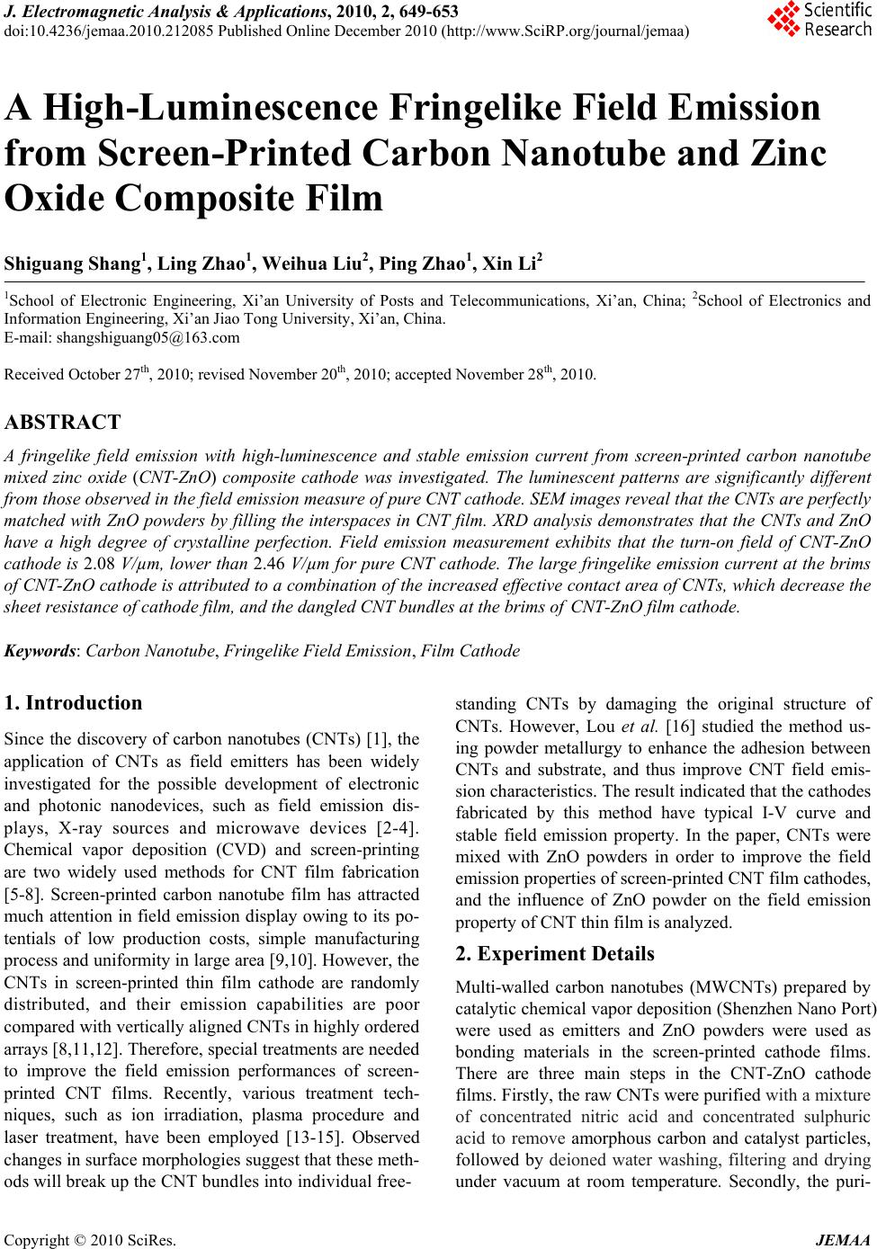 J. Electromagnetic Analysis & Applications, 2010, 2, 649-653 doi:10.4236/jemaa.2010.212085 Published Online December 2010 (http://www.SciRP.org/journal/jemaa) Copyright © 2010 SciRes. JEMAA A High-Luminescence Fringelike Field Emission from Screen-Printed Carbon Nanotube and Zinc Oxide Composite Film Shiguang Shang1, Ling Zhao1, Weihua Liu2, Ping Zhao1, Xin Li2 1School of Electronic Engineering, Xi’an University of Posts and Telecommunications, Xi’an, China; 2School of Electronics and Information Engineering, Xi’an Jiao Tong University, Xi’an, China. E-mail: shangshiguang05@163.com Received October 27th, 2010; revised November 20th, 2010; accepted November 28th, 2010. ABSTRACT A fringelike field emission with high-luminescence and stable emission current from screen-printed carbon nanotube mixed zinc oxide (CNT-ZnO) composite cathode was investigated. The luminescent patterns are significantly different from those observed in the field emission measure of pure CNT cathode. SEM images reveal that the CNTs are perfectly matched with ZnO powders by filling the interspaces in CNT film. XRD analysis demonstrates that the CNTs and ZnO have a high degree of crystalline perfection. Field emission measurement exhibits that the turn-on field of CNT-ZnO cathode is 2.08 V/µm, lower than 2.46 V/µm for pure CNT cathode. The large fringelike emission current at th e brims of CNT-ZnO catho de is attributed to a combination of the in creased effective contact area of CNTs, which decrease the sheet resistance of cathode film, and the dangled CNT bundles at th e brims of CNT-ZnO film cathode. Keywords: Carbon Nanotube, Fringelike Field Emission, Film Cathode 1. Introduction Since the discovery of carbon nanotubes (CNTs) [1], the application of CNTs as field emitters has been widely investigated for the possible development of electronic and photonic nanodevices, such as field emission dis- plays, X-ray sources and microwave devices [2-4]. Chemical vapor deposition (CVD) and screen-printing are two widely used methods for CNT film fabrication [5-8]. Screen-printed carbon nanotube film has attracted much attention in field emission display owing to its po- tentials of low production costs, simple manufacturing process and uniformity in large area [9,10]. However, the CNTs in screen-printed thin film cathode are randomly distributed, and their emission capabilities are poor compared with vertically aligned CNTs in high ly ordered arrays [8,11,12]. Therefore, special treatments are needed to improve the field emission performances of screen- printed CNT films. Recently, various treatment tech- niques, such as ion irradiation, plasma procedure and laser treatment, have been employed [13-15]. Observed changes in surface morphologies suggest that these meth- ods will break up th e C N T bundles into individual free- standing CNTs by damaging the original structure of CNTs. However, Lou et al. [16] studied the method us- ing powder metallurgy to enhance the adhesion between CNTs and substrate, and thus improve CNT field emis- sion characteristics. The result indicated that the cathodes fabricated by this method have typical I-V curve and stable field emission property. In the paper, CNTs were mixed with ZnO powders in order to improve the field emission properties of screen-printed CNT film cathodes, and the influence of ZnO powder on the field emission property of CNT thin film is analyzed. 2. Experiment Details Multi-walled carbon nanotubes (MWCNTs) prepared by catalytic chemical vapor deposition (Shenzhen Nano Port) were used as emitters and ZnO powders were used as bonding materials in the screen-printed cathode films. There are three main steps in the CNT-ZnO cathode films. Firstly, the raw CNTs were purified with a mixture of concentrated nitric acid and concentrated sulphuric acid to remove amorphous carbon and catalyst particles, followed by deioned water washing, filtering and drying under vacuum at room temperature. Secondly, the puri-  A High-Luminescence Fringelike Field Emission from Screen-Printed Carbon Nanotube and Zinc Oxide Composite Film 650 fied CNTs were dispersed into terpineol by ultrasonica- tion for a long time, followed by filtration to remove the large particles. Then ethyl cellulose was mixed with the solution by stirring and heating it up to120°C until ethyl cellulose was fully dissolved. Then we got pure CNTs paste for screen-printing. Following the same procedure, we got the ZnO powder paste. Finally, the two pastes were mixed (50 wt%: 50 wt %) and screen-printed onto silver coated glass substrates. After being lift in clean room for 24 hours, the CNT-ZnO film cathodes were sintered at 596°C for 60 minutes in argon to remove the organic binder. The surface morphologies of the pure CNT and CNT-ZnO films were characterized by field emission scanning electron microscopy (FESEM, JSM-6700F, Japan). The structural information of CNT-ZnO film was analyzed by small angle X-ray diffraction in Shimadzu diffractometer (XRD-6000, Japan) using Cu Ka radiation. The field emission characteristics were tested with a pla- nar diode configuration. The distance between cathode and anode was fixed at 200 μm and the emission area was 1 2 cm2. The measurements were carried out at room temperature in a vacuum chamber at 10-6 Pa base pressure. 3. Results and Discussion Figures 1(a-c) show the SEM images of pure CNT and CNT-ZnO screen-printed film cathodes after sintering. As shown in Figure 1(a), the pure CNT film shows a homogeneous and clean surface, where the CNTs were loose and randomly oriented. Figure 1(b) shows the morphology of the CNT-ZnO film cathode. The CNTs and ZnO powder formed a continuous conductive layer and the film show some roughness with island of CNT-ZnO agglomerations. On the assumption that the protruded tips and/or arcs of CNTs were potential emit- ters, the emitter density of CNT-ZnO film was decreased and only the protuberances of CNTs were formed the field emission tips. However, the roots of CNTs were embedded into ZnO agglomeration, which would give a significant improvement of the electrical contact of CNTs to the substrate. Figure 1(c) shows the cross-sec- tion view of the CNT-ZnO film cathode. The pure CNTs film is a layer of loose network on the substrate. While, in the CNTs-ZnO composite film, ZnO grains geometri- cally matched with CNTs by filling into the interspaces of CNTs or directly covering upon CNTs, thus few pro- truding CNT emitters on the surface of CNT-ZnO com- posite film were obtained. Nevertheless, many dangle bundles are observed on the cross-section of CNT-ZnO film cathode, which can deduce that there are many po- tential emitters at both of the brims of CNT-ZnO com- posite film. (a) (b) (c) Figure 1. Scanning electron microscopy images of screen- printing CNT cathode films: (a) Pure CNT film, (b) CNT- ZnO film and (c) Cross-section of CNT-ZnO film. Copyright © 2010 SciRes. J EMAA  A High-Luminescence Fringelike Field Emission from Screen-Printed Carbon Nanotube and Zinc Oxide Composite Film 651 Figure 2 shows the XRD patterns obtained from theCNT-ZnO composite film. To avoid the appearance of silver diffraction peaks, the CNT-ZnO paste was printed onto glass substrates directly. As shown in the XRD pat- tern, the curve is pertinent to the diffraction peaks both from hexagonal wurtzite structure zinc oxide and graph- ite structure CNTs. The dominant peaks of hexagonal wurtzite structure zinc oxide are at 2θ = 31.7, 34.3, 36.2 and 56.5, corresponding to (100), (002), (101) and (110) crystal orientations, respectively. Three representative peaks of graphite structure at 2θ = 26.0, 42.6 and 54.7, corresponding to (022), (100) and (004) crystal orientations, are also observed. The XRD peaks of CNTs are narrower and sharper than that of the untreated sam- ples [17], indicating that the crystallinity of the CNTs was improved. The main reasons are contributed to re- move of carbonaceous particles, such as fullerenes, nanoparticles and amorphous phases at high sintering. The high crystallinity is beneficial for field emission [4,18]. Figures 3(a,b) show the lighting images of pure CNT and CNT-ZnO film cathode. Figure 3(a) is the typical field emission pattern of the pure CNT film at applied voltage of 1.26 kV, in which the emission sites were sporadic and nonuniform. Figure 3(b) is the field emis- sion pattern of the CNT-ZnO film at applied voltage of 1.12 kV. As shown in Figure 3(b), the emission sites were located at both brims of the CNT-ZnO films, and the luminescence areas stretches outwards from the brims of CNT-ZnO film cathode. The luminescence areas show a fringelike shape, and which are similar to the contrails of pendulum in simple harmonic motion. During the field emission of the CNT-ZnO films, the luminescence areas would change from a uniform and static pattern to an unstable flash one with the increas ing of applie d voltage. Figure 2. X-ray diffraction patterns of CNT-ZnO composite film. (a) (b) Figure 3. Field emission images of screen-printing cathode films: (a) Pure CNT film, (b) CNT-ZnO composite film. The main reason was supposed to be the electron-wave interferences. The electron-wave interference may be generated from the coherent transport properties of the neighbor CNT emission sites in CNT-ZnO dangled bun- dles, which were in good agreement with the emission pattern from Pt field emitter fabricated by electron- beam-induced deposition [19]. Generally, the vibration amplitude corresponding to low applied voltage is too small to detect. Further work is needed to explore the fundamental physics. For the CNT-ZnO composite film cathode, we believe that the fringelike field emission is closely related with several facts. Firstly, the interspaces of CNTs were filled with ZnO grains and the CNT-ZnO film was formed a good conductiv e layer. The conductiv e bonding materials would result in low sheet resistance of screen-printed films so that the penetration of the electrical field can be ignored, leading to th e low field enhancement factor [20]. Copyright © 2010 SciRes. JEMAA  A High-Luminescence Fringelike Field Emission from Screen-Printed Carbon Nanotube and Zinc Oxide Composite Film 652 Secondly, some CNT-ZnO agglomerations island, as shown in Figures 1(b,c), are higher than surface CNT emitters on CNT-ZnO film cathode, and thus suppressed the field enhancement effects of emission sites. Thirdly, the CNTs at the brims of the CNT-ZnO film cathode are easier to form dangled bundles, and the screening effect on the CNTs near the brims is lower than that on the sur- face CNTs of CNT-ZnO film. In addition, low contact resistance can be formed from silver electrode to CNT emitters. Therefore, the CNT emitters at the brims of CNT-ZnO film cathode would have good emission prop- erty and high saturation current density. As a result, the fringelike luminescence pattern was formed. Figure 4 shows the field emission current densities of pure CNT and CNT-ZnO films as a function of applied voltage. The turn-on electric fields (defined as the elec- tric field when the emission current density reaches 10 µA/cm2) of the pure CNT and the CNT-ZnO films are 2.46 V/ µm and 2.08 V/ µm, respectively. Compared to the pure CNT film cathode, the CNT-ZnO film cathode has lower turn-on electric field and higher field emission current density. The results indicate that the mixing of CNT and ZnO powder can enhance the field emission ability of CNTs. It is mainly contributed to the formation of high contact area and low contact resistance between CNTs and substrate. Therefore, the barrier on the junc- tion of CNTs to substrate would be eliminated, and elec- trons can pass through this jun ction without ob stacle [21]. During the whole field emission, electrons only need to overcome CNT-vacuum barrier, a low voltage would result in a considerable electron emission. The emission degradation behavior of emission current density was also measured. After 200 minutes operation with initial emission current density of 200 µA/ cm2, current degen- eration of CNT-ZnO film cathode less than 5% were ob- served. The results indicated that the field emission of CNT-ZnO film cathode was stable. Figure 4. Field emission I-V curves of different screen- printing CNT films: (a) pure CNT film, (b) CNT-ZnO com- posite film. 4. Conclusions A composite film cathode of CNT-ZnO was fabricated to improve the field emission performances of CNT emit- ters, and a high-luminescence fringelike field emission was observed. The experiment results indicate the CNT-ZnO film cathode has three characteristics as fol- lowing. Firstly, most of the emission sites showing high intensity emission locate at both brims of the CNT-ZnO composite film. And small part of emission sites locate at the center of cathode film, which has lower field emis- sion capability than that of pure CNTs. Secondly, field emission electrons from neighboring emitters at the brims of CNT-ZnO cathode film maybe generate elec- tron-wave interferences, and which would cause dynamic field emission pattern. Finally, the fringelike field emis- sion of CNT-ZnO film cathode exhibits lower turn-on field, higher luminescence intensity and excellent emis- sion current stability. In a summary, the CNT-ZnO film provides a promising cold cathode for lighting sources, such as field emission lighting tube and back light. 5. Acknowledgements The work was financially supported from the grant from the 863-Programme of the Ministry of Science and Technology of China (No. 2008AA03A314), and Xi’an Applied Materials Innovation Fund Application No. XA-AM-201004. REFERENCES [1] S. Iijima, “Helical Microtubes of Graphite Carbon,” Na- ture, Vol. 354, No. 7, 1991, pp. 56-58. [2] J. H. Lee, S. H. Lee, W. S. Kim, H. J. Lee, J. N. Heo, T. W. Jeong, C. H. Choi, J. M. Kim, J. H. Park and J. S. Ha, “Uniformity Measurement of Electron Emission from Carbon Nanotubes Using Electron-Beam Resist,” Journal of Vacuum Science & Technology B, Vol. 23, No. 2, 2005, pp. 718-722. [3] H. Y. Choi, W. S. Chang, H. S. Kim, Y. H. Park and J. U. Kim, “Acquisition of X-Ray Images by Using a CNT Cold Emitter,” Physics Letters A, Vol. 357, No. 1, 2006, pp. 36-41. [4] S. Demoustier, E. Minoux, M. Le Baillif, M. Charles and A. Ziaei, “Review of Two Microwave Applications of Carbon Nanotubes: Nano-Antennas and Nano-Switches,” Comptes Rendus Physique, Vol. 9, No. 1, 2008, pp. 53-66. [5] H. Gao, C. Mu, F. Wang, D. Xu, K. Wu, Y. Xie, S. Liu, E. Wang, J. Xu and D. Yu., “Field Emission of Large-Area and Graphitized Carbon Nanotube Array on Anodic Alu- minum Oxide Template,” Journal of Applied Physics, Vol. 93, No. 9, 2003, pp. 5602-5605. [6] J. Li, W. Lei, X. Zhang, X. Zhou, Q. Wang, Y. Zhang and B. Wang, “Field Emission Characteristic of Screen- Copyright © 2010 SciRes. JEMAA  A High-Luminescence Fringelike Field Emission from Screen-Printed Carbon Nanotube and Zinc Oxide Composite Film Copyright © 2010 SciRes. JEMAA 653 Printed Carbon Nanotube Cathode,” Applied Surface Sci- ence, Vol. 220. No. 1-4, 2003, pp. 96-104. [7] X. H. Liu, C. C. Zhu, W. H. Liu, F. G. Zeng and C. H. Tian, “Large-Area Carbon Nanotubes Film Synthesized for Field Emission Display by Special Cvd Equipment and the Field Emission Properties,” Materials Chemistry and Physics, Vol. 93, No. 2-3, 2005, pp. 473-477. [8] Y. S. Shi, C. C. Zhu, Q. K. Wang and X. Li, “Large Area Screen-Printing Cathode of CNT for FED”, Diamond and Related Materials, Vol. 12, 2003, pp. 1449-1452. [9] Y. S. Choi, Y. S. Cho, J. H. Kang, Y. J. Kim, I. H. Kim, S. H. Park, H.W. Lee, S.Y. Hwang, S. J. Lee and C. G. Lee, “A Field-Emission Display with a Self-Focus Cathode Electrode,” Applied Physics Letter, Vol. 82, No. 20, 2003, pp. 3565-3567. [10] T. J. Vink, M. Gillies, J. C. Kriege and H. Van de Laar, “Enhanced Field Emission from Printed Carbon Nano- tubes by Mechanical Surface Modification,” Applied Physics Letter, Vol. 83, No. 17, 2003, p. 3552. [11] J. T. L. Thong, C. H. Oon, W. K. Eng, W. D. Zhang and L. M. Gan, “High-Current Field Emission from a Verti- cally Aligned Carbon Nanotube Field Emitter Array,” Applied Physics Letter, Vol. 79, No. 17, 2001, p. 2811. [12] J. S. Suh, K. S. Jeong, J. S. Lee and I. Han, “Study of the Field-Screening Effect of Highly Ordered Carbon Nano- tube Arrays,” Applied Physics Letter, Vol. 80, No. 13, 2002, p. 2392. [13] D. H. Kim, C. D. Kim and H. R. Lee, “Effects of the Ion Irradiation of Screen-Printed Carbon Nanotubes for Use in Field Emission Display Applications,” Carbon, Vol. 42, No. 8-9, 2004, pp. 1807-1812. [14] Y. Kanazawa, T. Oyama, K. Murakami and M. Takai, “Chemical Vapor Deposition-Formed P-Type ZnO Thin Films,” Journal of Vacuum Science & Technology B, Vol. 22, 2004, p. 1342. [15] A. Hosono, T. Shiroishi, K. Nishimura, F. Abe, Z. Shen, S. Nakata and S. Okuda, “Emission Characteristics of Printed Carbon Nanotube Cathodes after Laser Treat- ment,” Journal of Vacuum Science & Technology B, Vol. 24, No. 3, 2006, pp. 1423-1427. [16] C. Lou, X. Zhang, W. Lei and C. Qi, “New Method to Fabricate Field-Emission Cathode of Carbon Nanotubes,” Applied Surface Science, Vol. 251, No. 1-4, 2005, pp. 254-257. [17] S. G. Shang, C. C. Zhu and W. H. Liu, “Enhanced Field Emission from Printed CNT by High-Temperature Sin- tering and Plasma Bombarding in Hydrogen,” Microelec- tronics Journal, Vol. 39, No. 1, 2008, pp. 85-89. [18] A. P. Burden, R. D. Forrest and S. R. P. Silva, “Enhanc- ing the Field Emission Properties of Amorphous Carbon Films by Thermal Annealing,” Thin Solid Films, Vol. 337, No. 1-2, 1999, pp. 257-260. [19] K. Murakami, S. Nishihara, N. Matsubara, S. Ichikawa, F. Wakaya and M. Takai, “Superposition of Fringe- like-Electron-Emission Pattern from Radical-Oxy- gen- Gas Exposed Pt Field Emitter Fabricated by Electron- Beam-Induced Deposition,” Journal of Vacuum Science & Technology B, Vol. 27, No. 2, 2009, pp. 721-724. [20] H. Y. Shin, W. S. Chung, K. H. Kim, Y. R. Cho and B. C. Shin, “Effects of Bonding Materials in Screen-Printing Paste on the Field-Emission Properties of Carbon Nano- tube Cathodes,” Journal of Vacuum Science & Technol- ogy B, Vol. 23, No. 6, 2005, pp. 2369-2371. [21] J. Zhang, X. Wang, W. Yang, W. Yu, T. Feng, Q. Li, X. Liu and C. Yang, “Interaction between Carbon Nanotubes and Substrate and Its Implication on Field Emission Mechanism,” Carbon, Vol. 44, No. 3, 2006, pp. 418-422. |