Paper Menu >>
Journal Menu >>
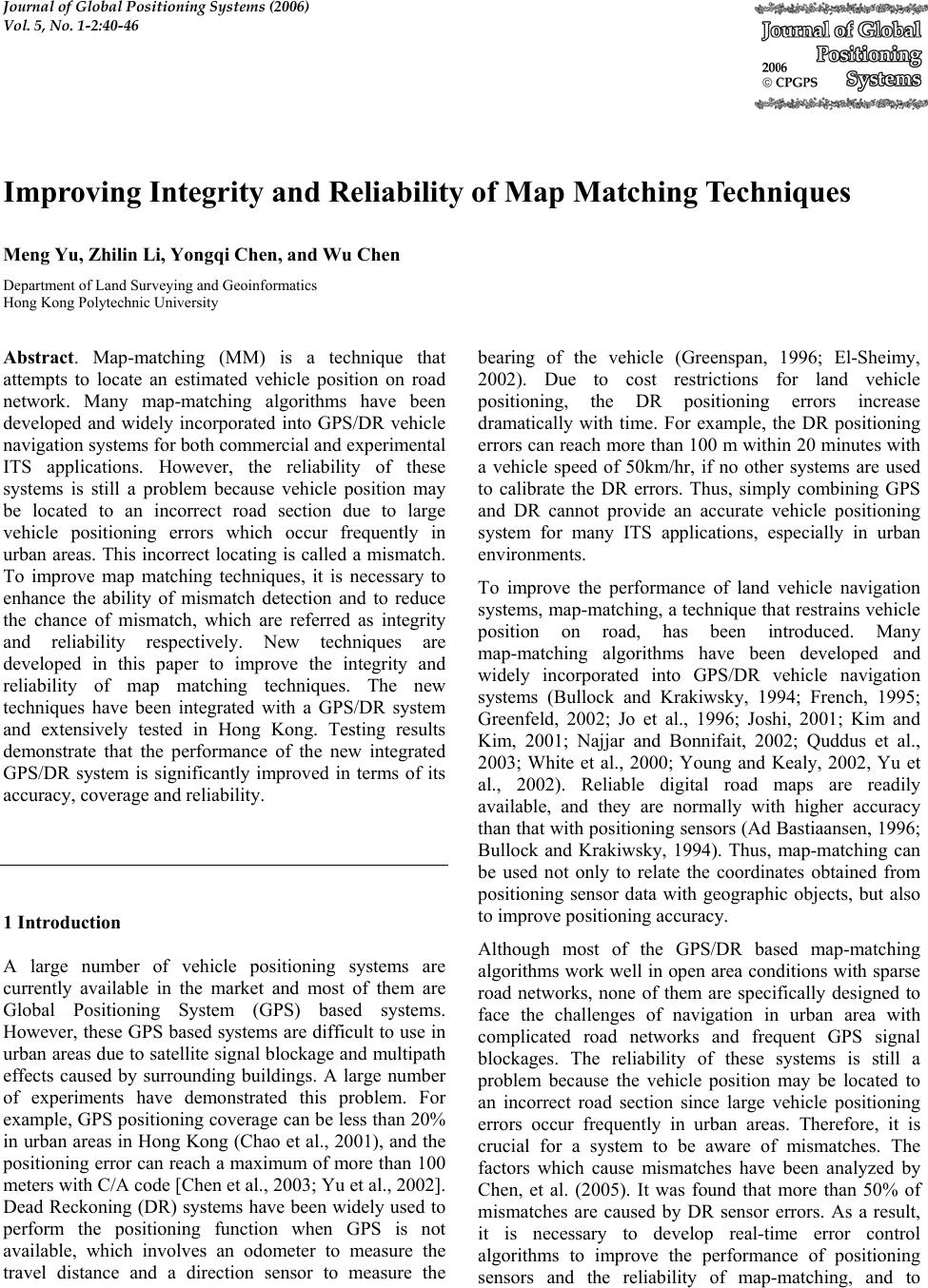 Journal of Global Positioning Systems (2006) Vol. 5, No. 1-2:40-46 Improving Integrity and Reliability of Map Matching Techniques Meng Yu, Zhilin Li, Yongqi Chen, and Wu Chen Department of Land Surveying and Geoinformatics Hong Kong Polytechnic University Abstract. Map-matching (MM) is a technique that attempts to locate an estimated vehicle position on road network. Many map-matching algorithms have been developed and widely incorporated into GPS/DR vehicle navigation systems for both commercial and experimental ITS applications. However, the reliability of these systems is still a problem because vehicle position may be located to an incorrect road section due to large vehicle positioning errors which occur frequently in urban areas. This incorrect locating is called a mismatch. To improve map matching techniques, it is necessary to enhance the ability of mismatch detection and to reduce the chance of mismatch, which are referred as integrity and reliability respectively. New techniques are developed in this paper to improve the integrity and reliability of map matching techniques. The new techniques have been integrated with a GPS/DR system and extensively tested in Hong Kong. Testing results demonstrate that the performance of the new integrated GPS/DR system is significantly improved in terms of its accuracy, coverage and reliability. 1 Introduction A large number of vehicle positioning systems are currently available in the market and most of them are Global Positioning System (GPS) based systems. However, these GPS based systems are difficult to use in urban areas due to satellite signal blockage and multipath effects caused by surrounding buildings. A large number of experiments have demonstrated this problem. For example, GPS positioning coverage can be less than 20% in urban areas in Hong Kong (Chao et al., 2001), and the positioning error can reach a maximum of more than 100 meters with C/A code [Chen et al., 2003; Yu et al., 2002]. Dead Reckoning (DR) systems have been widely used to perform the positioning function when GPS is not available, which involves an odometer to measure the travel distance and a direction sensor to measure the bearing of the vehicle (Greenspan, 1996; El-Sheimy, 2002). Due to cost restrictions for land vehicle positioning, the DR positioning errors increase dramatically with time. For example, the DR positioning errors can reach more than 100 m within 20 minutes with a vehicle speed of 50km/hr, if no other systems are used to calibrate the DR errors. Thus, simply combining GPS and DR cannot provide an accurate vehicle positioning system for many ITS applications, especially in urban environments. To improve the performance of land vehicle navigation systems, map-matching, a technique that restrains vehicle position on road, has been introduced. Many map-matching algorithms have been developed and widely incorporated into GPS/DR vehicle navigation systems (Bullock and Krakiwsky, 1994; French, 1995; Greenfeld, 2002; Jo et al., 1996; Joshi, 2001; Kim and Kim, 2001; Najjar and Bonnifait, 2002; Quddus et al., 2003; White et al., 2000; Young and Kealy, 2002, Yu et al., 2002). Reliable digital road maps are readily available, and they are normally with higher accuracy than that with positioning sensors (Ad Bastiaansen, 1996; Bullock and Krakiwsky, 1994). Thus, map-matching can be used not only to relate the coordinates obtained from positioning sensor data with geographic objects, but also to improve positioning accuracy. Although most of the GPS/DR based map-matching algorithms work well in open area conditions with sparse road networks, none of them are specifically designed to face the challenges of navigation in urban area with complicated road networks and frequent GPS signal blockages. The reliability of these systems is still a problem because the vehicle position may be located to an incorrect road section since large vehicle positioning errors occur frequently in urban areas. Therefore, it is crucial for a system to be aware of mismatches. The factors which cause mismatches have been analyzed by Chen, et al. (2005). It was found that more than 50% of mismatches are caused by DR sensor errors. As a result, it is necessary to develop real-time error control algorithms to improve the performance of positioning sensors and the reliability of map-matching, and to 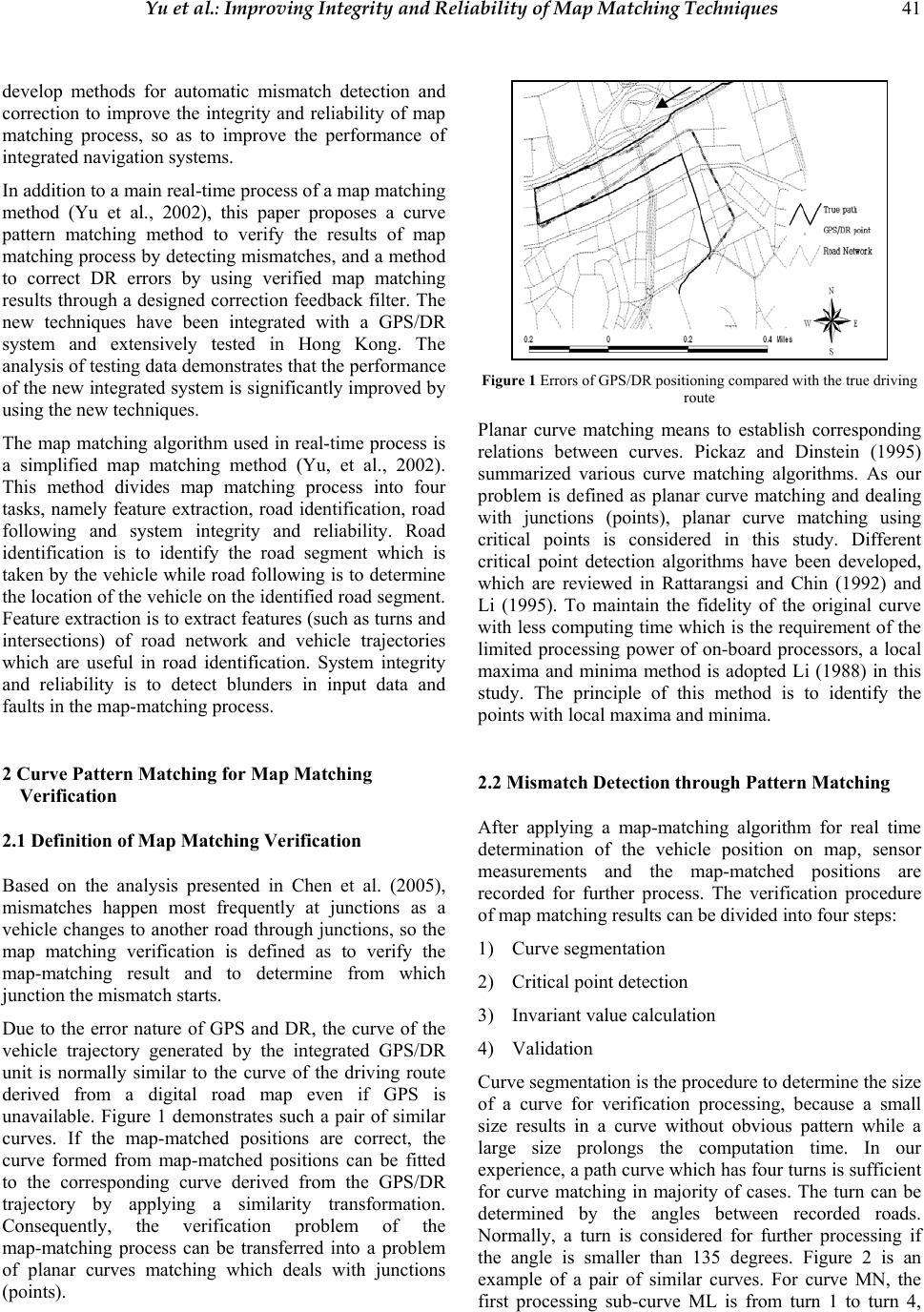 Yu et al.: Improving Integrity and Reliability of Map Matching Techniques 41 develop methods for automatic mismatch detection and correction to improve the integrity and reliability of map matching process, so as to improve the performance of integrated navigation systems. In addition to a main real-time process of a map matching method (Yu et al., 2002), this paper proposes a curve pattern matching method to verify the results of map matching process by detecting mismatches, and a method to correct DR errors by using verified map matching results through a designed correction feedback filter. The new techniques have been integrated with a GPS/DR system and extensively tested in Hong Kong. The analysis of testing data demonstrates that the performance of the new integrated system is significantly improved by using the new techniques. The map matching algorithm used in real-time process is a simplified map matching method (Yu, et al., 2002). This method divides map matching process into four tasks, namely feature extraction, road identification, road following and system integrity and reliability. Road identification is to identify the road segment which is taken by the vehicle while road following is to determine the location of the vehicle on the identified road segment. Feature extraction is to extract features (such as turns and intersections) of road network and vehicle trajectories which are useful in road identification. System integrity and reliability is to detect blunders in input data and faults in the map-matching process. 2 Curve Pattern Matching for Map Matching Verification 2.1 Definition of Map Matching Verification Based on the analysis presented in Chen et al. (2005), mismatches happen most frequently at junctions as a vehicle changes to another road through junctions, so the map matching verification is defined as to verify the map-matching result and to determine from which junction the mismatch starts. Due to the error nature of GPS and DR, the curve of the vehicle trajectory generated by the integrated GPS/DR unit is normally similar to the curve of the driving route derived from a digital road map even if GPS is unavailable. Figure 1 demonstrates such a pair of similar curves. If the map-matched positions are correct, the curve formed from map-matched positions can be fitted to the corresponding curve derived from the GPS/DR trajectory by applying a similarity transformation. Consequently, the verification problem of the map-matching process can be transferred into a problem of planar curves matching which deals with junctions (points). Figure 1 Errors of GPS/DR positioning compared with the true driving route Planar curve matching means to establish corresponding relations between curves. Pickaz and Dinstein (1995) summarized various curve matching algorithms. As our problem is defined as planar curve matching and dealing with junctions (points), planar curve matching using critical points is considered in this study. Different critical point detection algorithms have been developed, which are reviewed in Rattarangsi and Chin (1992) and Li (1995). To maintain the fidelity of the original curve with less computing time which is the requirement of the limited processing power of on-board processors, a local maxima and minima method is adopted Li (1988) in this study. The principle of this method is to identify the points with local maxima and minima. 2.2 Mismatch Detection through Pattern Matching After applying a map-matching algorithm for real time determination of the vehicle position on map, sensor measurements and the map-matched positions are recorded for further process. The verification procedure of map matching results can be divided into four steps: 1) Curve segmentation 2) Critical point detection 3) Invariant value calculation 4) Validation Curve segmentation is the procedure to determine the size of a curve for verification processing, because a small size results in a curve without obvious pattern while a large size prolongs the computation time. In our experience, a path curve which has four turns is sufficient for curve matching in majority of cases. The turn can be determined by the angles between recorded roads. Normally, a turn is considered for further processing if the angle is smaller than 135 degrees. Figure 2 is an example of a pair of similar curves. For curve MN, the first processing sub-curve ML is from turn 1 to turn 4, 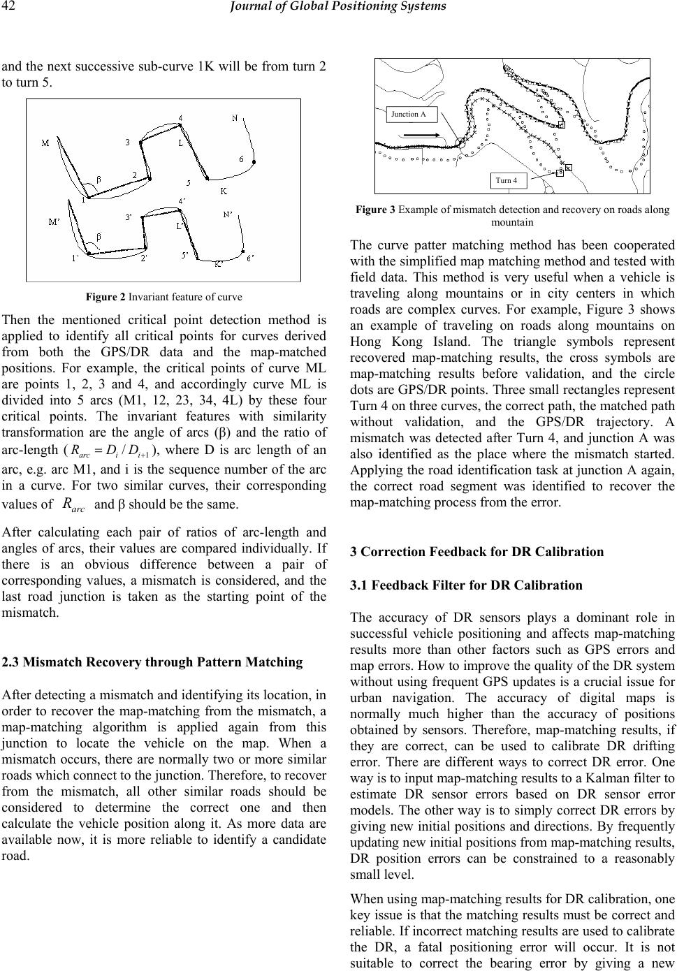 42 Journal of Global Positioning Systems and the next successive sub-curve 1K will be from turn 2 to turn 5. Figure 2 Invariant feature of curve Then the mentioned critical point detection method is applied to identify all critical points for curves derived from both the GPS/DR data and the map-matched positions. For example, the critical points of curve ML are points 1, 2, 3 and 4, and accordingly curve ML is divided into 5 arcs (M1, 12, 23, 34, 4L) by these four critical points. The invariant features with similarity transformation are the angle of arcs (β) and the ratio of arc-length (1 / arci i RDD + =), where D is arc length of an arc, e.g. arc M1, and i is the sequence number of the arc in a curve. For two similar curves, their corresponding values of arc R and β should be the same. After calculating each pair of ratios of arc-length and angles of arcs, their values are compared individually. If there is an obvious difference between a pair of corresponding values, a mismatch is considered, and the last road junction is taken as the starting point of the mismatch. 2.3 Mismatch Recovery through Pattern Matching After detecting a mismatch and identifying its location, in order to recover the map-matching from the mismatch, a map-matching algorithm is applied again from this junction to locate the vehicle on the map. When a mismatch occurs, there are normally two or more similar roads which connect to the junction. Therefore, to recover from the mismatch, all other similar roads should be considered to determine the correct one and then calculate the vehicle position along it. As more data are available now, it is more reliable to identify a candidate road. Figure 3 Example of mismatch detection and recovery on roads along mountain The curve patter matching method has been cooperated with the simplified map matching method and tested with field data. This method is very useful when a vehicle is traveling along mountains or in city centers in which roads are complex curves. For example, Figure 3 shows an example of traveling on roads along mountains on Hong Kong Island. The triangle symbols represent recovered map-matching results, the cross symbols are map-matching results before validation, and the circle dots are GPS/DR points. Three small rectangles represent Turn 4 on three curves, the correct path, the matched path without validation, and the GPS/DR trajectory. A mismatch was detected after Turn 4, and junction A was also identified as the place where the mismatch started. Applying the road identification task at junction A again, the correct road segment was identified to recover the map-matching process from the error. 3 Correction Feedback for DR Calibration 3.1 Feedback Filter for DR Calibration The accuracy of DR sensors plays a dominant role in successful vehicle positioning and affects map-matching results more than other factors such as GPS errors and map errors. How to improve the quality of the DR system without using frequent GPS updates is a crucial issue for urban navigation. The accuracy of digital maps is normally much higher than the accuracy of positions obtained by sensors. Therefore, map-matching results, if they are correct, can be used to calibrate DR drifting error. There are different ways to correct DR error. One way is to input map-matching results to a Kalman filter to estimate DR sensor errors based on DR sensor error models. The other way is to simply correct DR errors by giving new initial positions and directions. By frequently updating new initial positions from map-matching results, DR position errors can be constrained to a reasonably small level. When using map-matching results for DR calibration, one key issue is that the matching results must be correct and reliable. If incorrect matching results are used to calibrate the DR, a fatal positioning error will occur. It is not suitable to correct the bearing error by giving a new Turn 4 Junction A Turn 4 Junction A 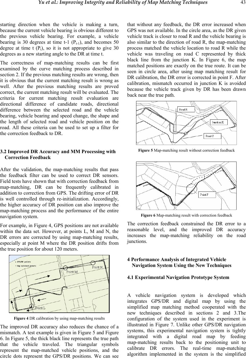 Yu et al.: Improving Integrity and Reliability of Map Matching Techniques 43 starting direction when the vehicle is making a turn, because the current vehicle bearing is obvious different to the previous vehicle bearing. For example, a vehicle bearing is 30 degrees at time t-1 (Pt-1), and becomes 50 degree at time t (Pt), so it is not appropriate to give 30 degrees as a new starting angle to the DR at time t. The correctness of map-matching results can be first examined by the curve matching process described in section 2. If the previous matching results are wrong, then it is obvious that the current matching result is wrong as well. After the previous matching results are proved correct, the current matching result will be evaluated. The criteria for current matching result evaluation are directional difference of candidate roads, directional difference between the selected road and the vehicle bearing, vehicle bearing and speed change, the shape and the length of selected road and vehicle position on the road. All these criteria can be used to set up a filter for the correction feedback to DR. 3.2 Improved DR Accuracy and MM Processing with Correction Feedback After the validation, the map-matching results that pass the feedback filter can be used to correct DR sensors. Field tests have shown that with correction feedback from map-matching, DR can be frequently calibrated in addition to correction from GPS. The drifting error of DR is well controlled through re-initialization. Accordingly, the higher accuracy of DR position can also improve the map-matching process and the performance of the entire navigation system. For example, in Figure 4, GPS positions are not available within the data set. However, at points L, M and N, the DR errors are corrected by using map-matching results, especially at point M where the DR position drifts from the true position for about 120 meters. Figure 4 DR calibration by using map-matching results The improved DR accuracy also reduces the chance of a mismatch. A test example is given in Figure 5 and Figure 6. In Figure 5, the thick black line represents the true path that the vehicle traveled. The triangular symbols represent the map-matched vehicle positions, and the circle dots represent the GPS/DR positions. We can see that without any feedback, the DR error increased when GPS was not available. In the circle area, as the DR given vehicle track is closer to road R and the vehicle bearing is also similar to the direction of road R, the map-matching process matched the vehicle location to road R while the vehicle was traveling on road C represented by thick black line from the junction K. In Figure 6, the map matched positions are exactly on the true route. It can be seen in circle area, after using map matching result for DR calibration, the DR error is corrected in point F. After calibration, mismatch occurred in junction K is avoided because the vehicle track given by DR has been drawn back near the true path. Figure 5 Map-matching result without correction feedback Figure 6 Map-matching result with correction feedback The correction feedback constrained the DR error to a reasonable level, and the improved DR accuracy increases the map-matching reliability on the road junctions. 4 Performance Analysis of Integrated Vehicle Navigation System Using the New Techniques 4.1 Experimental Navigation Prototype System A vehicle navigation system is developed which integrates GPS/DR and digital map by using the simplified map matching method cooperated with the new techniques described in sections 2 and 3.The configuration of the system used in the experiment is illustrated in Figure 7. Unlike other GPS/DR navigation systems, this experimental navigation system is tightly integrated with a digital road map by feeding map-matching results back to the positioning unit to calibrate DR errors. The real-time map-matching algorithm implemented in the system is the simplified 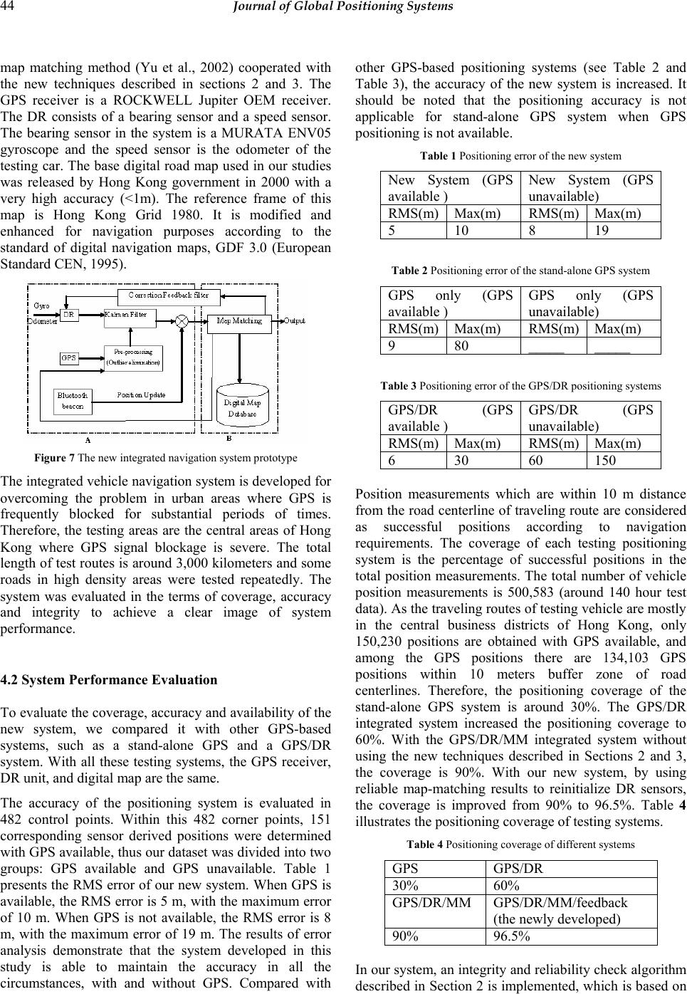 44 Journal of Global Positioning Systems map matching method (Yu et al., 2002) cooperated with the new techniques described in sections 2 and 3. The GPS receiver is a ROCKWELL Jupiter OEM receiver. The DR consists of a bearing sensor and a speed sensor. The bearing sensor in the system is a MURATA ENV05 gyroscope and the speed sensor is the odometer of the testing car. The base digital road map used in our studies was released by Hong Kong government in 2000 with a very high accuracy (<1m). The reference frame of this map is Hong Kong Grid 1980. It is modified and enhanced for navigation purposes according to the standard of digital navigation maps, GDF 3.0 (European Standard CEN, 1995). Figure 7 The new integrated navigation system prototype The integrated vehicle navigation system is developed for overcoming the problem in urban areas where GPS is frequently blocked for substantial periods of times. Therefore, the testing areas are the central areas of Hong Kong where GPS signal blockage is severe. The total length of test routes is around 3,000 kilometers and some roads in high density areas were tested repeatedly. The system was evaluated in the terms of coverage, accuracy and integrity to achieve a clear image of system performance. 4.2 System Performance Evaluation To evaluate the coverage, accuracy and availability of the new system, we compared it with other GPS-based systems, such as a stand-alone GPS and a GPS/DR system. With all these testing systems, the GPS receiver, DR unit, and digital map are the same. The accuracy of the positioning system is evaluated in 482 control points. Within this 482 corner points, 151 corresponding sensor derived positions were determined with GPS available, thus our dataset was divided into two groups: GPS available and GPS unavailable. Table 1 presents the RMS error of our new system. When GPS is available, the RMS error is 5 m, with the maximum error of 10 m. When GPS is not available, the RMS error is 8 m, with the maximum error of 19 m. The results of error analysis demonstrate that the system developed in this study is able to maintain the accuracy in all the circumstances, with and without GPS. Compared with other GPS-based positioning systems (see Table 2 and Table 3), the accuracy of the new system is increased. It should be noted that the positioning accuracy is not applicable for stand-alone GPS system when GPS positioning is not available. Table 1 Positioning error of the new system New System (GPS available ) New System (GPS unavailable) RMS(m) Max(m) RMS(m) Max(m) 5 10 8 19 Table 2 Positioning error of the stand-alone GPS system GPS only (GPS available ) GPS only (GPS unavailable) RMS(m) Max(m) RMS(m) Max(m) 9 80 _____ _____ Table 3 Positioning error of the GPS/DR positioning systems GPS/DR (GPS available ) GPS/DR (GPS unavailable) RMS(m) Max(m) RMS(m) Max(m) 6 30 60 150 Position measurements which are within 10 m distance from the road centerline of traveling route are considered as successful positions according to navigation requirements. The coverage of each testing positioning system is the percentage of successful positions in the total position measurements. The total number of vehicle position measurements is 500,583 (around 140 hour test data). As the traveling routes of testing vehicle are mostly in the central business districts of Hong Kong, only 150,230 positions are obtained with GPS available, and among the GPS positions there are 134,103 GPS positions within 10 meters buffer zone of road centerlines. Therefore, the positioning coverage of the stand-alone GPS system is around 30%. The GPS/DR integrated system increased the positioning coverage to 60%. With the GPS/DR/MM integrated system without using the new techniques described in Sections 2 and 3, the coverage is 90%. With our new system, by using reliable map-matching results to reinitialize DR sensors, the coverage is improved from 90% to 96.5%. Table 4 illustrates the positioning coverage of testing systems. Table 4 Positioning coverage of different systems GPS GPS/DR 30% 60% GPS/DR/MM GPS/DR/MM/feedback (the newly developed) 90% 96.5% In our system, an integrity and reliability check algorithm described in Section 2 is implemented, which is based on 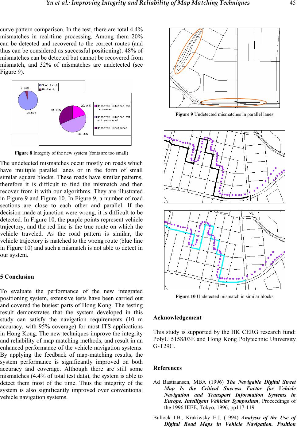 Yu et al.: Improving Integrity and Reliability of Map Matching Techniques 45 curve pattern comparison. In the test, there are total 4.4% mismatches in real-time processing. Among them 20% can be detected and recovered to the correct routes (and thus can be considered as successful positioning). 48% of mismatches can be detected but cannot be recovered from mismatch, and 32% of mismatches are undetected (see Figure 9). Figure 8 Integrity of the new system (fonts are too small) The undetected mismatches occur mostly on roads which have multiple parallel lanes or in the form of small similar square blocks. These roads have similar patterns, therefore it is difficult to find the mismatch and then recover from it with our algorithms. They are illustrated in Figure 9 and Figure 10. In Figure 9, a number of road sections are close to each other and parallel. If the decision made at junction were wrong, it is difficult to be detected. In Figure 10, the purple points represent vehicle trajectory, and the red line is the true route on which the vehicle traveled. As the road pattern is similar, the vehicle trajectory is matched to the wrong route (blue line in Figure 10) and such a mismatch is not able to detect in our system. 5 Conclusion To evaluate the performance of the new integrated positioning system, extensive tests have been carried out and covered the busiest parts of Hong Kong. The testing result demonstrates that the system developed in this study can satisfy the navigation requirements (10 m accuracy, with 95% coverage) for most ITS applications in Hong Kong. The new techniques improve the integrity and reliability of map matching methods, and result in an enhanced performance of the vehicle navigation systems. By applying the feedback of map-matching results, the system performance is significantly improved on both accuracy and coverage. Although there are still some mismatches (4.4% of total test data), the system is able to detect them most of the time. Thus the integrity of the system is also significantly improved over conventional vehicle navigation systems. Figure 9 Undetected mismatches in parallel lanes Figure 10 Undetected mismatch in similar blocks Acknowledgement This study is supported by the HK CERG research fund: PolyU 5158/03E and Hong Kong Polytechnic University G-T29C. References Ad Bastiaansen, MBA (1996) The Navigable Digital Street Map Is the Critical Success Factor for Vehicle Navigation and Transport Information Systems in Europe. Intelligent Vehicles Symposium, Proceedings of the 1996 IEEE, Tokyo, 1996, pp117-119 Bullock J.B., Krakiwsky E.J. (1994) Analysis of the Use of Digital Road Maps in Vehicle Navigation. Position 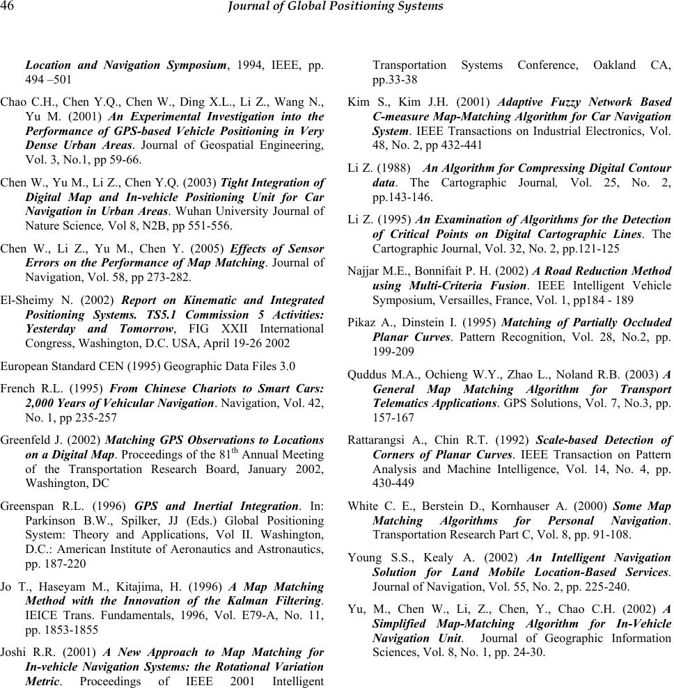 46 Journal of Global Positioning Systems Location and Navigation Symposium, 1994, IEEE, pp. 494 –501 Chao C.H., Chen Y.Q., Chen W., Ding X.L., Li Z., Wang N., Yu M. (2001) An Experimental Investigation into the Performance of GPS-based Vehicle Positioning in Very Dense Urban Areas. Journal of Geospatial Engineering, Vol. 3, No.1, pp 59-66. Chen W., Yu M., Li Z., Chen Y.Q. (2003) Tight Integration of Digital Map and In-vehicle Positioning Unit for Car Navigation in Urban Areas. Wuhan University Journal of Nature Science, Vol 8, N2B, pp 551-556. Chen W., Li Z., Yu M., Chen Y. (2005) Effects of Sensor Errors on the Performance of Map Matching. Journal of Navigation, Vol. 58, pp 273-282. El-Sheimy N. (2002) Report on Kinematic and Integrated Positioning Systems. TS5.1 Commission 5 Activities: Yesterday and Tomorrow, FIG XXII International Congress, Washington, D.C. USA, April 19-26 2002 European Standard CEN (1995) Geographic Data Files 3.0 French R.L. (1995) From Chinese Chariots to Smart Cars: 2,000 Years of Vehicular Navigation. Navigation, Vol. 42, No. 1, pp 235-257 Greenfeld J. (2002) Matching GPS Observations to Locations on a Digital Map. Proceedings of the 81th Annual Meeting of the Transportation Research Board, January 2002, Washington, DC Greenspan R.L. (1996) GPS and Inertial Integration. In: Parkinson B.W., Spilker, JJ (Eds.) Global Positioning System: Theory and Applications, Vol II. Washington, D.C.: American Institute of Aeronautics and Astronautics, pp. 187-220 Jo T., Haseyam M., Kitajima, H. (1996) A Map Matching Method with the Innovation of the Kalman Filtering. IEICE Trans. Fundamentals, 1996, Vol. E79-A, No. 11, pp. 1853-1855 Joshi R.R. (2001) A New Approach to Map Matching for In-vehicle Navigation Systems: the Rotational Variation Metric. Proceedings of IEEE 2001 Intelligent Transportation Systems Conference, Oakland CA, pp.33-38 Kim S., Kim J.H. (2001) Adaptive Fuzzy Network Based C-measure Map-Matching Algorithm for Car Navigation System. IEEE Transactions on Industrial Electronics, Vol. 48, No. 2, pp 432-441 Li Z. (1988) An Algorithm for Compressing Digital Contour data. The Cartographic Journal, Vol. 25, No. 2, pp.143-146. Li Z. (1995) An Examination of Algorithms for the Detection of Critical Points on Digital Cartographic Lines. The Cartographic Journal, Vol. 32, No. 2, pp.121-125 Najjar M.E., Bonnifait P. H. (2002) A Road Reduction Method using Multi-Criteria Fusion. IEEE Intelligent Vehicle Symposium, Versailles, France, Vol. 1, pp184 - 189 Pikaz A., Dinstein I. (1995) Matching of Partially Occluded Planar Curves. Pattern Recognition, Vol. 28, No.2, pp. 199-209 Quddus M.A., Ochieng W.Y., Zhao L., Noland R.B. (2003) A General Map Matching Algorithm for Transport Telematics Applications. GPS Solutions, Vol. 7, No.3, pp. 157-167 Rattarangsi A., Chin R.T. (1992) Scale-based Detection of Corners of Planar Curves. IEEE Transaction on Pattern Analysis and Machine Intelligence, Vol. 14, No. 4, pp. 430-449 White C. E., Berstein D., Kornhauser A. (2000) Some Map Matching Algorithms for Personal Navigation. Transportation Research Part C, Vol. 8, pp. 91-108. Young S.S., Kealy A. (2002) An Intelligent Navigation Solution for Land Mobile Location-Based Services. Journal of Navigation, Vol. 55, No. 2, pp. 225-240. Yu, M., Chen W., Li, Z., Chen, Y., Chao C.H. (2002) A Simplified Map-Matching Algorithm for In-Vehicle Navigation Unit. Journal of Geographic Information Sciences, Vol. 8, No. 1, pp. 24-30. |