Paper Menu >>
Journal Menu >>
 Journal of Global Positioning Systems (2005) Vol. 4, No. 1-2: 258-267 Null-steering LMS Dual-Polarised Adaptive Antenna Arrays for GPS W C Cheuk, M Trinkle & D A Gray CRC for Sensor Signal and Inf ormation Processing, Dept of Electrical and Electronic Engineering, University of Adelaide, Adelaide SA e-mail: dgray@eleceng.adelaide.edu.au Tel: + 61 83036425; Fax: +61 83934369 Received: 27 November 2004 / Accepted: 12 July 2005 Abstract. The implementation of a null-steering antenna array using dual polarised patch antennas is considered. Several optimality criterion for adjusting the array weights are discussed. The most effective criteria minimises the output power of the array subject to maintaining a right hand circular polarisation (RHCP) response on the reference antenna. An unconstrained form of this criteria is derived, in which the reference channel is the RHCP output of the reference antenna and the LHCP output of the reference antenna is included as one of the auxiliary channels. An FPGA implementation of the LMS algorithm is then described. To prevent weight vector drift a variant of the circular leakage LMS algorithm was used. The implementation details of a simplified circular leakage algorithm more suited to an FPGA implementation are presented. This simplified leakage algorithm was shown to have a similar steady state weight vector as the full algorithm. Key words: GPS, Polarisation, Interference Mitigation, Adaptive filters. 1 Introduction A GPS receiver is relatively susceptible to interference and a number of antenna and signal processing techniques have been investigated to overcome this deficiency. These include : • Fixed antenna enhancements: Manz (2000), Kunysz (2000). • Single Channel Adaptive Filters: Dimos et al (1995), Trinkle and Gray (2001). • Adaptive Beamformers: Trinkle and Gray (2001), Zoltowski and Gecan (1995), Jian et al (1998), Fante and Vaccaro (2000). • Polarisation Cancellers: Brassch et al (1998), Trinkle and Cheuk (2003). • Adaptive Beamformers with Polarisation Diversity: Nagai et al (2002), Fante and Vaccaro (2002), Compton (1981). • Modifying the tracking loop of the GPS receivers: Manz et al(2000),Legrand et al (2000). • Integrating GPS and INS sensors: Soloviev and van Grass (2004). In this paper combined spatial and polarisation null steering are considered. A single GPS antenna with an adaptive polarisation response can be used to reject interferences with polarisations other than the GPS signal. The GPS signal uses RHCP (right hand circular polarisation), i.e., it contains both horizontal and vertical polarizations 90 degrees out of phase; thus it is possible to remove any linearly polarised signal with only a 3 dB loss in GPS signal power see e.g. Brassch et al (1998). The key idea of polarisation cancellers is thus to reject th e interference by adaptively mismatching the polarisation response of the antenna to the polarisation of the interfering signal. Adaptive polarisation antennas can be implemented by adaptively combining the two outputs of a dual polarised patch antenna see e.g. Brassch et al (1998), Compton (1981). Clearly this technique becomes ineffective if the interference has the same polarisation as the GPS signal (i.e., RHCP ) . Single antenna polarisation cancellers operate purely in the polarisation domain, while adaptive beamformers operate only in the spatial (angle domain). It is possible to combine these two domains in a single algorithm by applying beamforming techniques to an antenna array with dual polarised antenna elements. Using a such an array, will approximately double the degrees of freedom available for interference cancellation compared with using a conventional antenna array see e.g. Jain (1998), Trinkle and Cheuk (2003), Nagai et al (2002), and it has  Cheuk: Null-steering LMS Dual-Polarised Adaptive Antenna Arrays for GPS 259 recently been shown in Jian et al (1998) and Fante and Vaccaro (2002) that GPS polarimetric antenna arrays can cancel more interferences than a standard antenna array with the same number of antenna elements. Thus polarisation diversity can be used to significantly reduce the size of GPS antenna arrays, which is important in many applications. Field Programmable Gate Array, FPGA, technology has lately become an attractive alternative for the implementation of a wide range of DSP applications because of its flexibility and speed. An FPGA allows a large number of multipliers and accumulators to be configured and inter-connected in such a way as to suit a particular algorithm. This fine-grain parallelism allows most adaptive beamforming techniques to be implemented much more efficiently than on a standard DSP. Algorithms implemented on the largest of the current generation FPGAs can achieve several hundred Giga Operati o ns per Seconds (GOPs) The FPGA implementation of an adaptively null-steering dual-polarised antenna array is proposed. The novelty of this approach lies in • The choice of the reference and auxiliary channels in the power minimisation algorithm. • The use of a modified version of the complex LMS algorithm to minimise computations. • The use of Hilbert transforms to generate the analytic signal. • The use of the circular leakage LMS algorithms rather than the standard leaky LMS to prevent weight vector drift. • A simplification of the circular leakage LMS algorithm more suited to FPGA implementation. 2 Digital Null-Steering Structure System Architecture A polarimetric adaptive antenna array is placed in front of the GPS receiver. Each element of the array is a patch antenna with two outputs corresponding to the horizontal and vertical polarizations of the received signal. See Figure 1 for a four channel digital null-steering system using two dual-polarized antenna elements. Figure 1. Basic structure of digital null-steerer using a polarimetric antenna array y : Beamformer output w : Beamformer weight vector e : Estimation error u : Antenna output. HT : Hilbert Transform  260 Journal of Global Positioning Systems In this example the horizontal component of the first antenna is used as a reference channel as originally proposed in Fante and Vaccaro (2002). The subscript H denotes the horizontal polarization, V denotes the vertical polarization, I denotes the real part of the complex signal, and Q denotes the imaginary part of the complex signal. The output of each polarization channel is converted into a digital signal using an analog to digital (A/D) converter. Since the L1 band GPS signal is transmitted at 1.575GHz and most A/D converters do not have an input bandwidth large enough to sample the GPS signal, a down-converter is used to convert the incoming GPS signal to a lower intermediate frequency. The digital signal from the A/D converter is then fed into an FPGA, see Figure 1, which implements further filtering and the complete adaptive antenna array processing. The single channel output, y, of the adaptive antenna array is then converted back to the analogue domain by a D/A converter and after further analogue filtering and mixing the signal can be played into a standard GPS receiver. Adaptive Al g orithm Optimum null-steering algorithms are usually applied to antenna arrays by simply minimising the output power of a weighted sum of receiver outputs subject to one of the multiplier weights (the reference channel) being fixed at unity, see e.g. Trinkle and Gray (2001). This leads to an optimum weight vector given by cRc cR wH1 1 − − = where T c]0,,0,0,1[ …= and R is the covariance matrix of the receiver outputs defined by { } )()( kukuER H =. The vector )(ku contains the antenna outputs at time s kt where s t is the sampling interval. With reference to Figure 1, it is assumed that each channel is Hilbert transformed allowing the use of the analytic (complex) signal representation. For polarimetric antenna arrays, better performance may be achieved by choosing as the reference channel the right hand circularly polarized component of the reference antenna, thus avoiding a 3dB loss in SNR of desired GPS signals in the absence of interferences see e.g. Trinkle and Cheuk (2003). To handle the dual channels of each polarised antenna the vector of complex receiver outputs is written as: ( ) T NVNHVHVH kukukukukukuku ][],[],...[],[],[],[)( 2211 = (2.1) where ][][][kjukuku nHQnHInH + = and ][][][ kjukuku nVQnVInV + = . For right hand circular polarisation the horizontal and vertical components of the electric field are –90 degrees out of phase with each other. Thus, for an ideal narrowband RHCP signal the complex vector of outputs from the first reference channel, is given by ⎥ ⎦ ⎤ ⎢ ⎣ ⎡ − = ⎥ ⎦ ⎤ ⎢ ⎣ ⎡ =j kts ku ku ku s V H1 ][ ][ ][ )( 1 1 1 Combining, with complex weights, H w1 and V w1, the outputs of the horizontal and vertical channels, such that the response due to a circularly polarised signal of unit amplitude is fixed at unity implies that the complex weights are constrained to satisfy 1 1 * 1 *=− VH jww . Generalising for the full array, the constraint becomes 1=cwH where T jc ]0,,0,,1[ …−= . From Trinkle and Cheuk (2003), the optimum weight vector becomes cRc cR wH1 1 − − =. (2.2) The advantage of this cons traint, is that it allows, for an N channel receiver, N-1 nulls to be formed as opposed to the previous approaches which restricted the number of nulls to be N-2 see e.g. Trinkle and Cheuk (2003). In order impose this constraint with an unconstrained LMS adaptive algorithm, an orthogonal projection matrix is used. This transformation takes the horizontally and the vertically polarized complex signals from the dual polarized antenna and converts them to a RHCP signal and another signal that is orthogonal to the RHCP signal (LHCP) as illu strated in Figure 2 below.  Cheuk: Null-steering LMS Dual-Polarised Adaptive Antenna Arrays for GPS 261 Figure 2. Orthogonal pr ojec tion matrix. The orthogonal projection matrix transformation is given by ⎥ ⎦ ⎤ ⎢ ⎣ ⎡ ⎥ ⎦ ⎤ ⎢ ⎣ ⎡− = ⎥ ⎦ ⎤ ⎢ ⎣ ⎡ ][ ][ 1 1 ][ ][ 1 1 1 1 ku ku j j ku ku H V L R The outputs of the orthogonal projection matrix are then fed to the adaptive algorithm. The RHCP channel, ][ 1ku R, is the reference channel, as it has the same polarization as the GPS signal. The orthogonal projection of the RHCP channel, i.e., ][ 1ku L is the first auxiliary channel, which is multiplied by a weight determined by the adaptive algorithm. The other auxiliary channels are the vertical and horizontally polarised outputs of the second anten na. Note that there is no need to transform these outputs into right and left circularly polarised components as the signals are assumed narrow-band so the required phase shift can be incorporated into the adaptive alg orithm. To estimate the weights we could first estimate R from the input data and then substitute into Eq. 2.2 to give the desired weights. This approach was not taken as it would require a matrix inversion which is not simple to implement in an FPGA. To avoid direct matrix inversion, gradient descent algorithms are used to iteratively minimise the mean square error. As the output of the beamformer needs to be converted back to a real signal, a simplified version, of the standard complex LMS algorithm was applied. The trade-off between this algorithm and the full complex LMS algorithm has been considered in Horowitz and Senne (1981). 3 Implementation of the LMS Algorithm The use of finite precision arithmetic in the LMS algorithm can cause drift in the weight vectors, Sethares et al (1986), particularly in the presence of strong interferences. To overcome this a leakage factor can be incorporated into the LMS algorithm. An investigation of a number of leaky LMS algorithms is carried out below. Leaky LMS Algorithm The leaky LMS algorithm prevents weight vector drift in finite precision implementations by inserting a leakage factor, L α , into the weight vector update loop. This leakage factor avoids weight vector drift by containing the energy in the impulse response of the LMS adaptive filter see e.g. Haykin (2002). The leaky LMS algorithm is given by : { } ][)()()1()1( kekukwkw L µ µα + − = + (3.1) where ][ke , the error signal, is given by )()()()()(][][ 1kukwkukukwkdke H R H ′ −= ′ −= and () T NVNHVHLkukukukukuku ][],[....],........[],[],[)( 221 = ′ The difference between the leaky LMS and the conventional LMS algorithm is the leakage factor )1( L µα − , the first term on the right hand side of the Eq. 3.1. To stabilize the algorithm (i.e., to avoid overflows), the leakage factor, L α , must satisfy the condition µ α 1 0<≤L (3.2) The leakage factor can also prevent stalling in the LMS algorithm. Stalling occurs when the correction term (i.e. )]()([ keku µ ) in the weight update equation is smaller than the least significant bit (LSB), thus the LMS algorithm will stop adapting. Stalling can also be prevented by dithering the error term. R u1 L u1 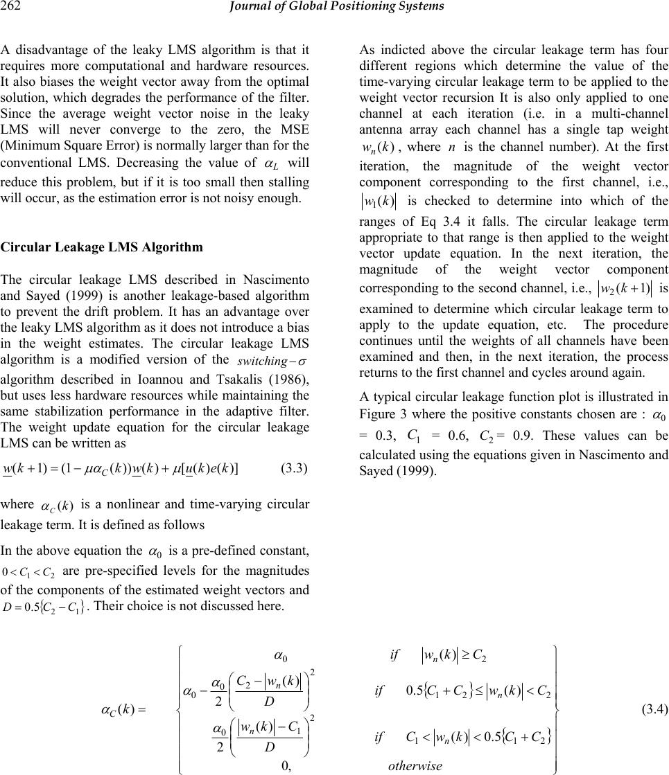 262 Journal of Global Positioning Systems A disadvantage of the leaky LMS algorithm is that it requires more computational and hardware resources. It also biases the weight vector away from the optimal solution, which degrades the performance of the filter. Since the average weight vector noise in the leaky LMS will never converge to the zero, the MSE (Minimum Square Error) is normally larger than for the conventional LMS. Decreasing the value of L α will reduce this problem, but if it is too small then stalling will occur, as the estimation error is not noisy enough. Circular Leakage LMS Algorithm The circular leakage LMS described in Nascimento and Sayed (1999) is another leakage-based algorithm to prevent the drift problem. It has an advantage over the leaky LMS algorithm as it does not introduce a bias in the weight estimates. The circular leakage LMS algorithm is a modified version of the σ − switching algorithm described in Ioannou and Tsakalis (1986), but uses less hardware resources while maintaining the same stabilization performance in the adaptive filter. The weight update equation for the circular leakage LMS can be written as )]()([)())(1()1( kekukwkkw C µ µα +−=+ (3.3) where )(k C α is a nonlinear and time-varying circular leakage term. It is defined as follows In the above equation the 0 α is a pre-defined constant, 21 0CC << are pre-specified levels for the magnitudes of the components of the estimated weight vectors and {} 12 5.0 CCD −=. Their choice is not discussed here. As indicted above the circular leakage term has four different regions which determine the value of the time-varying circular leakage term to be applied to the weight vector recursion It is also only applied to one channel at each iteration (i.e. in a multi-channel antenna array each channel has a single tap weight )(kwn, where n is the channel number). At the first iteration, the magnitude of the weight vector component corresponding to the first channel, i.e., )( 1kw is checked to determine into which of the ranges of Eq 3.4 it falls. The circular leakage term appropriate to that range is then applied to the weight vector update equation. In the next iteration, the magnitude of the weight vector component corresponding to the second channel, i.e., )1( 2+kw is examined to determine which circular leakage term to apply to the update equation, etc. The procedure continues until the weights of all channels have been examined and then, in the next iteration, the process returns to the first channel and cycles around again. A typical circular leakage function plot is illustrated in Figure 3 where the positive constants chosen are : 0 α = 0.3, 1 C = 0.6, 2 C= 0.9. These values can be calculated using the equations given in Nascimento and Sayed (1999). {} {} ⎪ ⎪ ⎪ ⎪ ⎭ ⎪ ⎪ ⎪ ⎪ ⎬ ⎫ ⎪ ⎪ ⎪ ⎪ ⎩ ⎪ ⎪ ⎪ ⎪ ⎨ ⎧ +<< ⎟ ⎟ ⎠ ⎞ ⎜ ⎜ ⎝ ⎛− <≤+ ⎟ ⎟ ⎠ ⎞ ⎜ ⎜ ⎝ ⎛− − ≥ = otherwise CCkwCif D Ckw CkwCCif D kwC Ckwif k n n n n n C ,0 5.0)( )( 2 )(5.0 )( 2 )( )( 211 2 1 0 221 2 2 0 0 20 α α α α α (3.4)  Cheuk: Null-steering LMS Dual-Polarised Adaptive Antenna Arrays for GPS 263 Figure 3. Circular leakage fu n ct i o n . When implementing the circular leakage in real time on the FPGA, one of the main factors that needs to be consider is latency. The standard LMS weight update loop has a delay of one clock cycle. From Eq. 3.3 and Eq. 3.4 the circular leakage algorithm requires six multiplications, two subtractions and two divisions per weight vector update. This introduces significant latency in the weight estimation loop, requiring it to take more than one clock cycle to complete all the calculations. Such a delay would cause the LMS algorithm to behave like the DLMS (Delayed Least Mean Square algorithm), resulting in increased convergence times and an overall loss in performance. Modified Circular Leakage LMS Algori thm As the adaptive null-steerer is to operate in real time, the above circular leakage algorithm was replaced by a simplified linear algorithm that required less arithmetic operations. The linear equations for determining the leakage factor C α are given by Eq. 3.5 has the same four regions as Eq. 3.3, but since the quadratic terms are replaced by linear ones the modified function uses less multiplications and no division and so its computational complexity is significantly reduced. As a result, the modified function can complete the weight update calculation in one clock cycle, making it more suitable for a real time implementation. Figure 4 shows a plot of c α for the standard circular- leakage (blue), and the modified circular-leakage (red). As shown in the plot, the original function rises quickly when the weight estimation reaches the 1 C (0.88) bound, it then goes up almost linearly as w increases, and then rolls off smoothly shortly before reaching the 2 C(0.93) bound. {} {} ⎪ ⎪ ⎭ ⎪ ⎪ ⎬ ⎫ ⎪ ⎪ ⎩ ⎪ ⎪ ⎨ ⎧ +<<− <≤++− ≥ = otherwise CCkwCifCw CkwCCifw Ckwif n n n C ,0 5.0)()(4.17 )(5.058.0)9133.0(2.5 )( 2111 221 20 α α (3.5) )(kwn  264 Journal of Global Positioning Systems Figure 4. Simplified/s t andard circular leakage function with 93.0,88.0 21 = = CC . The linear approximation has a slightly higher numerical value of leakage factor (c α ) at the same weight value (w) compared with the standard one. This ensures stability of the algorithm. Figure 5 shows simulation results indicating that the modified circular leakage algorithm remains stable and behaves almost the same as the original one albeit at what appears to be a higher level of misadjustment noise. 4 FPGA Implementation This section considers the FPGA implementation of the adaptive null-steerer. The FPGA has four main processing modules including, digital decimation filtering, Hilbert transform filtering and the implementation of the LMS adaptive algorithm using the simplified circular leakage algorithm. The signal flow diagram is illustrated in Figure 6. Figure 5 w for standard/simplified circular leakage 1667.0= o µα , 93.0,88.0 21 = = CC . 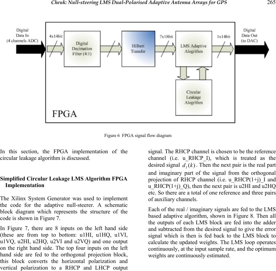 Cheuk: Null-steering LMS Dual-Polarised Adaptive Antenna Arrays for GPS 265 Figure 6 FPGA signal flow diagram In this section, the FPGA implementation of the circular leakage algorithm is discussed. Simplified Circular Leakage LMS Algorithm FPGA Implementation The Xilinx System Generator was used to implement the code for the adaptive null-steerer. A schematic block diagram which represents the structure of the code is shown in Figure 7. In Figure 7, there are 8 inputs on the left hand side (these are from top to bottom: u1HI, u1HQ, u1VI, u1VQ, u2HI, u2HQ, u2VI and u2VQ) and one output on the right hand side. The top four inputs on the left hand side are fed to the orthogonal projection block, this block converts the horizontal polarization and vertical polarization to a RHCP and LHCP output signal. The RHCP channel is chosen to be the reference channel (i.e. u_RHCP_I), which is treated as the desired signal )(kdI. Then the next pair is the real part and imaginary part of the signal from the orthogonal projection of RHCP channel (i.e. u_RHCP(1+j)_I and u_RHCP(1+j)_Q), then the next pair is u2HI and u2HQ etc. So there are a total of one reference and three pairs of auxiliary channels. Each of the real / imaginary signals are fed to the LMS based adaptive algorithm, shown in Figure 8. Then all the outputs of each LMS block are fed into the adder and subtracted from the desired signal to give the error signal which is then is fed back to the LMS block to calculate the updated weights. The LMS loop operates continuously, at the input sample rate, and the optimum weights are continuously estimated.  266 Journal of Global Positioning Systems Figure 7 Four channel dig i t al n u l l -steerer - FPGA schematic. Figure 8 LMS base algorithm block - FP GA sch ematic.  Cheuk: Null-steering LMS Dual-Polarised Adaptive Antenna Arrays for GPS 267 The circular leakage algorithm is implemented in VHDL, as shown in Figure 7 in the block called circular leakage. It has six inputs on the right hand side and same number of outputs in left hand side. It implements the if/then statement of Eq. 3.5. In each iteration, it measures the weight estimate for one channel, and outputs the leakage value according to the Eq. 3.5. This value is then fed back to the leak_out (Figure 8), and subtracted from the current weight vector component. Then in the next iteration, the circular leakage block will check the wof the next channel. Conclusions The FPGA implementation of an adaptive LMS algorithm suitable for dual polarised GPS antenna arrays has been presented. The LMS algorithm minimises the output power of the array while maintaining unity gain for RHCP signals on the reference antenna. To prevent weight vector drift in the LMS algorithm a circular leakage algorithm was implemented. A simplified version of the leakage algorithm was derived which introduces minimal additional bias and allows the LMS updates to occur at the input data rate. The complete algorithm was implemented on an FPGA using the Xilinx System Generator. References Manz A.; Shallerg K.; Shloss P.; (2000): Improving WAAS Receiver Radio Frequency Interference Rejection. ION GPS 200, September 2000, pp471-479 Kunysz W. (2000): A Novel GPS Survey Antenna. ION NTM 2000, January 2000 Kunysz W. (2000): High Performance GPS Pinwheel Antenna. ION NTM 2000, September 2000 Dimos G.; Upadhyay T.; Jenkins T. (1995): Low-Cost Solution to Narrowband GPS Interference Problem Proc IEEE 1995 Naecon Meeting, vol I pp145-153 May 1995. Trinkle M.; Gray D. (2001): GPS Interference Mitigation; Overview and Experimental Results. SatNav 2001, July, 2001. Braasch M. S.; Rosen M. W. (1998): Low-Cost GPS Interference Mitigation Using Single Aperture Cancellation Techniques. Navigation 2000, 1998 ION National Technical Meeting. Zoltowski M. D.; Gecan A. S. (1995): Advanced Adaptive Null Steering Concepts for GPS. MILCOM 95 Vol. 3, pp. 1214-1218. Jian K.; Guosheng R.; Xizhang K. (1998): Power Inversion Adaptive Algorithm for GPS Receiver Antijamming. International Radar Symposium, September 1998. pp.1395-1401. Fante R. L.; Vaccaro J. J. (2000): Wideband Cancellation of Interference in a GPS Receive Array. IEEE Transaction on Aerospace and Electronic Systems Vol. 36, No. 2 April 2000. Trinkle M.; Cheuk W. (2003): Null-Steering GPS Dual- Polarized Antenna Arrays. SatNav July 2003. Nagai E. C.; Blejer D. J.; Phuong T.; Herd J. (2002): Anti- jam Performance of Small GPS Polarimetric Array. IEEE Antennas and Propagation Society Int. Symp. 2002 Digest, Vol. 2, 16-21 June 2002, pp. 128-131. Fante R. L.; Vaccaro J. J. (2002): Evaluation of Adaptive Space-Time-Polarization Cancellation of Broadband Interference. Proceedings of the 2002 IEEE Precision Location & Navigation Symposium pp.1-3. Compton R. T. JR. (1981): On the Performance of a Polarization Sensitive Adaptive Array. IEEE Transaction on Antennas and Propagation, Vol. AP-29, No. 5, pp. 718-725, September 1981. Legrand F.; Macaiau C.; Issler J. L.; Lestarquit L.; Mehlen C. (2000): Improvement of Pseudo Range Measurements Accuracy By Using Fast Adaptive Bandwidth Lock Loops. ION GPS 200, September 2000, pp. 2346-2356 Soloviev A.; van Grass F. (2004): Combining Low-Cost Inertial System with GPS Applications for General Aviation. GPS World, March 2004 pp. 38-45. Horowitz L.; Senne D. (1981): Performance Advantage of Complex LMS for Controlling Narrow-Band Adaptive Arrays. IEEE Transactions on acoustics, and signal processing, Vol. ASSP-29, NO.3 June 1981. Sethares W. A.; Dale A.; Lawrence C.; Johnson R. JR.; Bitmead R. R. (1986): Parameter Drift in LMS Adaptive Filters. IEEE Transactions on Acoustic, Speech and Signal Processing Vol. ASSP-34, No 4, August 1986. Nascimento V. H.; Sayed A. H. (1999): Unbiased and Stable Leakage-Based Adaptive Filter. IEEE Transactions on Signal Processing, Vol. 47, No. 12 December 1999. Ioannou P.; Tsakalis K. Robust discrete-time adaptive control in Narendra K. S, Ed.,(1986): Adaptive and Learning Systems: Theory and Applications. New York: Plenum, 1986, pp. 73-87. Haykin S. (2002): Adaptive Filter Theory 4th Edition. Prentice Hall 2002. |