Wireless Sensor Network
Vol.5 No.5(2013), Article ID:31780,5 pages DOI:10.4236/wsn.2013.55014
A Chain-Based Routing Protocol to Maximize the Lifetime of Wireless Sensor Networks
1LIFC UFR ST, Besançon Cedex, France
2Tlemcen STIC Laboratory, Abou-Bakr Belkaïd University, Tlemcen, Algeria
Email: mhadjila_2002@yahoo.fr, herve.guyennet@femto-st.fr, m_feham@mail.univ-tlemcen.dz
Copyright © 2013 Mourad Hadjila et al. This is an open access article distributed under the Creative Commons Attribution License, which permits unrestricted use, distribution, and reproduction in any medium, provided the original work is properly cited.
Received April 9, 2013; revised May 8, 2013; accepted May 23, 2013
Keywords: Wireless Sensor Networks; Chain; Energy Conservation; Lifetime
ABSTRACT
Energy conservation is a key issue in the design of systems based on wireless sensor networks. Clustering routing protocols have been developed in order to reduce the network traffic toward the sink and therefore prolong the network lifetime. An alternative of clustering is to build chains instead of clusters. In this context, we propose a routing protocol for Wireless Sensor Networks (WSN). It is based on constructing multiple chains in the direction of the sink. The first node of each chain sends data to the closest node in the same chain. This latter collects, aggregates and transmits data to the next closest node. This process repeats until reaching the last node, which aggregates and transmits data directly to the sink. An improvement of this approach is proposed. It works as follows: In addition to forming multiple chains as previously, it constructs a main chain, which includes leader node of each chain. Since, initially all main chain nodes have the same amount of power, the nearest node to the sink aggregates data from others then transmits it to the sink. In the next transmission, main chain node having the higher residual energy performs this task. Compared with the first approach, simulation results show that improvement approach consumes less energy and effectively extends the network lifetime.
1. Introduction
Today, progress in the field of microelectronics and wireless communication technologies is used to create small systems communicating with sensors at a reasonable cost [1]. These communicating micro-components are called sensors. These technological advances make possible the deployment of wireless sensor networks. A Wireless Sensor Network [2] is a set of communicating nodes, each consisting of four entities: a radio module for exchanging messages via the wireless medium, one or more sensors/actuators with a specific task, such as motion detection or the activation of a contact, a microcontroller responsible for needed processing, and an energy source which supplies the whole. The wireless sensor networks are increasingly deployed randomly or in deterministic way in various areas covering military applications such as target tracking, monitoring of wild animals in the forest, habitat monitoring, industrial applications, earth movement detection, healthcare applications, surveillance and so on [2]. This technology must offer autonomous solutions, that is to say, capable of saving energy and self-configuring. This makes it more attractive because these concepts do not apply to wired networks or even most solutions.
Figure 1 shows a typical architecture of a network of wireless sensors [3]. The data collected by sensors are fed directly or via other sensors to a collection point called base station or sink. This network communicates to a network of another type that leads to unit control system. The intermediate network used to deport the checkpoint from the place of deployment of the sensor

Figure 1. Sensor network architecture [5].
network may very well be the GSM network, a wireless network such as a wired network (internet).
However, to make wireless sensor networks feasible to be employed, a number of requirements in the design and operation of the network need to be satisfied. Since sensor nodes are powered by limited energy [4], energy conservation is commonly considered as a very critical resource that must be used very sparingly. In addition, it could be impossible or inconvenient to replace or recharge the battery, because nodes may be deployed in a hostile or unpractical environment.
To extend the lifespan of a WSN, we proposed in the present paper an algorithm that forms a multiple chain in the direction of the sink. Data transmission is performed from node to node and the last node sends directly to the sink. An improved version of this latter consists at constructing a main chain between the last nodes of each chain. The remainder of this paper is structured as fol lows. Related work is discussed in Section 2. In Section 3, we introduce the proposed approach. Section 4 shows the simulation results of our method. And finally, conclusions are given in Section 5.
2. Related Work
In recent years, clustering routing protocols have been developed in order to reduce the network traffic toward the sink [6-12]. Moreover, cluster heads have been used to enhance the efficiency of the energy-aware routing protocols [13]. An alternative of clustering is to build chains instead of clusters. PEGASIS [14] is the first routing protocol that uses chain. The main idea in PEGASIS is for each node to receive from and transmit to close neighbors and take turns being the leader for transmission to the base station. This approach will distribute the energy load evenly among the sensor nodes in the network. The base station can compute this chain and broadcast it to all the sensor nodes. Authors in [15] proposed two new algorithms under name PEDAP (Power Efficient Data gathering and Aggregation Protocol), which are near optimal minimum spanning tree based routing schemes, where one of them is the power-aware version of the other. Y. Yu and Y. Song [16] proposed an Energy-Efficient Chain-Based routing protocol (EECB) that is an improvement over PEGASIS. EECB uses distances between nodes and the base station and remaining energy levels of nodes to decide which node will be the leader that takes charge of transmitting data to the base station. Also, EECB adopts distance threshold to avoid formation of LL (Long Link) on the chain. In [17], authors proposed a protocol based on the PEGASIS protocol but using an improved ant colony algorithm rather than the greedy algorithm to construct the chain. Compared with the original PEGASIS, this one, PEGant, can achieve a global optimization. It forms a chain that makes the path more even distributed and the total square of transmission distance much less. Young-Long Chen & al [18] proposed Intra-Grid PEGASIS topology architecture, which is an architecture based on PEGASIS topology; in this architecture, the sensor area is divided into several network grids, meanwhile, the nodes of each network grid is deployed in random, then the nodes within the network grid are connected, finally, all the network grids are connected. In [19] a new algorithm named PEGASIS algorithm improving based on Double Cluster Head (PDCH) was proposed to make every notes load balance and extent the network lifetime. Authors chose double cluster heads in one chain and used hierarchical structure in the new algorithm on the basis of avoiding the long chain existing.
3. Description of the Proposed Algorithm
In the following, we present our proposed algorithm. Assume a WSN consisting of n nodes randomly deployed in an area of sides X and Y. The sink is located outside the area of sensor nodes. We partition all nodes into m chains.
3.1. Chains Formation
We divide X into m intervals.
Let  (1)
(1)
We construct the different chains by employing (2).
 (2)
(2)
where I = [1, n] and x(node(i)) denotes abscissa of i-th node.
After chains construction, we proceed to sort them according to their ordinates. The following pseudo-code shows this operation.
For I =1 to m
For j = 1 to Ic(i) − 1
For k = j + 1 to Ic(i)
If y(node(j)) > y(node(k)) then
z = y(node(j));
y(node(j)) = y(node(j + 1));
y(node(j + 1)) = z;
End If End For
End For End For.
Ic(j) denote the set of nodes belonging to the j-th chain.
The first node in each chain sends data to the next node, this latter aggregates data and sends it to the next and so on. When the data reaches the last node, this transmits it in single hop to the sink (see Figure 2). Over time, some nodes in the chain deplete their energies and therefore corresponding chains will need to be updated.
3.2. Updating Chains
Figure below depicts a chain before updating, it means when all nodes have an energy level greater than 0. Node 6 is the nearest node to the sink.
Figure 3 represents a chain formed by six nodes. If for example node 4 depletes its energy, then node 3 bypasses node 4 and sends data directly to node 5 in the next transmission (see Figure 4).
An improved version of this algorithm is proposed. In addition to the multiple chains, it builds a main chain grouping the last nodes of each chain (see Figure 5).
The closest node does initially data transmission from the main chain to the sink since all nodes have the same amount of energy. In the next transmission, the node that has the higher residual energy performs this task. Figure 6 illustrates the data transmission mode from main chain to the sink.
4. Evaluation
Before presenting simulation results, we make the following assumptions:
• Both sensor nodes and base station are stationary after

Figure 2. Formation chains and ending transmission.

Figure 3. Chain before updating.

Figure 4. Chain after updating.

Figure 5. Formation of the main chain.
being deployed in the field.
• Base station is located outside the area of the sensor nodes.
• The wireless sensor network consists of the homogeneous sensor nodes.
• All sensor nodes have the same initial energy.
• Base station is not limited in terms of energy, memory and computational power.
• The radio channel is symmetric such that energy consumption of transmitting data from node X to node Y is the same as that of transmission from node Y to node X.
• Each sensor nodes can operate either in sensing mode to monitor the environment parameters and transmit to the base station or cluster head mode to gather data, compress it and forward to the base station.
For the radio model, we assume a simple model where the transmitter dissipates energy to run radio electronics and the power amplifier, and the receiver dissipates energy to run the radio electronics. The following equations represent the amount of energy consumption in transmitting a packet with k bits over d distance [10]:
 (3)
(3)
 (4)
(4)

Table 1. Simulation parameters.
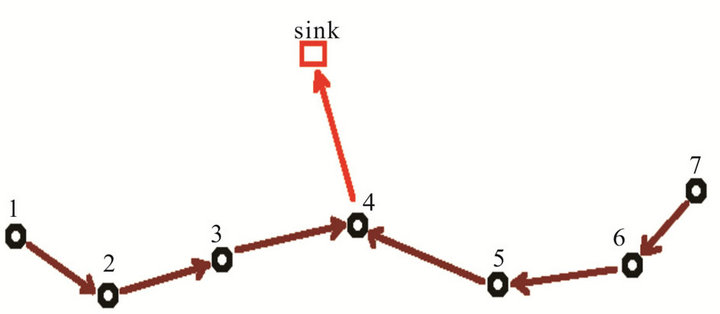
Figure 6. Data transmission mode in the main chain.
where Eelec is the amount of energy consumption per bit to run the transmitter or receiver.
Efs and Emp are respectively energy in free space and multipath model.
ERX is the amount of energy consumption in receiving a packet with k bits.
Matlab software has been used for the simulation work. We have randomly deployed 100 nodes in an area of 100 × 100 m2, the sink is located at (150, 50). Each sensor node transmits a 4000 bits message. The initial energy supplies to each sensor node is 0.1 J. We note that the number of chains is chosen equal to square root of the total number of nodes. The parameter settings used in the simulation are listed in Table 1.
EDA means energy data aggregation.
Two metrics are chosen in order to evaluate the proposed schemes, which are energy consumption and the number of alive nodes. We named the first algorithm “Chain-Based 1” and its improvement “Chain-Based 2”. From the simulation results shown in Figures 7 and 8, it was observed that the improved (Chain-Based 2) scheme consumes less power than the first algorithm. This is due

Figure 7. Energy consumption vs. number of rounds.

Figure 8. Residual energy vs. number of rounds.
to the presence of the main chain, which reduces the long transmission from leaders nodes (last nodes) to the sink.
In Figure 9, we have compared the number of alive nodes in the two approaches. We see clearly that the first node dies after 31 rounds in the first scheme while the first node dies after 176 rounds in the improved scheme. Therefore, improved scheme is more efficient in term of network lifetime than the first scheme.
5. Conclusion
In this paper, we introduce wireless sensor networks routing algorithms using chain principle instead of forming clusters. The first algorithm consists in constructing multiple chains in the direction of the sink, each with a leader node, which is the last, and the nearest node to the sink. An improved scheme of this latter consists at forming a main chain grouping the leader nodes. One node

Figure 9. Number of alive nodes vs. number of rounds.
from this main chain collects, aggregates and transmits data to the remote sink. As the simulation results reveal, the improved algorithm reduces energy consumption and consequently maximizes the lifetime of the WSNs.
REFERENCES
- C. Li, H. Zhang, B. Hao and J. Li, “A Survey on Routing Protocols for Large-Scale Wireless Sensor Networks,” Sensors, Vol. 11, No. 4, 2011, pp. 3498-3526. doi:10.3390/s110403498
- I. F. Akyildiz, W. Su, Y. Sankarasubramaniam and E. Cayirci, “Wireless Sensor Networks: A Survey,” Computer Networks (Elsevier), Vol. 38, No. 4, 2002, pp. 393- 422. doi:10.1016/S1389-1286(01)00302-4
- G. Anastasi, M. Conti, M. Di Francesco and A. Passarella, “Energy Conservation in Wireless Sensor Networks: A Survey,” Elsevier, Ad Hoc Networks, Vol. 7, No. 3, 2009, pp. 537-568. doi:10.1016/j.adhoc.2008.06.003
- J. Hill and D. Culler, “A Wireless Embedded Sensor Architecture for System Level Optimization,” International Research IRB-TR-02-00N, 2002.
- G. Anastasi, M. Conti, M. Di Francesco and A. Passarella, “How to Prolong the Lifetime of Wireless Sensor Networks,” In: M. Denko and L. Yang, Eds., Mobile Ad Hoc and Pervasive Communications, American Scientific Publishers, CRC Press, Boca Raton, 2011. http://info.iet.unipi.it/~anastasi/papers/Yang.pdf
- S. Bandyopadhyay and E. Coyle, “An Energy-Efficient Hierarchical Clustering Algorithm for Wireless Sensor Networks,” 22nd Annual Joint Conference of the IEEE Computer and Communications (INFOCOM 2003), San Francisco, 30 March-3 April 2003, pp. 1713-1723.
- S. Banerjee and S. Khuller, “A Clustering Scheme for Hierarchical Control in Multi-Hop Wireless Networks,” 20th Annual Joint Conference of the IEEE Computer and Communications Societies (INFOCOM 2001), Anchorage, 22-26 April 2001, pp. 1028-1037.
- A. Boukerche, R. W. Pazzi and R. B. Araujo, “Fault-Tolerant Wireless Sensor Network Routing Protocols for the Supervision of Context-Aware Physical Environments,” Journal of Parallel and Distributed Computing, Vol. 66, No. 4, 2006, pp. 586-599. doi:10.1016/j.jpdc.2005.12.007
- A. Boukerche and A. Martirosyan, “An Energy-Aware and Fault Tolerant Inter-Cluster Communication Based Protocol for Wireless Sensor Networks,” Global Telecommunications Conference (GLOBECOM’07), Washington, 26-30 November 2007, pp. 1164-1168.
- W. Heinzelman, A. Chandrakasan and H. Balakrishnan, “Energy-Efficient Communication Protocols for Wireless Sensor Networks,” Proceedings of the 33rd Annual Hawaii International Conference on System Sciences (HICSS), Hawaii, 4-7 January 2000, pp. 3005-3014. doi:10.1109/HICSS.2000.926982
- A. Manjeshwar and D. P. Agrawal, “TEEN: A Routing Protocol for Enhanced Efficiency in Wireless Sensor Networks,” 15th Conference on Parallel and Distributed Processing Symposium, San Francisco, 23-27 April 2000, pp. 2009-2015.
- A. Manjeshwar and D. P. Agrawal, “APTEEN: A Hybrid Protocol for Efficient Routing and Comprehensive Information Retrieval in Wireless Sensor Networks,” 2nd International Workshop on Parallel and Distributed Computing Issues in Wireless Networks and Mobile Computing, Ft. Lauderdale, 15-19 April 2002, pp. 195-202.
- A. M, A. Boukerche and R. W. Nelem Pazzi, “A Taxonomy of Cluster-Based Routing Protocols for Wireless Sensor Networks,” IEEE International Symposium on Parallel Architectures, Algorithms, and Networks, Sydney, 7-9 May 2008, pp. 247-253.
- S. Lindsey and C. S. Raghavendra, “PEGASIS: Power Efficient Gathering in Sensor Information Systems,” Proceedings of the IEEE Aerospace Conference, Vol. 3, Big Sky, 2002, pp. 1125-1130.
- H. O. Tan and I. Korpeoglu, “Power Efficient Data Gathering and Aggregation in Wireless Sensor Networks,” ACM SIGMOD, Vol. 32, No. 4, 2003, pp. 66-71. doi:10.1145/959060.959072
- Y. Yu and Y. Song, “An Energy-Efficient Chain-Based Routing Protocol in Wireless Sensor Network,” International Conference on Computer Application and System Modeling (ICCASM), Taiyuan, 22-24 October 2010, pp. 486-489.
- W. Guo, W. Zhang and Gang Lu, “PEGASIS Protocol in Wireless Sensor Network Based on an Improved Ant Colony Algorithm,” 2nd International Workshop on Education Technology and Computer Science, Wuhan, 6-7 March 2010, pp. 64-67.
- Y. L. Chen, J. S. Lin, Y. F. Huang, F. K. Cheung and J. Y. Lin, “Energy Efficiency of a Chain-Based Scheme with Intra-Grid in Wireless Sensor Networks,” International Symposium on Computer, Communication, Control and Automation, Tainan, 5-7 May 2010, pp. 484-487.
- W. Linping and C. Zhen, “Improved Algorithm of PEGASIS Protocol Introducing Double Cluster Heads in Wireless Sensor Network,” International Conference on Computer, Mechatronics, Control and Electronic Engineering (CMCE), Changchun, 24-26 August 2010, pp. 148-151. doi:10.1109/CMCE.2010.5609618